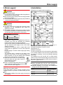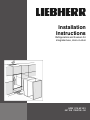
1
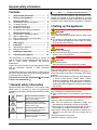
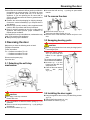
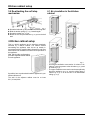
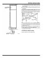
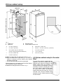
Installation
Instructions
Refrigerators and freezers for
integrated use, door-on-door
HRB 1110 HF 851
041108 7084158 - 00
General safety information
Contents
Note
1
General safety information...........................
2
2
Setting up the appliance...............................
2
3
3.1
3.2
3.3
3.4
3.5
Reversing the door........................................
Detaching the soft stop mechanism.................
To remove the door..........................................
Swapping bearing parts...................................
Installing the door again...................................
Re-attaching the soft stop mechanism.............
3
3
3
3
3
4
4
4.1
4.2
4.3
4.4
Kitchen cabinet setup...................................
Air circulation in the kitchen cabinet.................
Kitchen cabinet setup.......................................
Kitchen cabinet setup for the water filter...........
Cabinet door setup...........................................
4
4
5
6
7
5
Water supply..................................................
9
6
6.1
6.2
Installation...................................................... 9
Assembling the appliance................................ 10
Fitting the unit doors......................................... 11
7
Installing the water filter............................... 13
8
Connecting the appliance............................. 14
The manufacturer is constantly working to improve all
models. Therefore please understand that we reserve the
right to make design, equipment and technical
modifications.
To get to know all the benefits of your new appliance, please
read the information contained in these instructions
carefully.
The instructions apply to several models, so there may be
differences. Sections which only apply to certain appliances
are indicated with an asterisk (*).
Instructions for action are marked with a , the results
of action are marked with a .
1 General safety information
Read and follow these instructions. They contain safety
advice which is important for safe and problem-free
installation and operation. Always read and follow the safety
advice.
DANGER
2
indicates a hazardous situation,
which if not avoided, will result in
death or serious injury.
WARNING
indicates a hazardous situation,
which if not avoided, could result in
death or serious injury.
CAUTION
indicates a hazardous situation,
which if not avoided, will result in
minor or moderate injury.
NOTICE
indicates a hazardous situation,
which if not avoided, could result in
damage to property.
indicates useful advice and tips.
It is important that the guidelines and instructions in this
manual are followed so that the appliance is correctly
installed and operates properly. Read and understand all
information in this manual before the appliance is installed.
2 Setting up the appliance
WARNING
Risk of fire due to moisture!
If live parts or the power cord get wet, this can cause a short
circuit.
u The appliance is designed for use in enclosed spaces.
Do not operate the appliance in open space or in damp
areas or where there is spray.
WARNING
Danger of fire and damage!
u Do not place devices that give off heat, e.g. microwaves,
toasters, etc. on the appliance.
CAUTION
Risk of personal injury!
u Have two people move this appliance into place.
NOTICE
Risk of damage caused by condensation
Installing the appliance next to any other refrigerator or
freezer can cause condensation or damage to the Liebherr
appliance.
u Do not install this appliance next to any other refrigerator
or freezer except another Liebherr model. Liebherr
models are designed to allow side-by-side installation.
They are equipped with a heating system to eliminate
condensation when refrigerators or freezers are installed
side-by-side.
NOTICE
Risk of damage for the finished floor surface!
u Protect the finished floor surface before you uncrate the
unit.
Verify that:
q the floor under the appliance is flat and level.
q the floor can support the appliance's weight plus
approximately 1200 pounds (544 kg) of food weight.
q the appliance is not placed in direct sunlight or near the
stove, range top, radiators and similar heat sources.
q the kitchen cabinet that the appliance is installed in is
shimmed to the floor level if the floor heights are not
equal.
q cutout dimensions are accurate.
q electrical outlet is in correct location.
Reversing the door
q the air flow is not restricted. Air flow must be provided for
the appliance to operate properly. The factory air vents
provide 31 square inches (200 cm2) of air flow per
appliance. If you are replacing the air vents with an
overlay, the air flow must be the same or greater than the
factory air vents.
u Examine the unit and packaging for shipping damage.
Contact the carrier immediately if you suspect there is
any damage.
u Note the type (model, number), index, appliance/serial
number, date of purchase and where purchased .
u Remove anything attached to the rear or side walls of
appliance that would prevent proper installation or
impede proper ventilation.
If the appliance is set up in humid areas, condensation may
build on the outside of the appliance.
u Always ensure proper ventilation.
3 Reversing the door
Make sure you have the following tools on hand:
q Phillips screwdriver
q Slot screwdriver
q • Cordless screwdriver Torx 15
• Cordless screwdriver Torx 20
• Cordless screwdriver Torx 25
Disconnect the power plug.
Open the door.
u Unscrew the ball stud Fig. 1 (3) using an open-ended
wrench.
3.2 To remove the door
Fig. 2
u Remove the covers Fig. 2 (4).
u Just loosen the fixing screws Fig. 2 (5).
u Remove door: Push outwards, unhook and put to one
side.
3.3 Swapping bearing parts
CAUTION
Hinges are spring-loaded and can cause pinching injuries!
u Leave hinges open.
u Swap the fixing screws
Fig. 2 (5) on the top and
bottom to the opposite
side.
The screws are self-tapping.
Use a cordless screwdriver:
u Unscrew Fig. 3 (9) the
hinges from the door and
swap them over.
u Close off the now unused
holes
with
plugs
Fig. 3 (10).
3.1 Detaching the soft stop
mechanism
Fig. 3
Fig. 1
CAUTION
Risk of injury if soft stop contracts!
u Detach with care.
u Use a screwdriver to slide the tension spring Fig. 1 (11)
outwards.
u Remove the soft stop mechanism Fig. 1 (2) by pulling it
downwards.
u Unscrew the retainer Fig. 1 (1).
3.4 Installing the door again
u Hang the appliance door on the pre-fitted fixing screws
Fig. 2 (5).
u Tighten the fixing screws Fig. 2 (5).
u Re-attach the covers Fig. 2 (4).
3
Kitchen cabinet setup
3.5 Re-attaching the soft stop
mechanism
4.1 Air circulation in the kitchen
cabinet
Fig. 4
u Screw the ball stud Fig. 4 (3) into the new fastening hole.
u Slide the tension spring Fig. 1 (11) inwards again.
u Screw the retainer Fig. 4 (1) on.
u Attach the soft stop mechanism Fig. 4 (2) onto the ball
stud.
4 Kitchen cabinet setup
This is a built-in appliance and is therefore completely
enclosed by a kitchen cabinet. The kitchen cabinet
surrounding the appliance must be set up exactly in
accordance with the specified fitting dimensions and must
allow sufficient air circulation to ensure correct operation of
the appliance.
With side-by-side configurations,
provide a separate kitchen cabinet
for each appliance.
Fig. 5
If possible, have a professional install the appliance in your
kitchen cabinet unit.
The wall of the adjacent cabinet must be at least
5/8 '' (16 mm) thick.
4
- An effective ventilation cross-section of at least 31 in2
(200 cm2) must be present at the air intake Fig. 5 (1) and
air outlet Fig. 5 (2).
- The upper ventilation cross-section can be set up directly
above the appliance Fig. 5 (2), near the ceiling above a
cabinet Fig. 5 (3), or as an air vent in an intermediate
ceiling Fig. 5 (4).
Kitchen cabinet setup
- An unobstructed air way with a depth of at least
1 1/2 in. (38 mm) must be ensured at the back of the
kitchen cabinet.
u The air-circulation clearances indicated above must be
maintained.
The ventilation from below through the cabinet floor can be
provided with the supplied ventilation grille Fig. 7 (3) or a
ventilation opening of with a cross-sectional area of at least
31 in2 (200 cm2). If you are using the supplied ventilation
grille Fig. 7 (3), proceed as follows:
Fig. 7
u In the cabinet floor, cut a ventilation opening
17 23/32 in. (450 mm) wide and 2 7/32 in. (56 mm) high.
u Insert the ventilation grille Fig. 7 (3) into the cutout in the
cabinet floor Fig. 7 (1).
u Slide the snap connectors Fig. 7 (2) into the grille from
behind until the hooks touch the cabinet floor.
u Fit the cabinet floor (with the ventilation grille snapped
into place) into the cabinet.
4.2 Kitchen cabinet setup
Install the appliance in fixed cabinets only.
Fig. 6
5
Kitchen cabinet setup
Fig. 7
1
2
Power cord
Spirit level
3
4
Electrical socket
Pull-in cable for power cord
A
21-7/32 in. (539 mm)
B
69-21/32 in. (1769.5 mm)
C
21-15/16 in. (557 mm)
D
69-3/4 in. - 70-3/8 in. (1772 mm) - (1788 mm)
E
24 in. (609.6 mm) (U.S. dimension)
F
21-21/32 in. (550 mm)
23-5/8 in. (600 mm) (European dimension)
G
1-1/2 in. (38 mm)
J
66-1/2 in. (1689.9 mm)
K
max. 3/4 in. (19 mm)
L
9-21/32 in. (245 mm)
u Build the cabinet with the dimensions shown in Fig. 7.
u Align the cabinet with a spirit level Fig. 7 (2) and a try
square. If necessary, level the cabinet up by placing
something underneath.
w The floor and side walls must be at right angles.
Maintain clearance L to the wall to ensure that the drawers
can be pulled out without obstruction.
u Maintain the fitting dimensions shown in Fig. 7.
6
4.3 Kitchen cabinet setup for the water
filter*
The water filter module is supplied with the
appliance. It should be installed near the
appliance in the cabinet, for example, in the
adapter cabinet above the appliance. To
connect the filter to the appliance, it may be
necessary to make an opening (C) in the
floor of the adapter cabinet through which
the hoses will be routed. The maximum
length of the water hose is 98-7/16 '' (2.5 m).
The filter cover must be installed during
assembly to leave sufficient space around
the filter module.
Kitchen cabinet setup
Fig. 8
(A) 13/16in (20mm)
(C) 1-3/16in. x 3/8in.
( 30mm x 10mm )
(B) 3-15/16in (100mm)
(D) min. 4in (100mm)
u Maintain the dimensions shown in Fig. 8 so that the filter
can be replaced and the cover can be removed.
u The tape on the water filter is not needed and can be cut
off.
The cabinet must have a door.
This door is generally constructed as follows:
- The door must be at least 5/8 in. (16 mm) and at most
3/4 in. (19 mm) thick so that the connecting rails can be
fixed on it.
- There must be a gap Fig. 9 (1) at least 1/8 in. (3 mm) wide
between the door and the cabinet door above it (if
present).
- The width of the cabinet doors depends on the kitchen
style and size of the gaps between the door panels of the
cabinetry. Generally, a 1/8 in. (3 mm) vertical gap
between the cabinet doors is recommended.
- The upper edge of the door Fig. 9 (2) should be level with
the door of the adjacent cabinet (or cabinets), if other
cabinets are present.
- Align the door before installing the appliance. Once you
have installed the appliance, you can no longer correct
the door position.
u Check the fitting dimensions according to the
specifications in Fig. 7.
4.4 Cabinet door setup
Fig. 9
7
Kitchen cabinet setup
Fig. 9
1 Cabinet door
2 Appliance door
The height of the cabinet door is calculated as follows:
u Total cabinet height (i. e., 69-21/32 in. (1769.5 mm)) plus
the thickness of the cover plate and floor plate Fig. 9 (a)
(usually 3/4 in. (19 mm))/ 69-21/32 in. + 3/4 in. + 3/4 in.
= 71-5/32 in. ( 1769.5 mm + 19 mm + 19 mm =
1807.5 mm )
8
Water supply
5 Water supply*
6 Installation
All fasteners are supplied with the appliance.
WARNING
Electrical Shock Hazard!
u Do not make the water connection while the appliance is
connected to an electrical outlet.
u Disconnect the water supply before connecting the water
lines for the IceMaker.
u The connection to the water supply may only be made by
a trained and licensed plumber.
WARNING
Poisoning Hazard!
u The water quality must comply with the drinking water
regulations for the geographical area where the
appliance is located.
u The IceMaker is designed exclusively to make ice cubes
in quantities needed by a household and must only be
operated with water appropriate for this purpose.
Water pressure:
bar
psi
MPa
1.5 to 6 21.76 to 87.02 0,15 to 0,6
- Water must be supplied to the appliance by means of a
cold-water pipe that can withstand the operating
pressure and conforms to hygiene regulations.
- A shut-off valve must be provided between the hose line
and the domestic water supply to turn off the water
supply, if necessary.
- All devices and fixtures used to supply water must
comply with the regulations in force in the respective
country.
- Do not damage or bend the water supply pipe during
installation.
- The solenoid valve is located on the back of the
appliance at the bottom. It has a European Metric R¾
male connection. Do not use Garden Hose Threaded
fittings on the solenoid valve - they will leak.
u Open the shut-off valve of the water supply
pipe and check the entire water system to
ensure there are no leaks.
Before initial operation:
u Have a competent fitter bleed all air from the
water supply pipe. IceMaker will not function if
there is air in the water supply line.
NOTICE
Malfunction of the water intake!
If the water intake is shut off during operation but the
IceMaker remains in operation, the water intake pipe may
ice up.
u Switch off the IceMaker if the water supply is interrupted
(e.g. holiday).
Fig. 10
Make sure you have the following tools on hand:
q Cordless screwdriver Torx® 15, 20, 25
q Hex wrench 13
q Phillips screwdriver
The floor and side walls of the unit must be at right angles
to one another. Make the unit level using a spirit level and
set square. If necessary, level up by placing something
underneath.
The appliance can also be built into a normal kitchen
cabinet. In this case detach the fittings of the unit door and
the recess. They are no longer needed as the unit door is
fitted to the appliance door.
Note
u Before assembling the unit door, make sure that the
permitted weight for the unit doors is not exceeded.
u Otherwise damage to the hinges and malfunctions
arising from this cannot be ruled out.
Model
Maximum weight of
unit door
IKB 3650
39.68 lbs (18 kg)
IGN 2566
44.09 lbs (20 kg)
9
Installation
u Connect the supplied extension hoses to the appliance
hoses: Slide the appliance hoses into the connectors as
far as they will go (approx. 21/32 '' (17 mm)).*
u Position the hoses using a piece of
string so that they can be
connected to the water filter later
(see 4.3) .*
*
Appliances with a plumbed-in connection for the
IceMaker:
u Connect the IceMaker .*
All appliances:
u Push the appliance 3/4 of the way into the recess.
u Remove covers Fig. 11 (4,6,7).
u Screw Fig. 15 (11) the
equalizer trim Fig. 15 (24)
onto the top of the
appliance through the
oblong holes.
6.1 Assembling the appliance
u Fasten
a
mounting
Fig. 11
Unit depth less than 21 3/4 in. (553 mm) Detach the
spacers from the rear of the appliance so that you can slide
the appliance completely into the recess. Removing the
spacers may cause the appliance to use more energy, as
this reduces the ventilation cross-section.
pair
of
brackets
Fig. 16 (12) into the prebored holes in the
appliance door with a
hex
head
screw
Fig. 16 (13).
For large or divided unit doors:
u Fit a 2nd pair of mounting brackets
Fig. 28 (12).
u Use the holes pre-drilled in handle area of
the appliance door for this purpose.
Fig. 15
Fig. 16
Fig. 12
u Undo the screw Fig. 12 (50) and detach the spacer
Fig. 12 (51).
All appliances:
u Remove the power cord from the back of the
appliance. Also remove the cable holder, otherwise
there will be vibration noise!
u Position the power cord using
a piece of string so that the
appliance can easily be
connected to the electricity
supply after it has been built-in.
Fig. 13
For appliances with a water filter:*
u Remove the connector
Fig. 14 (52) from the hose
ends: Press the dark gray
clip Fig. 14 (53) into the
connector while at the same
time pulling out the hose
Fig. 14 (54).*
10
Fig. 14 *
With 5/8 '' (16 mm) thick
unit walls:
u Clip spacer Fig. 17 (14) and
spacer Fig. 11 (15) onto the
hinge.
u Place
the
covers
Fig. 18 (16) top and bottom
onto
the
mounting
brackets Fig. 18 (17).
u Fasten the mounting
brackets Fig. 18 (17) on top
with screws Fig. 18 (19) and
on the bottom with
Screws Fig. 11 (19) such
that the bracket still has a
slight bit of play to the left
and right.
Fig. 17
Fig. 18
Installation
u Remove the protective film from the
trim Fig. 19 (20).
u Place the trim Fig. 19 (20) on the flange of
the cover Fig. 18 (16), on the handle side
and flush with the front, and adhesively
affix it to the side wall of the appliance.
u If necessary, shorten the trim
Fig. 19
Fig. 19 (20) at the bottom: The trim
Fig. 19 (20) must end 1/8 '' (3 mm) above
the upper edge of the bottom mounting
bracket Fig. 11 (17).
Insert and align appliance:
u Slide the appliance in until it contacts Fig. 18 (16) the
covers Fig. 18 on the side wall of the unit.
With 5/8 '' (16 mm) thick unit
walls:
u Slide the appliance into the
recess until it touches the
spacers on the side wall of the
Fig. 20
unit.
With 3/4 '' (19 mm) thick
unit walls:
u Align the front edges of the
hinges flush with the side wall
of the unit.
Fig. 21
Units (5/8 '' (16 mm) and 3/4 '' (19 mm)) with door
stop components (knobs, sealing lips, etc.):
u Note the additional space needed (for depth of door stop
components): Allow the hinges and covers Fig. 18 (16) to
protrude by the additional distance.
All appliances:
u Adjust the adjustable feet with the supplied open-ended
wrench Fig. 11 (21) to align the appliance vertically.
w The appliance is now positioned correctly depthwise.
The distance between the front edge of the unit side wall
and the appliance itself is 42 mm all around. (Note the
additional space needed for door stop components such
as knobs and sealing lips.)
Note
Malfunction due to incorrect assembly!
If the spacing is not observed, the appliance door may not
seal completely. This can cause icing up, the formation of
condensate, and malfunctions.
u A continuous space of 1-21/32 '' (42 mm) must be
maintained. (Note the additional space needed for door
stop components such as knobs and sealing lips.)
u Screw long chipboard screws
Fig. 22 (22) at the top and at the
bottom through the hinge plates.
Take care that screws will not
protrude from an exposed end
cabinet wall.
Fig. 22
On the top handle side:
u Loosen the screws
Fig. 23 (19) slightly.
u Secure the top mounting
bracket Fig. 23 (17) with a
ø4x19 chipboard screw
Fig. 23 (25) to the unit
wall.
u Break off the protruding
Fig. 23
end of the cover
Fig. 23 (16).
u Tighten the screws Fig. 23 (19).
u Place cover Fig. 23 (16) in position.
On the bottom handle side:
u Loosen
the
screws
Fig. 24 (19) slightly.
u Secure
the
bottom
mounting
bracket
Fig. 24 (17) with a ø4x19
chipboard
screw
Fig. 24 (25) to the unit wall.
u Break off the protruding
end
of
the
cover
Fig. 24 (16).
u Tighten
the
screws
Fig. 24 (19).
Fig. 24
u Place
the
cover
Fig. 24 (23) onto the
bottom mounting bracket
Fig. 24 (17).
u Slide the equalizer trim Fig. 15 (11) toward the handle side
as far as it will go.
u Close the appliance door.
6.2 Fitting the unit doors
To secure the appliance in the recess:
Fig. 25
11
Installation
u Check 5/16 '' (8 mm) presetting (distance between
appliance door and lower edge of crosspiece).
u Raise the fitting aids Fig. 25 (30) to the unit door height.
Bottom stop angle ▲of fitting aid = upper edge of the unit
door to be fitted.
u Unscrew the crosspiece Fig. 26 (31) by undoing the
locknuts Fig. 25 (32).
u Hang the crosspiece
Fig. 26 (31) on the
inside of the unit door
using the fitting aids
Fig. 26 (30).
With
a
23-5/8 '' (600 mm)
wide cabinet:
u To
center
the
crosspiece
Fig. 26 (31): Mark a
Fig. 26
short center line on
the unit door and put
the tip of the arrow on
the crosspiece on it.
w Distances to the outer edges are the same to the right
and to the left.
With a 24 '' (609.6 mm) wide cabinet:
u To align the crosspiece Fig. 26 (31): Mark a short center
line on the unit door and put the tip of the arrow on the
crosspiece on it. Then slide the crosspiece
Fig. 26 (31)3/16 in. (5.5 mm) toward the hinge side.
For chipboard doors:
u Secure the crosspiece Fig. 26 (31) with at least 6 screws
Fig. 26 (34).
For frame and panel doors:
u Secure the crosspiece Fig. 26 (31) with 4 screws
Fig. 26 (34) at the edge.
u Lift up the fitting aids Fig. 26 (30), turn around and insert
into the adjacent openings.
Fig. 27
u Attach the unit door on the adjusting bolts Fig. 27 (33) and
loosely screw the locknuts Fig. 27 (32) onto the adjusting
bolts.
u Close the door.
u Check the gap between the door and the surrounding unit
doors.
u To laterally align the unit door: Move the unit door in the
X direction.
u To align the unit door in the Y direction (height) and in
lateral inclination: Adjust the adjusting bolts Fig. 27 (33)
with a screwdriver.
w The unit door is flush and in alignment with the
surrounding unit fronts.
u Tighten the locknuts Fig. 27 (32).
12
Fig. 28
Ensure that both metal edges are flush, symbol //:
u Drill pilot holes in the door of the unit taking care not to
go all the way through the panel (you could make a
preliminary hole with a bradawl).
u Screw the appliance door to the unit door with screws
Fig. 28 (34) through the mounting brackets Fig. 28 (12).
Fig. 29
u To align the unit door in depth Z: Undo top screws
Fig. 29 (35), bottom hex head screws Fig. 29 (13), then
move the door.
u Do not allow the knobs and sealing lips
to contact the door - important for
functioning!
u Set an air gap of 3/32 '' (2 mm) between
the door of the unit and the body of the
unit.
Fig. 30
u Check the fit of the door and re-adjust, if necessary.
u Tighten all screws.
u Tighten the locknuts Fig. 30 (32) with the ring wrench
Fig. 30 (38), while counter-holding the adjusting bolts
Fig. 30 (33) with a screwdriver.
Installing the water filter
u Position the upper cover
Fig. 31 (39) and snap into
place.
u Place the lateral cover
Fig. 31 (40) in position, slide
to the limit and then press
until it snaps audibly into
place.
u Attach covers Fig. 31 (41) to
the side and then draw
them forward with a
screwdriver, so that they
snap properly into place.
Fig. 31
With a 24 '' (609.6 mm) wide recess:
u Position the covers Fig. 11 (6,7,42) and snap them into
place.
With a 23-5/8 '' (600 mm) wide recess:
u Position the covers Fig. 11 (4,6,7) and snap them into
place.
Check the following points to make sure the appliance is
installed correctly. Otherwise, icing up, the formation of
condensate, and malfunctions can occur.
w The door must close properly.
w The unit door must not touch the body of the unit.
w The seal on the upper corner on the handle side must be
fitted securely. To verify this, darken the room, place a
flashlight in top part of the appliance, and close the door.
If you see light shining out, check the assembly.
7 Installing the water filter*
The water filter guarantees optimal water quality and should
be installed the first time you use the appliance.
Alternatively, the appliance can also be operated without
the water filter.
Flow rate
0.5 gpm (1.89 lpm)
Water connection
Public or private source
Water pressure
40 psi - 90 psi ( 2.8 bar - 6.2 bar/ 0.28 MPa
- 0.62 MPa )
Water temperature 33 °F - 100 °F ( 0.6 °C - 37 °C )
Capacity
500 gal. (1893 l)
WARNING
Consuming contaminants can be harmful to your health!
u If there is a chance the water may contain harmful
bacteria or if the water quality is unknown, do not use this
system without appropriate disinfection measures
upstream or downstream of the system.
NOTICE
Leakage water may damage the system!
u Do not install this system on hot water lines. The
maximum operating temperature of the water in this
system is 100 °F (37.7 °C).
u This system MUST be installed and used in compliance
with federal and local installation regulations.
u Do not install under water hammer conditions. A water
hammer arrestor must be used to prevent water
hammering. If you are unsure how to check these
conditions, consult a professional installer.
u Do not install with a water pressure greater than 90 psi
(6.2 bar). If your water pressure exceeds 80 psi, install a
pressure limiting valve. If you are unsure how to check
the water pressure, consult a professional installer.
u Protect against frost; if temperatures below 33 °F
(0.6 °C) are expected, remove the filter.
u When used as indicated, the disposable filter cartridges
must be replaced every 6 months or whenever you notice
a considerable decrease in the flow rate.
Make sure that the following conditions are
fulfilled:
q The hoses have been positioned such
that they can now be connected to the
filter.
q The installation position has been
selected according to the instructions
(see 4.3) .
q The connectors have been removed from
the hose ends.
u Hoses have been shortened, if necessary
(cut at 90° angle to the direction of the
hose).
When doing so, make sure the hoses do not become kinked
and the cross-section of the hose remains round.
u On the thin hose, measure the
insertion depth (E) of 21/32 '' (17 mm)
and mark it.
u On the thick hose, measure the
insertion depth (E) of 25/32 '' (20 mm)
and mark it.
u Insert
the
hoses
Fig. 32 (1)all the way into
the water filter module
(i.e., up the the mark you
made), past the point of
resistance.
Fig. 32
13
Connecting the appliance
Note
u In case of disassembly: Press back the dark grey ring on
the plug-in elbow and pull out the hose at the same time.
8 Connecting the appliance
u Pull the tray Fig. 33 (4)
out until it catches.
u Secure the module
with
4
screws
Fig. 33 (5) through the
recesses in the front
and directly through
the module in the
back.
u Place the tray cover
Fig. 35 (3) in position.
WARNING
Electrical shock hazard!
u Start-up should only take place once the appliance has
been installed according to these instructions.
u Electrically ground appliance.
u Do not ground to a gas pipe.
u Check with a qualified electrician if you are not sure the
appliance is properly grounded.
u Do not have a fuse in the neutral or grounding circuit.
u Do not use an extension cord, power bar or a multiple
socket adapter.
u Do not use a power cord that is frayed or damaged.
Fig. 33
Fig. 34
Fig. 35
u Insert the water filter Fig. 35 (6) and turn it approximately
100° to the right until it locks into position.
u Place the cover Fig. 35 (2) on the filter.
u Slide the tray in.
u Write the date of the next filter replacement on the
supplied adhesive label and affix it to the module.
u Make sure the filter is leak-tight and no water is coming
out.
Note
New water filters may contain particulate matter and must
be rinsed through before use.
u To achieve this, do not consume or use the ice cubes that
are produced within 72 hours after the filter is replaced.
w The water filter is now ready for use.
14
WARNING
Electrical shock hazard!
This appliance is equipped with a three-prong (grounding)
polarized plug for your protection against possible shock
hazards. Electrical Grounding Required.
u Do not remove the round grounding prong from the plug.
u Do not use a two-prong grounding adapter.
- Wait 30 minutes up to 1 hour after installation before you
plug in the appliance. This allows the refrigerant and
system lubrication to reach equilibrium.
- Make sure incoming voltage is the same as the appliance
rating. A 110-120 Volt, 60 Hz, 15 Amp electrical supply
(20 Amp for side-by-side installations) circuit that is
controlled by a circuit breaker or fuse is required.
- We recommend using a dedicated circuit for this
appliance to prevent electrical overload.
- Follow all Federal, State and local electrical, fire and
building codes and ordinances when installing the
receptacle and / or the appliance.
- In some communities, a wall switch is required to turn
power to the appliance ON and OFF.
- To reduce the risk of fire, electric shock, or personal
injury, installation work and electrical wiring must be
done by a qualified electrician in accordance with all
applicable codes and standards, including fire-rated
construction.
- You are advised to clean the appliance before switching
it on the first time .
- The top of the electric outlet must be located within
82-5/8 in. (2100 mm) from the top of the base in the
cabinet.