1
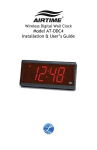
Wireless Digital Wall Clock
Model ATDDC4
Installation & User’s Guide
THIS EQUIPMENT COMPLIES WITH FCC REQUIREMENTS
PURSUANT SUBPART J OF PART-15
Other AirTime Products
This device complies with Part 15 of the FCC Rules. Operation is subject to the following two
conditions: (1) this device may not cause harmful interference, and (2) this device must accept any
interference received, including interference that may cause undesired operation.
WARNING: Changes or modifications to this product not expressly approved by the party responsible
for compliance could void the user’s authority to operate this equipment.
NOTE: This equipment has been tested and found to comply with the limits for a digital device,
pursuant to Part 15 of the FCC Rules. These limits are designed to provide reasonable protection
against harmful interference in a residential installation. This equipment generates, uses, and can
radiate radio frequency energy and, if not installed and used in accordance with the instructions, may
cause harmful interference to radio communications. However, there is no guarantee that
interference will not occur in a particular installation. If this equipment does cause harmful
interference to radio or television reception, which can be determined by turning the equipment off
and on, the user is encouraged to try to correct the interference by one or more of the following
measures:
- Reorient or relocate the receiving antenna.
- Increase the separation between the equipment and receiver.
- Connect the equipment into an outlet on a circuit different from that to which the receiver is
connected.
- Consult the dealer or an experienced radio TV technician for help.
ATX
Mini Transceiver capable of
receiving the WWVB signal and
transmitting exact time in smaller
facilities
AT12RPS
Solar Powered 12” Analog
Wireless Wall Clock
AT-ANTOD
Outdoor Antenna for maximum
coverage with the ATX6 or the AT20WT
AT-MSX
AirTime receiver that accepts the AirTime signals from
an ATX, ATX6 or AT20WT and
corrects Lathem RS485
devices or Intercom systems
via a 12:00AM dry contact
closure
This equipment complies with FCC radiation exposure limits set forth for an uncontrolled
environment. This equipment should be installed and operated with minimum distance 20cm between
the radiator and your body. This Transceiver must not be co-located or operating in conjunction with
any other antenna or Transceiver.
Disclaimer
The information within this document has been carefully checked and is believed to
be entirely reliable. However, no responsibility is assumed for inaccuracies. Lathem
Time Corp. reserves the right to make changes to any products herein to improve
reliability, function, or design.
Trademark
AirTime, Lathem and the Lathem logo are registered trademarks of Lathem Time
Corporation. Other product names mentioned in this manual may be trademarks of their
respective companies and are hereby acknowledged.
WARNING: Changes or modifications to this product not expressly approved by the party
responsible for compliance could void the user’s authority to operate this equipment.
Copyright © 2009 Lathem Time Corporation. All rights reserved.
Lathem Inc
200 Selig Drive SW
Atlanta, GA 30336
www.lathem.com
Contact your distributer or visit www.lathem.com for more information
ATDDC4 Series Installation & User’s Guide
ATDDC4 Series Installation & User’s Guide
One Year Limited Warranty
Lathem warrants the hardware products described in this guide against
defects in material and workmanship for a period of one year from date
of original purchase from Lathem or from an authorized Lathem
reseller. The conditions of this warranty and the extent of the
responsibility of Lathem Time Corporation (“Lathem”) under this
warranty are listed below.
1. This warranty will become void when service performed by anyone other than an
2.
3.
4.
5.
6.
7.
8.
9.
approved Lathem warranty service dealer results in damage to the product.
This warranty does not apply to any product which has been subject to abuse,
neglect, or accident, or which has had the serial number altered or removed, or
which has been connected, installed, adjusted, or repaired other than in accordance
with instructions furnished by Lathem.
This warranty does not cover dealer labor cost for removing and reinstalling the
machine for repair, or any expendable parts that are readily replaced due to normal
use.
The sole responsibility of Lathem under this warranty shall be limited to repair of
this product, or replacement thereof, at the sole discretion of Lathem.
If it becomes necessary to send the product or any defective part to Lathem or any
authorized service dealer, the product must be shipped in its original carton or
equivalent, fully insured with shipping charges prepaid. Lathem will not assume any
responsibility for any loss or damage incurred in shipping.
WARRANTY DISCLAIMER AND LIMITATION OF LIABILITY: Except only the limited
express warranty set forth above, the products are sold with no expressed or
implied warranties of any kind, and the implied warranties of merchantability and
fitness for a particular purpose are hereby expressly disclaimed. No warranties are
given with respect to products purchased other than from Lathem or an authorized
Lathem reseller and any such products are purchased "as is, with all faults." In no
event will Lathem be liable for any direct, indirect, special, incidental or
consequential damages arising out of or in connection with the delivery, use or
inability to use, or performance of this product. In the event any limited remedy
given herein shall be deemed to have failed of its essential purpose, Lathem's
maximum liability shall be to refund the purchase price upon return of the product.
Proof of date of purchase from Lathem or an authorized Lathem reseller is required
for warranty service on this product.
This Warranty grants specific legal rights. Additional legal rights, which may vary by
locale, may also apply.
Should any difficulties arise with the performance of this product during warranty,
or with any Lathem authorized service centers, contact Lathem Time at the
address below:
Lathem Inc
200 Selig Drive SW
Atlanta, GA 30336
www.lathem.com
Form USG0084
Page 12
Introduction
The AirTime ATDDC4 Wireless Digital Display Wall Clock is designed
with a 4-inch red LED display that can be viewed from distances over
100 feet. The optional 6 digit version provides 2 additional 2-inch
digits. The bright red display shows the hour and minutes or as an
option the hour, minutes and seconds; can be configured for a 12 or 24
Hour format; and keep time synchronized to a Lathem ATX series
transceiver’s wireless correction signal. The ATDDC4 series Wall Clocks
can be mounted directly to a wall, to a single gang outlet box or, with
optional mounting kits, as double-faced units from the wall or ceiling.
Clock Operation
When the ATDDC4 series Wall Clock is connected to 120vAC (24vAC
optional) power, it displays the firmware version for 3 seconds and
then changes to 12:00 AM. A flashing LED in the lower right indicates
that it is listening to acquire its initial synchronization signal. When a
signal is received the LED will extinguish and the internal clock will be
set. Note: It may take up to several minutes for the clock to initially
synchronize. After initial reception, the LED will only flash when future
sync signals are received. The clock will continuously listen and correct
itself as needed.
Front Panel
Front Panel with optional 6 digit display
ATDDC4 Series Installation & User’s Guide
Specifications
Clock Installation
Tools required for mounting the clock:
•
•
•
•
•
ATDDC4 Series Installation & User’s Guide
Drill with a 5/16" bit
Hammer
Phillips head screwdriver
Wall anchors
Pencil
Separate the electronics from the enclosure and to set the Time
Display Format (12hr / 24hr). To do this, remove the plastic end caps,
each secured with two Phillips-head screws. Slide the front lens out of
the front track, then slide the circuit board and display out of the
second track in the enclosure. Carefully place each down on a smooth,
clean surface.
Time Formats
The ATDDC4 Series Wall Clocks can display either 12 Hour or 24 Hour
format. When in 12 Hour format, a red LED in the upper left corner of
the display indicates PM hours. When in 24 Hour format, the hours are
displays in Military style.
Dimensions
6 3/4" H X 15 1/2" W X 3 1/8" D
17.1 cm H X 39 cm W X 7.9 cm D
Weight
9 lbs. (4.086 kg)
Display
4-Inch 7-Segment LED for Hours and Minutes
2-inch 7-Segment LED for Seconds (optional)
Housing
Extruded aluminum main case with black textured
paint, molded plastic end caps with black texture.
Line Power
120VAC, 80mA typical
24vAC, 400mA typical (optional)
FCC
Conforms to FCC Part 15
Environment
32o to 140 o F (0 o to 60 o C)
95% Relative Humidity (non-condensing)
Mounting
Wall (surface)
Single Gang Box (surface)
Double Face (wall or ceiling) (optional)
12 Hour Format
Ordering Options
AM
PM
24 Hour Format
AM
ATDDC4
Optional
Optional
VSE0050
SAM0625
SAM0626
VIS1551-L
VIS1551-R
Wireless Digital Clock, 4 Digits (HH:MM), 120vAC
6 Digit display (HH:MM:SS)
24vAC Input
120vAC Power Cord Kit
Double Wall-Mounting Kit
Double Ceiling-Mounting Kit
Pre-Drilled End Panel (Left)
Pre-Drilled End Panel (Right)
PM
Page 2
Page 11
ATDDC4 Series Installation & User’s Guide
ATDDC4 Series Installation & User’s Guide
To set the display format, use the jumper (J1) located on the back of
the circuit board which can be accessed by removing the right side end
cap and sliding the circuit board out slightly.
Back Side of Circuit Board
Jumper J1
On = 12 Hour display
Off = 24 Hour display
Mounting the Enclosure
5. Slide the circuit board assemblies in partially and secure the
required wiring.
6. Slide the circuit board assemblies in fully, then slide the front
lenses into place. Note: the inside of the lens has a paper
backing which should not be removed. The end with wider
paper should go to the right. Replace the end caps and secure
each with two Phillips head screws.
Page 10
The ATDDC4 Series Wall Clock can be mounted directly to a wall, to a
single gang outlet box or, with optional mounting kits, as double-faced
units from the wall or ceiling.
Remember that 120VAC power is needed when selecting the clock’s
mounting location (24vAC Power optional).
Select a method from among the following options:
Page 3
ATDDC4 Series Installation & User’s Guide
Mounting to a Wall
After deciding where to mount the clock, make two marks 12" apart
and horizontal. Note: If mounting near a ceiling, make sure the holes
are at least 2 1/4" away from the ceiling. Also, provide at least 16" of
side clearance on one side in order to remove the front panel.
Installation Steps
1. Drill a 5/16" hole at each mark
2. Insert a wall anchor and tap it flush to the wall with the hammer.
3. Insert a screw into each wall anchor leaving 1/4" exposed.
4. Line up the two keyholes on the back of the case and slip over the
two screws and tighten securely. ( The lower mounting holes can
be marked at this point, the case removed, holes drilled and wall
anchors installed if so desired)
Mounting to a Single Gang Box
ATDDC4 Series Installation & User’s Guide
Double Mount - Ceiling
Requires optional mounting kit (SAM0626)
Double-Mounting - Ceiling
Note: Make sure you have at least 16" of side clearance on one side in
order to remove the front panel assembly.
1. Place the two clock enclosures back to back and secure by inserting
a #10 screw through the four mounting holes using lock washers
and nuts supplied with the mounting kit.
2. Note: If the ATDDC4 clocks will be mounted too near a wall on one
side to secure the end caps, install the "wall side" end caps now.
3. Remove the center vent cap from the top of each ATDDC4 clock.
4. Line the two posts from the mounting plate up with the vent holes
of the ATDDC4 clocks. Insert the chase nipples through the vent
holes and secure to the mounting plate with a 15/16" wrench.
Two mounting holes are located in the center of the case 2 1/4" apart
for mounting to a single gang wall box. A 7/8" hole is located between
the mounting holes that will accommodate conduit, if desired.
Note: If mounting near a ceiling, make sure the holes are at least 21/4" away from the ceiling. Also, provide at least 16" of side clearance
on one side in order to remove the front panel.
Line the two holes in the case up to the single gang box and insert
proper screws for the single gang box and tighten securely.
Page 4
Page 9
ATDDC4 Series Installation & User’s Guide
ATDDC4 Series Installation & User’s Guide
Power Connection – Wall Mount
120vAC Electrical Supply can be brought into the ATDDC4 enclosure
from any of the six vent-hole positions, from the back, or from either
side. Conduit access is not available from the bottom.
Note: Optional plastic end-panels may be ordered (left VIS1551-L),
(right VIS1551-R) that have access holes pre-drilled for side access
.
Power Cord Installation
The optional AC Power Cord Kit (part# VSE0050) includes a 120vAC
Power Cord, metal fastener, 2 wire nuts and plastic strain relief that
can be installed through any of the available vent holes.
Strip away 1/2" of insulation from each wire of the power cord. Leave
eyelet on Ground Wire, if attached.
Remove the vent cap from the selected opening and insert the metal
fastener with the tabs toward the inside of the clock. Bend the tabs
down and away from the opening to secure it. Feed the cord through,
allowing sufficient length to attach the wires; including the ground.
Wrap the plastic strain relief around the cord close to the entry point,
squeeze it together and insert it into the metal fastener, to secure the
power cord to the enclosure.
5. Slide the circuit board assemblies in partially and secure the
required wiring.
6. Slide the circuit board assemblies in fully, then slide the front
lenses into place. Note: the inside of the lens has a paper backing
which should not be removed. The end with wider paper should
go to the right. Replace the end caps and secure each with two
Phillips head screws.
7. Discard or store the two original end caps that the modified end
caps replaced.
Power Cord Installation
Page 8
Page 5
ATDDC4 Series Installation & User’s Guide
ATDDC4 Series Installation & User’s Guide
Double Mount – Wall
Attaching Conduit
The ATDDC4 SERIES requires optional mounting kit (SAM0625)
The Electrical Supply can be brought into the ATDDC4 enclosure from
any of the top three vent-hole positions, from the back, or from either
side. Conduit access is not available from the bottom.
Note: Optional plastic end-panels may be ordered (left VIS1551-L),
(right VIS1551-R) that have access holes pre-drilled to allow side
access.
If Conduit access is through either of the optional plastic endpanels, Conduit should NOT be used to support the weight of the
Clock. The Clock must be properly secured to a wall.
Remove the vent cap from the selected mounting hole (if not accessing
through side panels). Attach the conduit with locking nut and extend
the wires into the enclosure.
Tools required for mounting the clock:
•
•
•
Flat blade screwdriver
Phillips head screwdriver
15/16" open end wrench
The double wall mount plate attaches to a double or single gang box
installed securely in the wall. Required wiring should be available
through the gang box at time of installation.
Installation Steps
1. Remove the two chase nipples from the mounting plate posts.
2. Secure the mounting plate securely to the gang box with the proper
screws. (not supplied)
Making the Connection
1. Slide the circuit board with display part-way back into the case.
Connect the two black wires from the circuit board to the powerwires from the power cord or conduit using wire nuts. Connect the
Ground Wires from the circuit board and from the power source
(usually green) to the green ground screw on the inside of he
enclosure.
2. Slide the circuit board fully into place, then slide the front lens
into place. Note: the inside of the lens has a paper backing
which should not be removed. The end with wider paper should
go to the right. Replace the end caps and secure with the two
Phillips head screws.
3. When the clock is energized, it will set itself, upon receiving the
AirTime radio signal.
Page 6
Note: The long dimension of the mounting plate must be perpendicular
to the ground to assure proper alignment of wall clocks.
See remaining Wall or Ceiling mount instructions below
Double-Mounting - Wall
1. Place the two clock enclosures back to back and secure by inserting
a #10 screw through the four mounting holes using lock washers
and nuts supplied with the mounting kit.
2. Attach the modified end cap to the clock’s end to be attached to
the wall mount plate using the original end cap screws.
3. Align the holes of end cap support plate with the holes in the
modified end cap and secure with 4 #6 Phillips head screws
(supplied).
4. Line the two posts from the mounting plate up with the two holes
of the modified end cap. Insert the chase nipples through the holes
of the modified end cap and secure to the mounting plate with a
15/16" wrench.
Page 7