1
Table of Contents
Operator’s Manual
RC45180 & RCM45180
Rotary Cutter
!
Read the Operator’s manual entirely. When you see this symbol, the subsequent instructions and warnings are serious - follow without exception. Your life and the lives of others
depend on it!
14115
Cover illustration may show optional equipment not supplied with standard unit.
© Copyright 2000 Printed 7/14/08
312-382M
Land Pride
Table of Contents
Table of Contents
Important Safety Information . . . . . . . . . . .1
Section 4 Troubleshooting . . . . . . . . . . .16
Safety Notations . . . . . . . . . . . . . . . . . . . . . . . . . . 1
Safety Rules . . . . . . . . . . . . . . . . . . . . . . . . . . . . . 1
General . . . . . . . . . . . . . . . . . . . . . . . . . . . . . . . 2
Transporting . . . . . . . . . . . . . . . . . . . . . . . . . . . 2
Tire Handling & Repair . . . . . . . . . . . . . . . . . . . 2
Safety Labels . . . . . . . . . . . . . . . . . . . . . . . . . . . . . 3
Section 5 Maintenance and Lubrication .17
Introduction . . . . . . . . . . . . . . . . . . . . . . . .7
Using This Manual . . . . . . . . . . . . . . . . . . . . . . . . . 7
Terminology: . . . . . . . . . . . . . . . . . . . . . . . . . . . 7
Definitions: . . . . . . . . . . . . . . . . . . . . . . . . . . . . 7
Owner Assistance . . . . . . . . . . . . . . . . . . . . . . . . . 7
Serial Number Plate . . . . . . . . . . . . . . . . . . . . . 7
Section 1 Assembly and Setup . . . . . . . . .8
Tractor Requirements . . . . . . . . . . . . . . . . . . . . . . 8
Before You Start . . . . . . . . . . . . . . . . . . . . . . . . . . 8
Dealer Cutter Assembly & Preparations . . . . . . . . 8
Left & Right Wing Axle Assembly . . . . . . . . . . . . . . 8
Hitch Assembly . . . . . . . . . . . . . . . . . . . . . . . . . . . 8
Slow Moving Vehicle
Bundle Assembly . . . . . . . . . . . . . . . . . . . . . . . . . . 9
Hydraulic Plumbing . . . . . . . . . . . . . . . . . . . . . . . . 9
Tractor Hookup . . . . . . . . . . . . . . . . . . . . . . . . . . 10
Section 2 Operating Instructions . . . . . .12
Operating Check List . . . . . . . . . . . . . . . . . . . . . . 12
Transporting . . . . . . . . . . . . . . . . . . . . . . . . . . . . 13
Parking . . . . . . . . . . . . . . . . . . . . . . . . . . . . . . . . 13
Maintenance . . . . . . . . . . . . . . . . . . . . . . . . . . . . 17
Service Cutting Blades . . . . . . . . . . . . . . . . . . . . . 17
Skid Shoes . . . . . . . . . . . . . . . . . . . . . . . . . . . . . . 17
Clutch Run-In . . . . . . . . . . . . . . . . . . . . . . . . . . . . 18
Storage . . . . . . . . . . . . . . . . . . . . . . . . . . . . . . . . 18
Lubrication . . . . . . . . . . . . . . . . . . . . . . . . . . . . . . 19
Axle Hub Bearing . . . . . . . . . . . . . . . . . . . . . . 19
Wing Hinges (6) . . . . . . . . . . . . . . . . . . . . . . . . 19
Ratchet Jack . . . . . . . . . . . . . . . . . . . . . . . . . . 19
Axle Rockshaft & Axle Link . . . . . . . . . . . . . . . 20
Main Hitch . . . . . . . . . . . . . . . . . . . . . . . . . . . . 20
Gearbox . . . . . . . . . . . . . . . . . . . . . . . . . . . . . 20
Divider Box . . . . . . . . . . . . . . . . . . . . . . . . . . . 20
Driveline Shaft . . . . . . . . . . . . . . . . . . . . . . . . . 21
Drive line Shafts . . . . . . . . . . . . . . . . . . . . . . . 21
PTO Constant Velocity Shaft . . . . . . . . . . . . . . 21
4-Plate Slip Clutch . . . . . . . . . . . . . . . . . . . . . . . . 22
Disassembly . . . . . . . . . . . . . . . . . . . . . . . . . . . . . 22
Assembly . . . . . . . . . . . . . . . . . . . . . . . . . . . . . . . 22
Section 6 Specifications and Capacities 23
Section 7 Appendix . . . . . . . . . . . . . . . . .24
Tire Inflation Chart . . . . . . . . . . . . . . . . . . . . . . . . 24
Torque Values Chart for Common Bolt Sizes . . . . 24
Warranty . . . . . . . . . . . . . . . . . . . . . . . . . . . . . . . 25
Section 3 Adjustments . . . . . . . . . . . . . . .14
Center Deck Level Adjustments . . . . . . . . . . . . . . 14
Center Deck Rear Axle Arms Adjustment . . . . . . 14
Wing Deck Level Adjustments . . . . . . . . . . . . . . . 15
Wing Deck Tailwheel Rubber Bumper Adjustment 15
© Copyright 2008 All rights Reserved
Land Pride provides this publication “as is” without warranty of any kind, either expressed or implied. While every precaution has been taken in the preparation of this manual, Land
Pride assumes no responsibility for errors or omissions. Neither is any liability assumed for damages resulting from the use of the information contained herein. Land Pride reserves
the right to revise and improve its products as it sees fit. This publication describes the state of this product at the time of its publication, and may not reflect the product in the future.
Land Pride is a registered trademark.
All other brands and product names are trademarks or registered trademarks of their respective holders.
Printed in the United States of America.
RC45180 & RCM45180 Rotary Cutter 312-382M
7/14/08
Table of Contents
Land Pride
Important Safety Information
Important Safety Information
For your safety and to develop a better understanding of
your equipment, thoroughly read the Operator’s Sections
of this manual before operation.
Safety Notations
!
The SAFETY ALERT SYMBOL indicates that there is a
potential hazard to personal safety involved and extra
safety precautions must be taken. When you see this symbol, be alert and carefully read the message that follows it.
In addition to design and configuration of equipment; hazard control and accident prevention are dependent upon
the awareness, concern, prudence and proper training of
personnel involved in the operation, transport, maintenance and storage of equipment.
Watch for the following Safety Notations throughout
your Operator’s Manual:
!
DANGER!
WARNING!
CAUTION!
Safety Rules
These rules and instructions
must be reviewed at least annually
by all operators!
Most accidents are the result of negligence and carelessness, usually caused by failure of the operator to follow
safety precautions. The following precautions are mandatory to prevent such accidents. Your implement has been
designed with built-in safety features.
!
Indicates an imminently hazardous situation which, if not
avoided, will result in death or serious injury. This signal
word is limited to the most extreme situations.
!
!
Indicates a potentially hazardous situation which, if not
avoided, may result in minor or moderate injury. It may
also be used to alert against unsafe practices
Make sure everyone that uses this machine has read the
Operator’s Manual and understands how to operate it
safely.
This Operator’s Manual is considered a part of the implement and should remain so when loaned or sold.
Indicates a potentially hazardous situation which, if not
avoided, could result in death or serious injury.
7/14/08
RC45180 & RCM45180 Rotary Cutter 312-382M
1
Table of Contents
Land Pride
Important Safety Information
General
1.
2.
3.
4.
5.
6.
7.
8.
9.
10.
11.
12.
13.
14.
15.
16.
17.
18.
19.
20.
21.
2
Do not allow anyone to operate this machine who has not
been properly trained in its safe operation.
To prevent personal injury caused by thrown objects, the
use of front and rear safety shields is strongly recommended.
Do not let children operate the cutter.
Never allow passengers.
Never operate the cutter near people and do not stand near
the cutter while blades are in motion.
Before cutting, clear the area of objects and debris that
could become entangled in the blades or thrown from the
cutter.
After striking an object, disengage PTO, shut off tractor
and inspect for damage before continuing.
Do not operate the cutter in reverse unless necessary. Debris may be thrown from the front of the cutter; therefore,
increasing the risk of injury to the operator.
Check the cutter periodically for loose hardware and tighten if necessary.
Travel slowly over rough terrain and be alert to holes and
gullies.
When traveling on public roads, use accessory lights and
devices for adequate warning to operators of other vehicles. Comply with all Federal, State, and Local laws.
Never operate the cutter while in the raised transport position.
Be alert to traffic when crossing or cutting near roadways.
Disengage the PTO when raised for transport or backing
up.
Wear proper eye protection to prevent injury from flying
objects.
Keep PTO shielding in place and in good condition. do not
operate cutter with shields missing.
Always use proper PTO speed or machine damage may result. This cutter is designed to be used with a tractor using
a 540 or 1,000 rpm rear PTO. Important: Never should
a machine equipped for 540 rpm PTO be operated by a
tractor equipped with a 1,000 rpm PTO nor should a 1,000
rpm PTO machine be operated with a tractor equipped
with a 540 rpm PTO.
In order to maintain steering control, add ballast to tractor. To determine the amount of ballast required refer to
your tractor operator’s manual.
Before performing maintenance, disconnect PTO driveline
and hydraulic hoses and securely block cutter on safe supporting stands. Do not position stands under axle or wheel
supports.
Transport cutter with transport axle lock pin installed and
wing lock latches in place.
Escaping hydraulic fluid under pressure can have sufficient force to penetrate the skin. Check all hydraulic hoses
before applying pressure. Fluid escaping from a very
small hole can be almost invisible. Use paper or cardboard, not body parts, to check for suspected leaks. If injured, seek medical assistance from a doctor that is
familiar with this type of injury. Foreign fluids in the tissue
must be surgically removed within a few hours or gangrene
will result.
RC45180 & RCM45180 Rotary Cutter 312-382M
22. Do not permit anyone to stand between tractor and cutter
- especially during tractor hook-up.
23. Purge air from hydraulic system before attempting to raise
or lower wings.
24. Stand clear of wings when raising or lowering.
Transporting
1. Be alert to traffic when crossing or operating near roadways. Always maintain complete control of the machine.
Know your state and local laws concerning highway safety
and regulations. Comply with these laws when transporting
machinery.
2. Do not exceed 15 mph when trasnporting. Transport only
with a farm tractor of sufficient size and horse power. See
“Tractor Requirements” Section 1, PAGE 8.
3. Always make sure flashing safety lights, slow moving vehicle emblem, and reflectors are in place and visible prior to
transporting the machine on public roads, when required.
4. Do not transport at night or during other periods of poor
visibility.
Tire Handling & Repair
1.
2.
3.
Tire changing can be dangerous and should be preformed
by trained personnel using the correct tools and equipment.
Do not re-inflate a tire that has been run flat or seriously
under inflated. Have it checked by qualified personnel.
When removing and installing wheels, use wheel handling
equipment adequate for the weight involved.
7/14/08
Land Pride
Table of Contents
Important Safety Information
Safety Labels
1. Your implement comes equipped with all safety labels in
place. They were designed to help you safely operate your
implement. Read and follow their directions.
2. Keep all safety labels clean and legible.
3. Replace all damaged or missing labels. To order new labels
go to your Land Pride Dealer.
4. Refer to this section for proper label placement.
To install new labels:
a. Clean the area the label is to be placed
b. Peel backing from label. Press firmly on surface
being careful not to cause air bubbles under label.
ROTATING DRIVELINE
KEEP AWAY!
13313
818-552C
Danger! Rotating Driveline Entanglement Hazard
818-540C
13313
Danger! Shield Missing
- DO NOT Operate
818-130C
Caution! Use
540 rpm PTO
only
818-240C
14086
7/14/08
Caution! Use
1000 rpm PTO
only
RC45180 & RCM45180 Rotary Cutter 312-382M
3
Table of Contents
Land Pride
Important Safety Information
TRACTOR MUST HAVE SAFETY GUARDING
818-276C
Warning! Rotating
Blade Hazard
14099
818-556C
14099
Danger! Thrown
Object Hazard
818-554C
14099
Warning! General Safety
Information
818-557C
Notice To Owner
14099
4
RC45180 & RCM45180 Rotary Cutter 312-382M
7/14/08
Land Pride
Table of Contents
Important Safety Information
818-555C
Danger! Rotating Blade
Hazard
14100
818-229C
14101
14101
Amber Reflector
818-230C
Red Reflector
818-561C
14099
7/14/08
Warning! Moving Parts Hazard
RC45180 & RCM45180 Rotary Cutter 312-382M
5
Table of Contents
Land Pride
Important Safety Information
818-440C
Caution! Wing latches & transport link information.
14099
818-559C
Notice To Owner
14099
818-240C
14086
6
RC45180 & RCM45180 Rotary Cutter 312-382M
Caution! Use
1000 rpm PTO
only
7/14/08
Land Pride
Table of Contents
Introduction
Introduction
Using This Manual
Serial Number Plate
This Operator’s Section is designed to help familiarize you
with safety, assembly, operation, adjustments, troubleshooting, and maintenance. Read this manual and follow
the recommendations to help ensure safe and efficient
operation.
Refer to the following illustration for the location of your serial number plate.
The warranty sheet should be filled out by the owner and
dealer at the time of purchase. After completion give the
dealer the white copy and send the pink copy to Great
Plains. Keep your copy in the manual for use when corresponding with the dealer.
To order a new Operator or Parts Manual contact your authorized dealer or write to the address listed below in the
"Owner Assistance" paragraph. Include the model and serial numbers of your unit.
The information contained within this manual was current
at the time of printing. Some parts may change slightly to
assure you of the best performance.
Terminology:
"Right " or "Left" as used in this manual is determined by
facing the direction the machine will travel while in use unless otherwise stated.
Definitions:
NOTE: A special point of information related to it’s
preceding topic. The author’s intention is that you
read and note this information before continuing.
IMPORTANT: Information, related to it’s proceeding topic,
that the author feels would be of use.
14183
Serial Number Plate Location
Figure 1
For prompt service always use the serial number and model
number when ordering parts from your Land Pride Dealer.
Be sure to include your serial and model numbers in correspondence also.
Your dealer wants you to be satisfied with your new machine. If for any reason you are not satisfied with the service received, the following actions are suggested:
1. Discuss the matter with your dealership Service Manager make sure he is aware of any problems you may
have and that he has had the opportunity to assist
you.
2. If you are still not satisfied, seek out the Owner or
General Manager of the dealership, explain the problem and request assistance.
3. For further assistance write to:
Owner Assistance
If customer service or repair parts are required contact
your local Land Pride Dealer. He has trained personnel,
repair parts, and the equipment needed to service your
implement.
These parts have been specially designed and should
only be replaced with genuine Land Pride parts.
7/14/08
Customer Service
Great Plains Mfg. Inc.
P.O. Box 245
Assaria, Ks. 67416
RC45180 & RCM45180 Rotary Cutter 312-382M
7
Table of Contents
Land Pride
Section 1 Assembly and Setup
Section 1 Assembly and Setup
Tractor Requirements
This cutter is designed for tractors with a minimum PTO
horsepower rating of 50 HP and maximum of 150 HP.
!
CAUTION!
Do not over speed PTO or machine damage may result. This
cutter is designed to be used with a tractor using a 540 or
1,000 rpm rear PTO but not both.
Specifically, each cutter is equipped for only one mode of
operation. Do not attempt to operate a 540 PTO cutter
with a 1,000 RPM PTO tractor. Do not operate a 1000
RPM PTO cutter with a 540 PTO tractor. Note that many
tractors provide both 540 and 1,000 RPM PTO modes.
Check your tractors manual to determine your exact configuration.
Left & Right Wing Axle Assembly
NOTE: Hardware bag should be banded to unit.
Refer to Figure 1-1:
1. Assemble axle tube arm assembly (#1) with tire to
wing axle (#2), using axle mount pin (#3) with hardware. Install rubber bumpers (#4) with hardware.
2. Grease points marked by arrows as noted in "Main
tenance & Lubrication" section page 19.
NOTE: Make sure nuts & bolts are tight.
Before You Start
Read and understand the owners manual for your cutter. A
basic understanding of how it works will aid in the assembly and setup of your cutter.
Before attempting to assemble the cutter use the following
as a check list. Having all the needed parts and equipment
readily at hand will speed up your assembly task and will
make the job as safe as possible.
❑ Check for fasteners and pins that were shipped with the
cutter. Note: All hardware coming from the factory has
been installed in the location where it will be used. If a part
or fastener is temporarily removed for assembly reasons,
remember where it goes. Keep the parts separated.
❑ If a pin, bolt or other part has been removed, and you
are unsure where it is used, use the parts section to identify it. Be sure the part gets used in the correct location. By
double checking while you assemble, you will decrease
the chance of using a bolt incorrectly that may be needed
later.
❑ Have a fork lift or loader along with chains and safety
stands that are sized for the job ready for the assembly
task.
❑ Have a minimum of 2 people at hand while assembling
the cutter.
❑ Check to see all nuts are tightened. See “Torque Values Chart” page 24 for additional torque specifications.
Dealer Cutter
Assembly & Preparations
This cutter has been partially assembled at the factory.
The hitch & both wing axles will need to be assembled.
8
RC45180 & RCM45180 Rotary Cutter 312-382M
13869
Wing Axle Assembly
Figure 1-1
Hitch Assembly
Refer to Figure 1-2:
NOTE: Do not tighten hardware until assembly is
complete.
1. Insert main hitch rear mount bushings (#2) into hitch
pivot. Install the main hitch (#1) to the forward hitch
plates. Secure with 1" x 8" hex bolt (#3) and 1" flat
washers and Nylock nut. Nut should be located toward the inside as shown.
2. Install both leveling rods (#4) through the respective
trunnion pivot of the hitch. Secure the leveling rod to
the hitch with the leveling tube weldment (#6) and a 7/
8" hex nut (#8). Note: The leveling tube weldment
should be screwed onto the leveling rod about 3" as a
preliminary adjustment. Final adjustment should not
be made until the cutter is attached to the tractor.
7/14/08
Table of Contents
Land Pride
Section 1 Assembly and Setup
3. Install screw jack (#7) to hitch and secure with attached pin. Adjust jack until center deck is approximately horizontal.
11153
13895
Hitch Assembly Illustration
Figure 1-2
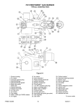
Slow Moving Vehicle Assembly
Figure 1-3
Slow Moving Vehicle
Bundle Assembly
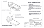
Hydraulic Plumbing
Refer to Figure 1-3:
Install bracket (#1) with hardware shown to bearing cap.
Then install Slow Moving Vehicle (#2) to bracket (#1) by
using screw 1/4" x 5/8" Long (#3) with square nut (#5) and
lock washer (#4).
Refer to Figure 1-4:
The standard cutter is equipped with hydraulic cylinders
for each wing to provide simultaneous folding.
An optional hydraulic lift adjustment kit is also available
from your Dealer.
14102
Hydraulic Plumbing
Figure 1-4
7/14/08
RC45180 & RCM45180 Rotary Cutter 312-382M
9
Table of Contents
Land Pride
Section 1 Assembly and Setup
NOTE: Each pair of outlets on your tractor can only
operate one remote cylinder. All three cylinders on
the cutter are single action (one-way) type cylinders
and should not be plumbed for two-way operation.
Your Dealer will be able to help you determine the best
configuration to match your tractor.
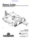
Tractor Hookup
Refer to Figure 1-5:
1. Back the tractor up to the tongue until holes in drawbar and cutter hitch are aligned. Raise or lower tongue
jack to correct height.
2. Attach cutter with 1" hitch pin and secure with lock pin.
Always use a pin that contains a safety locking device
to prevent it from falling out.
3. Lower tongue jack until weight of cutter is fully removed from jack, then remove the jack. Store the jack
on the left hand wing deck. A storage base is located
near the front edge of the wing.
4. Attach safety chain on tongue hitch to tractor. Adjust
chain length to remove all slack except what is necessary to permit turning of the cutter. Lock hook securely
on chain.
Refer to Figure 1-6:
5. The PTO shaft from the tractor may be a constant velocity type or conventional. Attach the 1 3/4-20 splined
end to the input side of the power divider gearbox. Attach end with the quick disconnect to the tractor.
11150
PTO Quick Disconnect
Figure 1-6
NOTE: The PTO quick disconnect consists of a
graphite reinforced, round sleeve that must be rotated about it's own axis to engage/disengage the shaft.
6. Secure chain on PTO around cutter tongue to restrict
outer shield of PTO from rotating.
NOTE: Two small chains are supplied with each
PTO. These chains must be attached to the outer
shields of each PTO shield and to an anchor ring on
the cutter deck or hitch
7. PTO should now be moved back and forth to insure
that it is secured on the shaft of the tractor and power
divider input shaft on the cutter.
8. Should the PTO shaft require shortening:
a. Hold the half shafts next to each other in the shortest working position and mark them.
14103
Tractor Hook-Up
Figure 1-5
10
RC45180 & RCM45180 Rotary Cutter 312-382M
7/14/08
Land Pride
Table of Contents
Section 1 Assembly and Setup
b.
c.
Shorten inner and outer guard tubes equally.
Shorten inner and outer sliding profiles by the
same length as the guard tubes.
d. Proper overlap is a minimum of one-half the
length of each tube, with both tubes being of equal
length.
e. Round off all sharp edges and remove burrs.
Grease sliding profiles.
9. Route cylinder hoses through hose support loop and
connect to tractor remote outlets. Refer to "Hydraulic
Plumbing" on page 9 for proper hookup. If the tractor
being used does not have three pair of supply outlets,
an optional control valve kit is available from your
dealer.
10. Cycle the hydraulic system by raising and lowering the
center deck cylinder and the wing fold cylinders. If operation is sluggish, it may be necessary to purge the
system of trapped air.
!
a. With the wings lowered to the ground, loosen the
hydraulic hose fitting at each wing cylinder slightly
to allow fluid to escape.
b. Slowly activate the tractor control valve to purge
any trapped air from the system.
c. Tighten each fitting.
The optional center deck lift cylinder is purged in the same
manner. The cutter should be lowered to the ground or the
cylinder fully retracted before loosening the hose fitting (as
described above).
11. The PTO Constant Velocity shaft or conventional PTO
(if used) should be checked for adequate clearance
under all ranges of cutter height depending on the
tractor being used. With the PTO shaft attached to the
tractor, slowly raise and lower the cutter to upper and
lower limits while observing clearance distance between hitch and PTO shaft. If an interference condition exists, it may be necessary to modify the drawbar
height/length of the tractor.
DANGER!
Hydraulic fluid under pressure can penetrate skin. Wear protective gloves and safety glasses or goggles when working with hydraulic systems. Use a piece of cardboard or wood rather than
hands when searching for hydraulic leaks. If hydraulic fluid is
injected into the skin, it must be surgically removed within a few
hours by a doctor or gangrene may result.
7/14/08
RC45180 & RCM45180 Rotary Cutter 312-382M
11
Table of Contents
Land Pride
Section 2 Operating Instructions
Section 2 Operating Instructions
Operating Check List
In addition to design and configuration of equipment; hazard control and accident prevention are dependent upon
the awareness, concern, prudence and proper training involved in its operation, transport, maintenance and storage of equipment. Before beginning to operate your
Cutter, the following inspection should be performed.
!
Check
Reference
Read and follow the “Safety Rules” carefully.
Section 1
page 1
Read all of the "Tractor Hook Up" and preparation instructions.
Section 1
page 10
“Operating Instructions” in this Manual
Section 2
page 12
Lubricate the cutter as needed. Refer to
"Lubrication"
Section 5
page 19
Check the cutter initially and periodically for
loose bolts & pins, "Torque Values Chart".
Section 6
page 24
Make sure all guards and shields are in
place.
Section 1
page 3
Gearbox Gear Lube
Section 5
page 20
WARNING!
The following operating procedures should be carried out by
the tractor operator. Other persons should be cleared of the
area even during cutter setup. cutter operation should be
stopped when in the vicinity of other persons.
Refer to Figure 2-1:
1. Raise the center deck to sufficient height to disengage
the transport link (#1) . Remove the transport link pin
(#2), lower the link arm, then replace the link pin to the
storage position.
13885
Transport Link
Figure 2-1
4. Increase throttle to approximately 500 RPM and slowly engage PTO. Ensure that all power shafts are rotating and that cutter has no vibration.
5. Continue to increase throttle to full PTO speed before
commencing forward operation.
Refer to Figure 2-2:
Optimum Ground speed depends on the density of the
material being cut, the horsepower rating of the tractor,
and (in some cases) terrain.
If the cutter-to-tractor PTO is a standard conventional
shaft, avoid tractor-to-cutter turning angles exceeding 35˚.
If equipped with a Constant Velocity PTO shaft, the turning angle may be increased to 80˚. These extreme angles
are intended for intermittent usage only and not prolong
usage. Plan your field cutting to minimize the number of
turns as well as the extreme angles where turns are
necessary.
NOTE: The center deck height is controlled with the
standard ratchet jack or the optional hydraulic lift cylinder.
2. Inspect the wing blade carriers and blades prior to
lowering the wings. The wing deck blades may become locked together (overlapped) when the wings
are raised to transport position. Operating the cutter
under such circumstances will result in severe deck vibration. Inspect the wing decks for a locked blade condition prior to power-on operation. Use a pry bar or
other tool to separate the blades if necessary.
3. The automatic wing latches on each wing must be released prior to lowering the wings. If the wing latch
handles cannot be moved, it may be necessary to
raise the wings to the fully closed position. Release
wing latch and then lower the wings to full-down position.
12
RC45180 & RCM45180 Rotary Cutter 312-382M
11934
Conventional U-Joint PTO
Figure 2-2
7/14/08
Land Pride
Table of Contents
Section 2 Operating Instructions
This cutter was designed to cut grass and medium to
heavy brush in pastures, right-of-ways, and certain ditch/
terrace areas. This cutter is also useful for heavy row crop
cutting. Avoid areas where small trees or brush diameters
exceed 2". Do not attempt to operate this cutter in areas
where rocks, steel, glass, concrete, wire, or other hard,
foreign objects may be present.
!
WARNING!
Do not operate this cutter under any terrain conditions where
the wing angle exceeds 45˚ up. Ensure that the wing wheels are
in continuous ground contact at all times. Use the float position
of your tractors hydraulic system to provide automatic wing
float position for varying terrain conditions.
Refer to Figure 2-3:
6. Engage transport lock (#1) by removing lock pin (#2)
and rotating transport lock to 45˚ position. Insert lock
pin through detent notch and secure with hair pin cotter (#3).
7. Slowly lower the cutter until transport lug of axle weldment contacts transport lock block.
8. Reduce tractor ground speed when turning; be sure
tractor wheel does not contact cutter when turning.
Leave clearance so cutter does not contact obstacles
such as buildings, trees or fences.
9. The cutter should be transported no faster than 15
mph when equipped with laminated or solid tires,
and 30 mph when equipped with pneumatic tires.
Transporting
!
DANGER!
!
CAUTION!
Rotary Cutters have the ability to discharge objects at high
speeds; do not operate this cutter along highways, roadways or
other areas where people may be present unless approved
guarding has been installed and properly maintained. Factory
approved guarding includes front and rear safety chain, deflector skirts or other shields. Contact your dealer or call Great
Plains Manufacturing, Inc. for the name of your nearest factory
authorized dealer.
When traveling on public roads whether at night or during the
day, use accessory light and devices for adequate warning to
operators of other vehicles. Comply with all federal, state and
local laws.
!
CAUTION!
Always disengage tractor PTO before transporting cutter to
avoid injury from thrown objects or blade contact.
1. Select a safe ground travel speed when transporting
from one area to another. When traveling on roadways, transport in such a way that faster moving vehicles may pass you safely.
2. Reduce tractor ground speed when turning. Leave
enough clearance so the cutter does not contact obstacles such as buildings, trees or fences.
3. When traveling over rough or hilly terrain, shift tractor
to a lower gear.
4. Raise cutter to transport position using the hydraulic
lift or rachet jack. Careful: When raising to transport
position, be certain that PTO shaft does not contact
tractor or cutter tongue.
5. Raise both wings to 85˚ vertical position. The automatic wing latches should engage. Check to be sure
they are fully latched.
7/14/08
13885
Transport Link Operation
Figure 2-3
!
CAUTION!
The cutter is 8’ 9" wide and care should be taken when encountering oncoming traffic and roadside obstructions.
Parking
The following steps should be done when preparing to
store the cutter or unhitch it from the tractor. See also
“Storage”, on page 18 for additional information on long
term storage of your cutter.
1. Park the cutter on a level, solid area.
2. Shut off tractor engine and engage parking brake.
3. Install jack & crank up the jack until it is supporting the
unit.
4. Unhitch from tractor.
RC45180 & RCM45180 Rotary Cutter 312-382M
13
Table of Contents
Land Pride
Section 3 Adjustments
Section 3 Adjustments
Center Deck Level Adjustments
These adjustments should be made with the cutter
hooked up to the same tractor that will be used for field operations or one having the same drawbar height.
!
CAUTION!
Engage parking brake, shut off tractor, remove key and disengage PTO before making any height adjustments!
Center Deck Rear Axle
Arms Bolt & Nut Adjustment
NOTE: Cutter is to be set up on level ground with the
wings folded up and in the locked position.
Refer to Figure 3-1:
1. Tighten all four bolts (#1) until the nuts (#2) bottom out
on the bolts (this is to loosen springs up) then loosen
all 4-bolts until all the nuts are loose.
2. Measure the distance "A" on both center axle arm
tubes to axle channel.
3. On the side with the shortest "A" Measurement, tighten nuts up until they are just snug against the axle
tube!
4. Adjust the other axle assembly (with the longest "A"
measurement), by tightening the nuts (#2), until it’s "A"
measurement is the same as the previous axle assembly (with the shortest "A" measurement).
14104
14
RC45180 & RCM45180 Rotary Cutter 312-382M
Center Deck Rear Axle
Figure 3-1
13134
Refer to Figure 3-2:
With the cutter positioned on level ground, the deck should
be adjusted to a level position for the drawbar height of the
tractor being used.
1. Raise both wings to latched position. Adjust the height
of the center deck to 2-3 inch clearance between the
front skids and ground surface.
2. Place a level anywhere on a center deck channel. It
should be oriented for front-to-rear readings.
3. Loosen hex nut (#1) on level rod and turn the leveling
tube weldment (#2) clockwise to raise the front of the
Center Deck Level Adjustments
Figure 3-2
7/14/08
Table of Contents
Land Pride
Section 3 Adjustments
cutter or counterclockwise to lower. Continue to adjust
until the deck is level or the front is slightly below level.
Both leveling rods should be adjusted to equal
lengths.
4. Tighten jam nut (#1) to secure leveling rods.
5. This setting should not require further adjustment unless the drawbar height is changed or different size
tires are used.
6. The cutting height can be adjusted by extending or retracting the hydraulic cylinder or rachet jack located
at the rear center of the cutter.
5. Repeat steps 1 through 4 until axle rockshaft is at level
position.
6. Reattach clevis to rockshaft lug and secure with clevis
pin and cotter pin.
Wing Deck Level Adjustments
The tailwheel adjustment nut, Figure 3-4, is to be adjusted
with wings down and in level position. (Weight of cutter will
set the rubber bumpers). Snug nut up, plus one additional
turn. Bumpers are then set for optimal cushioning
condition!
IMPORTANT: Ensure that Center Deck Level Adjustments
have been made before proceeding with wing deck level
adjustments.
!
CAUTION!
Engage parking brake, shut off tractor, remove key and disengage PTO before making any height adjustments!
Refer to Figure 3-3:
1. Lower both wings to full down position.
2. Place a level on the wing axle rockshaft to determine
initial up or down position (left/right).
3. Raise the wing to full vertical position.
4. Remove the cotter pin (#1) and clevis pin (#2), from
the back end of the axle link (#3). The axle link is then
shortened to raise the wing or lengthened to lower the
wing. Shorten the axle link by rotating the clevis end
clockwise or lengthen by turning counterclockwise.
Reattach to the rockshaft lug.
13887
7/14/08
Wing Deck Tailwheel
Rubber Bumper Adjustment
Refer to Figure 3-4:
NOTE: Cutter to be adjusted on level ground
NOTE: Bumpers will need to be checked periodically
for over-compression. When dimension "A" gets to
1", the cushions should both be replaced. Bumper
part number is 312-313D
13153
Wing Deck Tail Bumper
Figure 3-4
Wing Deck Level Adjustments
Figure 3-3
RC45180 & RCM45180 Rotary Cutter 312-382M
15
Table of Contents
Land Pride
Section 4 Troubleshooting
Section 4 Troubleshooting
Problem
Solution
Oil seal leaking
Drain to level fill hole
Replace seals
Clean off wrapped material and check seal areas daily
Power Take Off yoke
or shock cross failing
Avoid hitting solid objects
Slip Clutches slip even with a light load
Replace clutch plates
Lubricate every 10 hours
Remove foreign object
Bent Power Take Off shaft {Note: Power
Take Off shaft should be repaired or
replaced if bent}
Reduce lift height in transport position
Reposition drawbar
Shorten Power Take Off shaft
Power Take Off shaft
telescoping tube failing
Avoid hitting solid objects
Power Take Off shaft
telescoping tube wearing
Lubricate every 50 hours of operation
Blades wearing excessively
Raise cutting height
Blades coming loose
Tighten blade hardware {refer to “Service Cutting Blades” on page 17}
Blades breaking
Avoid solid objects
Loose blade carrier
Replace gearbox bearings and / or shaft
Tighten shaft nut to specified torque
Blade carrier bent
Avoid hitting solid objects
Excessive side skid wear
Adjust cutter height
Raise cutting height
Excessive vibration
Replace Power Take Off or distribution shaft
Replace blade carrier
Replace blade
Inspect and unlock blades
Disassemble and inspect for incorrectly located needles or damaged bearing cap
Replace each pair of blades on affected carrier
Wing cylinder movement too slow
16
Remove elbow fitting and remove orifice
RC45180 & RCM45180 Rotary Cutter 312-382M
7/14/08
Land Pride
Table of Contents
Section 5 Maintenance and Lubrication
Section 5 Maintenance and Lubrication
Maintenance
Proper servicing and adjustment is the key to the long life
of any farm implement. With careful and systematic inspection, you can avoid costly maintenance, time and repair.
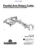
NOTE: Blades for the wings & center deck are 25"
long, Note rotation as shown in Figure 5-1.
For safety reasons, each maintenance operation must be
performed wiht tractor PTO disengaged, the cutter lowered completely to the ground or on safely supported
blocking, tractor engine shut off and ignition key removed.
1. After using your cutter for several hours, check all
bolts to be sure they are tight.
2. After transporting your cutter for several hours, check
all wheel lugs, bolts and nuts to be sure they are tight.
Always maintain proper air pressure in the tires.
NOTE: Check tightness of bolts periodically, using
the “Torque Values Chart” on 24 as a guide.
818-268C
Service Cutting Blades
1. Both blades on each dishpan should be sharpened at
the same angle as the original cutting edge and must
be replaced or reground at the same time to maintain
proper balance in the cutting unit.
IMPORTANT: Replace blades with genuine Land Pride
blades only. If one blade is to be replaced, the mating
blade {on the same carrier} must also be replaced.
NOTE: Do not remove any more material than necessary when sharpening blades.
2. Both blades on each dishpan should weigh the same after sharpening.
3. When replacing or sharpening the cutter blades, examine bolts and hardware for excessive wear and replace if
necessary.
a. Torque blade bolt lock nut to 450 ft. pounds. An extended cheater bar may be required to achieve
proper torque.
b. Carefully check the cutting edges of the blades in relation to the blade carrier rotation diagram below to
ensure correct blade placement.
!
CAUTION!
Installation of the longer blades on the wing decks will cause an
immediate operating hazard.
Blade Rotation
Figure 5-1
4. Blade Dishpan Replacement:
Dishpan nut on gearbox output shafts should be torqued
to 450 foot/pounds and cotter pin installed in nut with legs
securely bent around nut.
Skid Shoe Service & Replacement
The center deck skid shoes should be checked periodically for wear and replaced is necessary. Order center deck
skid shoe Land Pride part #312-218H. No adjustment is
required.
!
CAUTION!
!
WARNING!
Skid shoe replacement must be done with the deck raised to the
transport position and securely blocked. Engage parking brake,
shut off tractor, remove key and disengage PTO before adjusting
or replacing these parts.
Excessive wear on skids may cause inadequate operation of cutter and create a safety hazard!
The wing deck skid shoes should be checked periodically
for wear. Excessive leading edge wear can be repaired by
interchanging the LH wing skid with the RH wing skid. If
both leading edges have been worn down, order skid shoe
Land Pride part # 312-446H.
Skid Shoes
To replace center deck skid shoes:
Refer to Figure 5-2:
a. Attach skid shoe to cutter, using four 1/2" bolts
lock washers and hex nuts.
b. Repeat for opposite skid shoe.
7/14/08
RC45180 & RCM45180 Rotary Cutter 312-382M
17
Table of Contents
Land Pride
Section 5 Maintenance and Lubrication
To replace wing deck shoes:
Refer to Figure 5-3:
a. Attach skid shoe to cutter, using three 1/2" carriage bolts flat washers, lock washers and hex
nuts.
b. Repeat for opposite skid shoe.
Clutch Run-In
Refer to Figure 5-4:
Clutch Run-In
Figure 5-4
10103
The clutch should slip during operation to protect the cutter from excessive loads.
Prior to initial operation and after long periods of inactivity,
the Friction Clutch should be "run-in".
1. Tighten all 4 nuts uniformly until the spring load is low
enough that the clutch slips freely with the PTO engaged.
2. Turn nuts fully back. Clutch is ready for use.
Storage
1. At the end of the working season or when the cutter
will not be used for a long period, it is good practice to
clean off any dirt or grease that may have accumulated on the cutter and any of the moving parts. It may be
necessary to scrape off compacted dirt from the bottom of the deck, then use a garden hose to thoroughly
clean the surface.
2. Check the blades for wear and replace if necessary.
See "Maintenance & Lubrication".
3. Inspect the cutter for loose, damaged or worn parts
and adjust or replace if needed.
4. Lubricate as noted in "Maintenance & Lubrication"
beginning on page 19.
5. Repaint parts where paint is worn or scratched to prevent rust. Aerosol Buckskin touch-up paint is available from your dealer. Order Land Pride part #821011C.
6. Replace all damaged or missing decals.
7. Store the cutter inside if possible. Inside storage will
reduce maintenance and make for a longer cutter life.
Center Deck Skid Shoe
Figure 5-2
14177
Wing Deck Skid Shoe
Figure 5-3
14178
18
RC45180 & RCM45180 Rotary Cutter 312-382M
7/14/08
Table of Contents
Land Pride
Section 5 Maintenance and Lubrication
Lubrication
Lubrication
Legend
Multipurpose
spray lube
Multipurpose
grease lube
Multipurpose
oil lube
50
Intervals at which
lubrication is required
50
Axle Hub Bearing
Repack wheel bearings
Type of Lubrication: Wheel Bearing Grease
Quantity = Coat Generously
13918
NOTE: The tailwheel hub is equipped with a relief hole located directly opposite the grease fitting. The relief hole releases pressure from inside the hub casting when it is greased.
The hub should be greased until grease purges from the relief hole.
50
Wing Hinges (6)
Type of Lubrication: Multi-Purpose
Quantity = As required
14099
As
Required
Ratchet Jack
Type of Lubrication: Multi-Purpose
14176
7/14/08
Quantity = As required
RC45180 & RCM45180 Rotary Cutter 312-382M
19
Table of Contents
Land Pride
Section 5 Maintenance and Lubrication
50
Axle Rockshaft & Axle Link
Type of Lubrication: Multi-Purpose
Quantity = As required
14180
50
Main Hitch
Type of Lubrication: Multi-Purpose
Quantity = As required
14105
50
Gearbox
Type of Lubrication: 80-90W EP
Quantity = As required
NOTE: Do not overfill! Cutter should be level when checking
oil. If, for any reason, all oil has been removed from gearbox,
refill to level plug and allow air to bleed up from lower cavity,
then recheck.
14052
50
Divider Box
Type of Lubrication: 80-90W EP
Quantity = As required
14051
20
RC45180 & RCM45180 Rotary Cutter 312-382M
7/14/08
Land Pride
Table of Contents
Section 5 Maintenance and Lubrication
10
Driveline Shaft
Type of Lubrication: Multi Purpose
Quantity = Coat Generously
14191
25
Drive line Shafts
Type of Lubrication: Multipurpose Grease
12725
8
PTO Constant Velocity Shaft
Type of Lubrication: Multipurpose Grease
NOTE: To extend the life of the constant velocity joint,
extensive lubrication must be performed every 8 hours
of operation!
12726
a. The constant velocity joint should be greased in
a straight position forcing grease through the
passages and into the cavity. After lubrication,
grease should be visible around the ball joints.
b. The constant velocity driveline comes equipped
with a grease zerk in the outer telescoping
member and must be greased every 8 hours to
prevent premature failure of the joint.
c. Grease fittings are located on the u-joints and
driveline shields and should be lubricated every
8 hours of operation.
7/14/08
RC45180 & RCM45180 Rotary Cutter 312-382M
21
Table of Contents
Land Pride
Section 5 Maintenance and Lubrication
4-Plate Slip Clutch
Assembly
NOTE: Before proceeding, secure the clutch firmly in
a vise or other clamping device to prevent injury.
Step 1
Disassembly
Place the hub and friction disks into
the housing.
Step 1
Remove snap ring.
Step 2
Step 2
Remove backup ring, lock collar,
compression spring, bottom backup
ring, and balls.
Compress the Belleville Springs to
the pressure plate by tightening the
four hex nuts and then placing the assembly into the clutch housing.
Step 3
Step 3
Tighten the four hex nuts uniformly
until the clutch pack and hub are
loose.
Bend the retaining lugs inward over
the Belleville Spring edges to secure
the spring before backing the four hex
nuts off.
Step 4
Bend all four retaining lugs out on the
edge of the clutch housing.
Step 4
Step 5
Step 5
Remove the thrust plate with the
Belleville Springs and lug rings to access friction disks and hub for inspection or service.
Insert greased balls.
With the lugs bent in, loosen the four
hex nuts completely to the end of the
threaded studs.
Step 6
Install bottom backup ring, compression spring, lock collar, and top backup ring.
Step 6
Inspect friction disks and hub.
Step 7
14232
22
RC45180 & RCM45180 Rotary Cutter 312-382M
14233
Install snap ring.
7/14/08
Land Pride
Table of Contents
Section 6 Specifications and Capacities
Section 6 Specifications and Capacities
RC45180 & RCM45180 Rotary Cutter
Cutting Width
Overall Width
Minimum Transport Width
180”
190”
96”
Cutting Height
2” - 14”
Overall Length
204”
Deck Material Thickness
Deck Height
Hitch Type
10 gauge
10”
Pull Self - Leveling
Blades - 6 (2 per Carrier)
1/2” x 4” Heat Alloy Steal
Free Swinging
High Lift
Low Friction
Blade Tip Speed
540 RPM PTO:
Center Blade
Wing Blade
1000 RPM PTO:
Center Blade
Wing Blade
Blade Holders
PTO Drive Shafts
Driveline Slippage Protection
Power Divider
FPM
14,853
14,112
RPM
788
907
15,569
14,486
826
930
Center: 3/16” x 27” Oval Pan
Wing: 3/16” x 15” Round Pan
540 PTO: ASAE Category 5 {Input Shafts}
ASAE Category 4 {Output Shafts}
1,000 PTO: ASAE Category 4 {Input / Output}
Dual plate Bellevile type slip clutches on each blade gearbox
540 RPM: PTO Driven 1:1.15 Speed-Up
Tapered Roller Bearings, Beveled Gears
Cast Iron Housing, 125 Horse Power
1000 RPM: PTO Driven 1.3:1 Reduction
Tapered Roller Bearings, Beveled Gears
Cast Iron Housing, 180 Horse Power
Gear Boxes
540 RPM: PTO Driven 1:1.46 Speed-Up
Tapered Roller Bearings, Beveled Gears
Cast Iron Housing, 75 Horse Power
1000 RPM: {wings} PTO Driven 1:1.21 Speed-Up;
{center} 1.21:1 Reduction
Tapered Roller Bearings, Beveled Gears
Cast Iron Housing, 75 Horse Power
Tailwheel - Pull Type
Shock Load Suspension
Machine Weight (With front / rear chain guards)
Tongue Weight
Recommended PTO Horse Power
7/14/08
6.00 x 9 x 21 Laminated or
5 x 15 Rim only or 21” Solid Core or
25.5 x 8.0-14 18 Ply-tube-type
Four Compression type springs on center wheels
Four Rubber Bumper cushions on wing wheels
4,400 lbs.
1,600 lbs.
50 - 150
RC45180 & RCM45180 Rotary Cutter 312-382M
23
Table of Contents
Land Pride
Section 7 Appendix
Section 7 Appendix
Torque Values Chart for Common Bolt Sizes
Bolt Head Identification
Bolt Size
(Inches)
in-tpi1
Grade 2
Grade 5
Bolt Head Identification
Bolt Size
(Metric)
Grade 8
N · m2
ft-lb3
pitch4
N·m
ft-lb
N·m
ft-lb
mm x
1/4" - 20
7.4
5.6
11
8
16
12
M 5 X 0.8
5.8
8.8
10.9
Class 5.8
Class 8.8
Class 10.9
N·m
ft-lb
N·m
ft-lb
N·m
ft-lb
4
3
6
5
9
7
1/4" - 28
8.5
6
13
10
18
14
M6X1
7
5
11
8
15
11
5/16 - 18
15
11
24
17
33
25
M 8 X 1.25
17
12
26
19
36
27
5/16" - 24
17
13
26
19
37
27
M8X1
18
13
28
21
39
29
3/8" - 16
27
20
42
31
59
44
M10 X 1.5
33
24
52
39
72
53
3/8" - 24
31
22
47
35
67
49
M10 X 0.75
39
29
61
45
85
62
7/16" - 14
43
32
67
49
95
70
M12 X 1.75
58
42
91
67
125
93
7/16" - 20
49
36
75
55
105
78
M12 X 1.5
60
44
95
70
130
97
1/2" - 13
66
49
105
76
145
105
M12 X 1
90
66
105
77
145
105
1/2" - 20
75
55
115
85
165
120
M14 X 2
92
68
145
105
200
150
9/16" - 12
95
70
150
110
210
155
M14 X 1.5
99
73
155
115
215
160
9/16" - 18
105
79
165
120
235
170
M16 X 2
145
105
225
165
315
230
5/8" - 11
130
97
205
150
285
210
M16 X 1.5
155
115
240
180
335
245
5/8" - 18
150
110
230
170
325
240
M18 X 2.5
195
145
310
230
405
300
3/4" - 10
235
170
360
265
510
375
M18 X 1.5
220
165
350
260
485
355
3/4" - 16
260
190
405
295
570
420
M20 X 2.5
280
205
440
325
610
450
7/8" - 9
225
165
585
430
820
605
M20 X 1.5
310
230
650
480
900
665
7/8" - 14
250
185
640
475
905
670
M24 X 3
480
355
760
560
1050
780
1" - 8
340
250
875
645
1230
910
M24 X 2
525
390
830
610
1150
845
1" - 12
370
275
955
705
1350
995
M30 X 3.5
960
705
1510
1120
2100
1550
1-1/8" - 7
480
355
1080
795
1750
1290
M30 X 2
1060
785
1680
1240
2320
1710
1 1/8" - 12
540
395
1210
890
1960
1440
M36 X 3.5
1730
1270
2650
1950
3660
2700
M36 X 2
1880
1380
2960
2190
4100
3220
1 1/4" - 7
680
500
1520
1120
2460
1820
1 1/4" - 12
750
555
1680
1240
2730
2010
1 3/8" - 6
890
655
1990
1470
3230
2380
1
in-tpi = nominal thread dia .in inches-threads per inch
N· m = newton-meters
ft-lb= foot pounds
1 3/8" - 12
1010
745
2270
1670
3680
2710
2
1 1/2" - 6
1180
870
2640
1950
4290
3160
3
1 1/2" - 12
1330
980
2970
2190
4820
3560
4 mm
x pitch = nominal thread dia. in millimeters x thread pitch
Tire Inflation Chart
Tire Size
Inflation PSI
25.5 x 8.0” - 14
24
RC45180 & RCM45180 Rotary Cutter 312-382M
35
7/14/08
Warranty
Land Pride warrants to the original purchaser that this Land Pride product will
be free from defects in material and workmanship for a period of one year, from
the date of delivery to the end user, when used as intended and under normal service and conditions for personal use; and 6 months for municipalities, golf courses, sod farms and rental purposes. This Warranty is limited to the replacement of
any defective part by Land Pride and the installation by the dealer of any such replacement part, and does not cover common wear items such as blades, belts,
tines, etc. Land Pride reserves the right to inspect any equipment or parts which
are claimed to have been defective in material or workmanship.
This Warranty does not apply to any part or product which in Land Pride’s judgment shall have been misused or damaged by accident or lack of normal maintenance or care, or which has been repaired or altered in a way which adversely
affects its performance or reliability, or which has been used for a purpose for
which the product is not designed. Misuse also specifically includes failure to
properly maintain oil levels, grease points, and driveline shafts.
Claims under this Warranty must be made to the dealer which originally sold
the product and all warranty adjustments must be made through such dealer.
Land Pride reserves the right to make changes in materials or design of the product at any time without notice.
This Warranty shall not be interpreted to render Land Pride liable for damages
of any kind, direct, consequential, or contingent to property. Furthermore, Land
Pride shall not be liable for damages resulting from any cause beyond its reasonable control. This Warranty does not extend to loss of crops, any expense or loss
for labor, supplies, rental machinery or for any other reason.
No other warranty of any kind whatsoever, express or implied, is made
with respect to this sale; and all implied warranties of merchantability and
fitness for a particular purpose which exceed the obligations set forth in this
written warranty are hereby disclaimed and excluded from this sale.
This Warranty is not valid unless registered with Land Pride within 30 days from
the date of delivery to the end user.
Corporate Office: PO. Box 5060
Salina, Kansas 67402-5060 USA
www.landpride.com