1
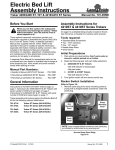
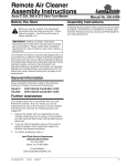
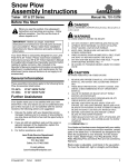
Engine Cold Weather Kit W/Diverter
Assembly Instructions
Treker 4200/4400 NT Series
Before You Start
!
When you see this symbol, the subsequent
instructions and warnings are serious - follow
without exception. Your life and the lives of
others depend on it!
These optional assembly instructions contain only
information required to assemble the Engine Cold
Weather Kit to the NT Series Treker. A detailed
Operator’s Manual was supplied with the Treker. Refer
to the Operator’s Manual for additional specific
information especially information relating to safety
concerns. Also included in the Operator’s Manual is
important information on operation, adjustment,
troubleshooting, and maintenance for this attachment
(some manual sections do not apply to all options).
A separate Parts Manual for replacement parts can be
purchased from your dealer or available free of charge at
www.landpride.com. Have model and serial numbers
handy when placing an order.
Manual Part Numbers:
• Operator’s Manual . . . . . . . . . . . . . . . . . 700-108M
• Parts Manual . . . . . . . . . . . . . . . . . . . . . 700-108P
General Information
This Engine Cold Weather Kit w/Diverter applies to:
Treker 4200/4400 NT Series ............... Kit No. 701-092A
The Engine Cold Weather kit is designed to prevent or
eliminate effects of carburetor icing on the 20hp Honda
engine for Land Pride Trekers. Carburetor icing may occur
at temperatures of 45 degrees Fahrenheit and lower.
Typical symptoms will be loss of power, hard starting,
engine backfiring, plug fouling, gas in the oil, or engine
stalling. Application of this kit will force warm air directly
into the air intake filter reducing or eliminating the icing
condition and its related symptoms. Vehicles started at
freezing temperatures should be allowed to warm-up for
approximately 4-5 minutes prior to full vehicle operation.
When outdoor temperatures are consistently above 45
degrees Fahrenheit, the air bypass valve should be turned
to the summer setting to bypass air away from the engine
exhaust manifold or a noticeable power loss will occur.
The oil and filter must be changed if plugs have become
fouled and if the dipstick indicates an oil overfill condition
with gas in the oil. Do not overfill engine with oil or plug
fouling will likely reoccur.
Tools required:
• 3/8" Nut driver & drill
• 1/2” Wrench or socket and driver
© Copyright 2005
11/23/05
Manual No. 701-094M
• 9/16" Wrench or socket and driver
• 13 mm Socket
• Straight blade screwdriver
• Cross blade screwdriver
• Knife
Assembly Instructions
A detailed listing of parts for Kit No. 701-092A is
provided on page 3. Use the list as a checklist to
inventory parts received.
Initial Preparations
!
CAUTION!
Securely support cargo box in the up position to prevent
injury when working under the cargo box.
1. Park vehicle on a flat surface, move gear shift lever to
neutral, set park brake, and chock front and back of
the right rear wheel to prevent the vehicle from
rolling.
2. Raise cargo box fully up and securely support it in
the up position to prevent injury while working
around the engine.
3. Turn off engine and remove ignition key.
Refer to Figure 1:
4. Loosen the two worm drive hose clamps securing the
rubber air intake hose and save for reuse.
5. Remove rubber air intake hose and save for
modification and reinstallation.
NOTE: It is not necessary to disconnect engine
snorkel and snorkel hose.
SS Hose
Clamp
Air Cleaner
Canister
Rubber Air
Intake Hose
21127
Existing Air Intake Assembly
Figure 1
Manual No. 701-094M
1
Land Pride
Assembly Instructions
Air Intake Installation
Refer to Figure 3:
1. Refer to air hose (#1A). Cut one end of existing air
intake hose to 4 1/4" long.
1. Orient air diverter assembly (#5) as shown.
2. Slip two worm drive hose clamps (#9) over the
air intake hose (#1A). Insert air hose (#1A) over the
air intake nozzle (#8) and over the air diverter (#5)
nozzle. Do not tighten hose clamps.
3. Refer to air hose (#1B). Measure the distance
between the diverter assembly (#5) nozzle to the air
filter inlet nozzle (#10). Add 2" to this distance and
cut the other end of the air intake hose to this length.
4. Slip two worm drive hose clamps (#9) over the cut to
length air intake hose (#1B). Insert air intake hose
(#1B) over air diverter (#5) nozzle and air intake
nozzle of air filter canister (#12). Do not tighten hose
clamps.
5. Expand the flexible heat riser tube (#3) to
approximately 30". Be careful not to deform the tube
while expanding it.
Air Bypass Handle
Summer
Position
Winter
Position
Air Bypass
Handle
Air Bypass handle Position (Summer Position Shown)
Figure 4
Throttle Heat Shield Installation
Refer to Figure 5:
1. Remove M8 hex flange cap screw (#5) from engine
stabilizer bracket.
1. Position heat shield cover assembly (#1) onto engine
housing as shown. Make certain the heat shield is
positioned under the engine stabilizer bracket.
2. Secure heat shield with two 1/4" x 1/2" phillips head
machine screws (#3), two 5/16" x 1 1/4" hex flange
head screws (#4) and replace the M8 hex flange cap
screw (#5).
3. Torque 1/4" phillips heads machine screws to 5.6 ft.
lbs, 5/16" hex head screws to 17 ft. lbs. and M8 hex
cap screws to 19 ft. lbs.
4. Warm air cover (#2) should be secured over the heat
shield opening when temperatures are below 45
degrees Fahrenheit and over the warning decal
when temperatures are above 45 degrees
Fahrenheit.
Stabilizer
Bracket
22441
Air Intake Installation
Figure 3
6. Slip two worm drive hose clamps (#9) over the
flexible heat riser tube (#3). Insert flexible heat riser
tube (#3) over air diverter (#5) nozzle and heat tube
weldment (#2). Do not tighten hose clamps.
7. Clamp heat tube weldment (#2) to engine exhaust
manifold (#4) with 2" U-bolt (#14), clamp plate (#6)
and 3/8" hex nuts (#13). Torque nuts to 20 ft. lbs.
8. Tighten all six worm drive hose clamps (#9).
Refer to Figure 4:
9. Rotate the air bypass handle counter clockwise to
the winter position marked with a “W” when
temperatures are below 45 degrees Fahrenheit.
Rotate the air bypass handle clockwise to summer
position marked with a “S” when temperatures are
above 45 degrees Fahrenheit.
2
Manual No. 701-094M
22451
Heat Shield Installation
Figure 5
■
11/23/05
Land Pride
Listing of Parts
Kit No. 701-092A
ENGINE COLD WEATHER KIT W/DIVERTER 00NT
Qty.
Part No.
Part Description
1
1
1
1
1
1
4
700-204H
700-226S
700-258S
700-267D
700-271D
701-094M
800-259C
HEAT TUBE WELDMENT
AIR DIVERTER ASSEMBLY NT
HEAT SHIELD COVER SUB-ASSY NT
CLAMP PLATE
2" HEAT RISER TUBE 36.0" LG
ENGINE COLD WEATHER KIT MANUAL 00NT
CLAMP WORM DRIVE #36SS (1.81-2.75)
11/23/05 ■
Manual No. 701-094M
3
Corporate Office: P.O. Box 5060
Salina, Kansas 67402-5060 USA
www.landpride.com