1
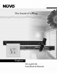
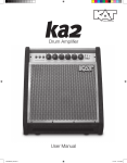
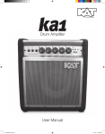
OWNER’S MANUAL
Profile System Two
TM
Congratulations on the purchase of your new Kustom Profile System Two; a portable
and powerful stereo P.A. System. Your new system offers unsurpassed sound quality
as well as outstanding performance characteristics. Inside this manual you’ll find
detailed information regarding the system’s many features. We wish you many years
of enjoyment with your Kustom Profile System Two.
ENGLISH
IMPORTANT SAFETY INSTRUCTIONS
1.
Danger
Exposure to extremely high noise levels may cause a
permanent hearing loss. Individuals vary considerably to
noise induced hearing loss but nearly everyone will lose
some hearing if exposed to sufficiently intense noise for a
sufficient time.
2.
3.
4.
5.
The U.S. Government's Occupational Safety and Health
Administration (OSHA) has specified the following
permissible noise level exposures:
DURATION PER DAY (HOURS)
8
6
SOUND LEVEL (dB)
90 93 95 97 100 103
6.
7.
4 3 2 1
8.
According to OSHA, any exposure in the above permissible
limits could result in some hearing loss. Ear plugs or
protectors in the ear canal or over the ears must be worn
when operating this amplification system in order to prevent
a permanent hearing loss. If exposure in excess of the limits
as put forth above, to insure against potentially harmful
exposure to high sound pressure levels, it is recommended
that all persons exposed to equipment capable of inducing
high sound pressure levels, such as this amplification
system, be protected by hearing protectors while this unit is
in operation.
9.
10.
11 .
12.
CAUTION
RISK OF ELECTRIC SHOCK
DO NOT OPEN
CAUTION: TO REDUCE THE RISK OF ELECTRIC SHOCK, DO
NOT REMOVE CHASSIS. NO USER-SERVICEABLE
PARTS INSIDE. REFER SERVICING TO QUALIFIED
SERVICE PERSONNEL.
Read all safety and operating instructions before using this
product.
All safety and operating instructions should be kept for
future reference.
Read and understand all warnings listed on the operating
instructions.
Follow all operating instructions to operate this product.
This product should not be used near water, i.e. Bathtub,
sink,swimming pool, wet basement, etc.
Only use dry cloth to clean this product.
Do not block any ventilation openings, It should not be
placed flat against a wall or placed in a built-in enclosure
that will impede the flow of cooling air.
Do not install this product near any heat sources ;such
as,radiators, heat registers, stove or other apparatus
(including heat producing amplifiers) that produce heat.
Do not defeat the safety purpose of the polarized or
grounding-type plug. A polarized plug has two blades with
one wider than the 0ther.A grounding-type plug has two
blades and a third grounding prong. The wide blade or the
third prong are provided for your safety If the provided plug
does not fit into your outlet, consult an electrician for
replacement of the obsolete outlet.
Protect the power cord being walked on or pinched,
particularly at Plugs, convenience receptacles and the point
where they exit from the apparatus. Do not break the ground
pin of the power supply cord.
Only use attachments specified by the manufacturer.
Use only with the cart, stand, tripod, bracket,
or table specified by the manufacturer or
sold with the apparatus. When a cart is
used, use caution when moving cart/
apparatus combination to avoid injury
from tip-over.
Unplug this apparatus during lightning storms or when
unused for long periods of time.
Care should be taken so that objects do not fall and liquids
are not spilled into the unit through the ventilation ports or
any other openings.
Refer all servicing to qualified service personnel. Servicing
is required when the apparatus has been damaged in any
way; such as, power-supply cord or plug is damaged, liquid
has been spilled or objects have fallen into the apparatus,
the apparatus has been exposed to rain or moisture, does
not operate normally or has been dropped.
WARNING: To reduce the risk of fire or electric shock, do not
expose this apparatus to rain or moisture.
S3125A
AVIS: RISQUE DE CHOC ELECTRIQUE-NE PAS OUVRIR.
13.
THIS SYMBOL IS INTENDED TO ALERT THE USER TO THE PRESENCE
OF NON-INSULATED "DANGEROUS VOLTAGE" WITHIN THE
PRODUCT'S ENCLOSURE THAT MAY BE OF SUFFICIENT MAGNITUDE
TO CONSTITUTE A RISK OF ELECTRIC SHOCK TO PERSONS.
14.
15.
THIS SYMBOL IS INTENDED TO ALERT THE USER TO THE PRESENCE
OF IMPORTANT OPERATING AND MAINTENANCE (SERVICING)
INSTRUCTIONS IN THE LITERATURE ACCOMPANYING THE UNIT.
APPARATUS SHALL NOT BE EXPOSED TO DRIPPING OR SPLASHING
AND THAT NO OBJECTS FILLED WITH LIQUIDS, SUCH AS VASES,
SHALL BE PLACED ON THE APPARATUS.
16.
2
IMPORTANTES INSTRUCTIONS DE SECURITE
FRENCH
1. Lire avec attention toutes les recommandations et précautions
d'emploi avant d'utiliser ce produit.
2. Toutes les recommandations et précautions d'emploi doivent
être conservées afin de pouvoir s'y reporter si nécessaire.
3. Lire et comprendre tous les avertissements énumérés dans les
précautions d'emploi.
4. Suivre toutes les précautions d'emploi pour utiliser ce produit.
5. Ce produit ne doit pas être utilisé près d'eau, comme par
exemple baignoires, éviers, piscine, sous-sol humides ... Etc.
6. Utiliser exclusivement un chiffon sec pour nettoyer ce produit.
7. Ne bloquér aucune ouverture de ventilation. Ne pas placer le
produit tout contre un mur ou dans une enceinte fernée, cela
gênerait le flux d'air nécessaire au refroidissement.
8. Ne pas placer le produit près de toute source de chaeur telle
que radiateurs, arrivées d'air chaud, fourneaux ou autres
appareils générant de la chaleur (incluant les amplificateurs
producteurs de chaleur) .
9. Ne pas négliger la sécurité que procure un branchement
polarisé ou avec raccordement à la terre, Un branchement
polarisé comprend deux fiches dont l'une est plus large que
l'autre. Un branchement à la terre comprend deux fiches plus
une troisième reliée à la terre. Si la fiche secteur fournie ne
s'insert pas dans votre prise de courant. consulter un
'électricien afin de remplacer votre prise obsolète.
10. Protéger le cordon d'alimentation de tout écrasement ou
pincement, particulièrement au niveau des fiches, des
réceptacles utilisés et à l'endroit de sortie de l'appareil. Ne pas
casser la fiche de terre du cordon d'alimentation.
11. Utiliser uniquement les accessoires spécifiés par le
constructeur.
12. Utiliser uniquement avec le chariot de
transport, le support, le trépied, la
console ou la table spécifiés par le
constructeur ou vendus avec l'appareil.
Lors de l'utilisation d'un chariot, bouger
avec précaution l'ensemble chariotlappareil
afin d'éviter les dommages d'un renversement.
13. Débrancher cet appareil lors d'orages ou s'il n'est pas utilisé
pendant une longue période.
14. Des précautions doivent être prises afin qu'aucun objet ne
tombe et qu'aucun liquide ne se répande à l'intérieur de
l'appareil par les orifics de ventilation ou n'importe quelle autre
ouverture.
15. Pour toutes interventions techniques s'adresser à un
technicien qualifié.L'intervention technique est nécessaire
lorsque l'appareil a été endommagé de n'importe quelle façon,
comme par exemple si le cordon secteur ou sa fiche sont
détériorés,si du liquide a coulé ou si des objets sont tombés à
l'intérieur de l'apparei1,si l'appareil a été exposé à la pluie ou à
l'humidité, s'il ne fonctionne pas normalement ou s'il est tombé.
16. ATTENTI0N:Pour réduire le risque d'incendie ou de choc
electrique ne pas exposer l'appareil à la pluie ou à l'humidité.
Danger
L‘exposition a des niveaux eleves de bruit peut provoquer
une perte permanente de l’audition, Chaque organisme
humain reagit differemment quant a la perte de l’audition,
mais quasiment tout le monde subit une diminution de
I’acuite auditive lors d’une exposition suffisamment
longue au bruit intense. Les autorites competentes en
reglementation de bruit ont defini les expositions tolerees
aux niveaux de bruits:
DURE EN HEURES PAR JOUR
8
6
4 3 2 1
INIVEAU SONORE CONTINU EN dB
90 93 95 97 100 103
Selon les autorites, toute exposition dans les limites
citees ci-dessus,peuvent provoquer certaines pertes
d’audition. Des bouchons ou protections dans l’appareil
auditif ou sur l’oreille doivent etre portes lors de
l’utilisation de ce systeme d’amplification afin de prevenir
le risque de perte permanente de l’audition, Dans le cas
d’expositions superieures aux limites precitees il est
recommande, afin de se premunir contre les expositions
aux pressions acoustiques eIevees potentielIement
dangeureuses, aux personnes exposees aux
equipements capables de delivrer de telles puissances,
tels ce systeme d’amplification en fonctionnement, de
proteger l’appareil auditif.
ATTENTION
RISQUE DE CHOC ELECTRIQUE
NE PAS OUVRIR.
S3125A
ATTENTION: AFIN DE LlMlTER LE RISQUE DE CHOC ELECTRIQUE,
NE PAS ENLEVER LE CHASSIS. NE CONTIENT PAS DE
PIECES POUVANT ETRE REPAREE PAR L’UTILISATEUR.
CONFIER LE SERVICE APRES-VENTE AUX
REPARATEURS AGREES.
CE SYMBOLE A POUR BUT D'AVERTIR L'UTILISATEUR DE LA PRESENCE
DE VOLTAGE DANGEREUX NON-ISOLE A L'INTERIEUR DE CE PRODUIT
QUI PEUT ETRE DE PUISSANCE SUFFISAMMENT IMPORTANTE POUR
PROVOQUER UN CHOC ELECTRIQUE AUX PERSONNES.
CE SYMBOLE A POUR BUT D'AVERTIR L'UTILISATEUR DE LA PRESENCE
D'INSTRUCTIONS D'UTILISATION ET DE MAINTENANCE DANS LES
DOCUMENTS FOURNIS AVEC CE PRODUIT.
AFIN DE REDUIRE LES RISQUÉ D'INCENDIE ET DE DECHARGE
ELECTRIQUE, NE PAS EXPOSER CET APPAREIL A LA PLUIE OU A
L'HUMIDITE.
3
Table of Contents
Profile System Two Contents
Optional Accessories
Profile System Two Features
Setup Diagram A - Mixer Front
Setup Diagram B - Mixer Back
Setup Diagram C - Speaker Cabinet Back
Setup Instructions
About the Master Section
About the Input Section
About the Output Section
FAQ Frequently Asked Questions
Amplifier Loading Chart
Block Diagram
Specifications
EC Declaration of Conformity
Kustom Contact Information
4
5
5
5
6
7
8
9
10
11
14
15
16
17
18
19
20
Profile System Two Contents
These items are included with your Profile System Two:
• (1) 300-Watt Stereo Powered Mixer
• (2) Line Array Speaker Cabinets
• (2) 25-Foot Speaker Cables
• Owner’s Manual
• Warranty Card
Optional Accessories:
• Convenient Roller Bag for Easy Transport (KPSRB220)
• Kustom Profile Stands for Speakers & Mixer (KPSSS200)
• Kustom Profile Microphone with accessories (KPS-DM120)
Profile System Two Features
Profile Two Powered Mixer
• Power: 300 Watts RMS Total - 150 Watts Per Channel (Stereo)
• 8-Band Master EQ With Sub-Frequency/Subwoofer Control
• 6 Channels (5 Balanced XLR & 1/4” Combo Inputs, 1 Auxiliary Channel)
• Stereo Input on 5th Channel
• Instrument-Ready Preamp on 5th Channel
• 2-Band EQ (Bass & Treble) controls per channel
• Monitor Volume Control Per Channel
• Stereo Panning Control Per Channel
• Discrete Stereo AUX Channel with 2-Band EQ
• Stereo Mic-In and Line-In Inputs (1/8”) on AUX Channel
• 24-Bit Digital Effects Processor with 16 Effects
• Exclusive Double Take Vocal Double Track Simulator
• Phantom Power
• Effects Loop
• Mounts on optional Kustom Profile Stand (KPSSS200)
TM
Profile Two Speakers
• Two Heavy-Duty 8” Speakers per Enclosure
• One Neodymium Compression Driver with 1” Exit per Enclosure
• Line Array Technology for Focused Dispersion
• Mounts on optional Kustom Profile Stand (KPSSS200)
5
SETUP DIAGRAM A
MIXER FRONT
6
SETUP DIAGRAM B
MIXER BACK
7
SETUP DIAGRAM C
SPEAKER CABINET BACK
Speaker Input Jack (Y)
This jack is used to connect the Speaker Output Jack (R or W) to the speaker. This should be
connected with a good quality speaker cable.
8
Setup Instructions:
Making Connections:
• Using the Profile speaker cables, or a set of your own, connect an end of each cable into the
speaker outputs of the mixer (R & W). Then connect the opposite end of each cable to the
appropriate speaker cabinet input (Y). Hint: For ease of use, connect the right output jack (R) to the
speaker cabinet on the right side of the mixer front and connect the left output jack (W) to the
speaker cabinet on the left side of the mixer front. Doing this will ensure that the pan control (E) will
be in sync with the appropriate speaker.
• If you are using a powered monitor, connect the input of the powered monitor to the monitor output
jack (T) on the back of the mixer.
• If you are using a powered subwoofer, connect the input of the powered subwoofer to the sub output
jack (U) on the back of the mixer.
• Be sure that the power switch (S) is set to the “off” position and then attach the AC cable to the AC
input jack (X).
• Plug in the microphones and instruments you plan to use into the mic/line combination jacks (L & M).
Note: If you are using an instrument that has a stereo output connect that one to the mic/line
combination jack on channel 5 (M) using a stereo (tip/ring/sleeve) cable. If you are using a passive
acoustic instrument, you should use the mic/line combination jack on channel 5 (M) and set the
inst/line switch (H) to the inst position.
• If you are using an audio source, such as a CD player or computer, connect the output of the source
to the RCA input jacks (I) or the line input jack (J).
• If you are using a microphone with a mini (1/8”) plug, you can use the mic in jack (K) to connect to
the mixer.
Master Section:
• Turn the master volume control (3) and the monitor volume control (5) counter-clockwise to the
lowest setting.
• Set the master equalizer controls (2) to their center positions (0dB).
• If you are not using a subwoofer, set the sub volume to the center position. If you are using a
subwoofer, set the sub volume to its lowest position.
• Turn the effects volume control (6) counter-clockwise to the lowest setting.
Input Section:
•
•
•
•
•
Turn all volume controls (G) counter-clockwise to their lowest positions.
Set the pan controls (E) to their 12 o’clock positions.
Set the treble and bass controls (C & D) to their 12 o’clock positions.
Turn the monitor controls (B & F) counter-clockwise to their lowest positions.
Turn the effects controls (A) counter-clockwise to their lowest positions.
Playing:
• Turn the power switch (S) to the “on” position. Note: The power indicator (4) on the front of the
mixer should now be lit.
• Turn the master volume control (3) clockwise to the 9 o’clock position and begin adjusting the
volume controls (G) of the individual channels (that you are using) clockwise to reach desired level.
After you are happy with the basic level, you then use the master volume control (3) to increase or
decrease the overall amount of volume. Note: If you are using a powered subwoofer, adjust the sub
volume slider (1) to the center position. After setting the basic level, you can then adjust this control
to increase or decrease the output of the powered subwoofer.
• Adjust the treble and bass controls (C & D) on the individual channels and the master equalizer
controls (2) to achieve the desired sound.
• Turn the master effects volume control (6) clockwise to the 9 o’clock position and begin adjusting the
effects controls (A) on the individual channel to achieve the desired amount of digital effects for each
channel. Note: You should also turn the effects selector control (7) to the desired effect selection
and press the effects active switch (0) to the “on” position.
9
About the Master Section
The master section gives you final control over the sum of what is happening in the input section. In other
words, the adjustments you make in this section will affect all channels evenly.
Sub Volume Control (1)
When using a powered subwoofer that is connected into the sub output jack (U), this control
becomes a volume control for the subwoofer. The output signal level can be adjusted by + or 12dB.
When not using a powered subwoofer, this control becomes part of the equalizer section. This
control will adjust the sub frequencies by + or - 12dB.
Equalizer Controls (2)
These controls are used to adjust the sound to your taste. The individual frequencies (100Hz,
250Hz, 500Hz, 1KHz, 2KHz, 4KHz, 10KHz) can be adjusted by + or - 12dB.
Master Volume (3)
This control is used to adjust the overall output volume of the mixer. Adjusting this control will also
adjust the output of the sub output jack (U) when a powered subwoofer is used. Although the sub
volume control (1) will still adjust the output level up or down.
Power Indicator (4)
This indicator will light when power is applied to the amplifier.
Monitor Volume (5)
This control will adjust the overall output volume going to the monitor output jack (T).
Effects Volume (6)
This control will adjust the overall amount of effects that will be mixed into the outputs.
Effects Selector Switch (7)
This switch is used to select the type of digital effect you want to use. There are 16 different digital
effects to choose from. These are the available effects:
Reverb:
Small Room
Medium Room with Pre Delay
Large Room
Large Hall
Plate Reverb
Chorus:
Chorus Slow
Chorus Fast
Double Take/Chorus
Delay:
Doubler
Slapback
Echo
Delay 400ms
Double Take
Combos:
Double Take/Reverb
Chorus/Reverb
Chorus/Delay/Reverb
TM
Effects To Record Out Switch (8)
This push button switch is used to send effects to the record out jacks (V) on the back of the mixer.
Effects To Monitor Switch (9)
This push button switch is used to send effects to the monitor out jack (T) on the back of the mixer.
Effects Active (0)
This push button switch is used to activate the digital effects. When this switch is set to the “off”
position the effects will be bypassed.
10
About the Input Section
The input section is where you connect microphones, guitars, drum machines, keyboards, and other audio
sources.
Effects Control (A)
This control is used to send the signal from the individual channel to the digital effects. The effects
volume control (6) adjusts the overall volume for this control.
Monitor Control (B)
This control is used to send the signal from the individual channel to the monitor output jack (T).
The monitor volume control (5) adjusts the overall volume for this control.
Treble Control (C)
This control is used to adjust the amount of “high” frequency applied to the individual channel.
Bass Control (D)
This control is used to adjust the amount of “low” frequency applied to the individual channel.
Pan Control (E)
This control is used to send the signal from the individual channel to the left and/or right outputs of
the mixer. Setting this control to the 12 o’clock position will send signal equally to both left and right
outputs.
Aux Monitor Control (F)
This control will adjust the overall amount of input signal from the Aux channel that is sent to the
monitor output jack (T).
Volume Control (G)
This control will adjust the overall amount of input signal of the individual channel that is sent to the
Master Volume Control (3).
Instrument/Line Switch (H)
If you are using a string instrument, such as an acoustic guitar that has a passive pickup (nonbattery powered) or an electric guitar without an amp, then you should connect it to channel five and
set this switch to instrument (“inst”). Setting the switch to instrument alters the equalization of the
channel to bring out the sweet frequencies of any string instrument, such as acoustic and electric
guitar, mandolin, cello, violin, or other stringed instruments.
RCA Input Jacks (I)
These jacks are used to connect any audio device that uses the RCA type plugs. Note: There are
left and right inputs which are automatically kept stereo through the entire system. Basically, what is
connected to the left input will come out of the left speaker. The same is true for the right.
Aux Line In Jack (J)
This jack accepts a stereo (tip/ring/sleve) 1/8” plug. This should be used to connect a device with a
line level output such as a CD player or computer.
Mic In Jack (K)
This jack can be used to connect a microphone that has a 1/8” plug such as a computer microphone.
This jack has phantom power for microphones that require it.
Combination Input Jacks (L)
These jacks are used to connect any audio source to the mixer, such as microphones, guitars,
keyboards, drum machines, CD players, etc. These mono jacks will accept either 1/4” plugs or XLR
type plugs.
11
Methods for connecting inputs to channels
Method 1: Microphone using XLR balanced inputs This is the most popular method for connecting microphones. It works with both dynamic and condenser low
impedance microphones. Acoustic guitars that have XLR balanced outputs can also use this input. Because of the
phantom power on these inputs, a battery
may not be needed. Check the
2 1
3
manufacturer of your instrument for use
without a battery.
MICROPHONE
BALANCED MIC CABLE
CH 1~5 INPUT
Method 2: Line level instrument using line input and a hi-z instrument cableThis method uses the mono line output through a hi-z instrument cable.
Pros: A quick simple way to get an instrument into the PA without special cables or adapters. This method gives
good results in most situations for short distances.
Cons: Using an un-balanced cable longer than 25 feet runs the risk
of hum and noise. Using this method in CH5 does not take
Line Out
advantage of its full stereo input feature.
Right Left (mono)
1/4” MONO INSTRUMENT CABLE
LINE LEVEL INSTRUMENT
CH1~5 INPUT
Method 3: instrument with passive pickup using hi-z input and cable (CH 5 only)This method uses the hi-z (hi impedance) feature of channel 5. For best results, have the inst/line switch in
the instrument (pressed in) position. This channel will automatically switch to mono mode using this method.
Pros: A quick simple way to get a low output passive
pickup instrument into the PA without special battery
powered adapters.
Cons: You run the risk of hum, noise and de-graded signal
if cables longer than 15 feet are used.
CH 5 INPUT
1/4” MONO INSTRUMENT CABLE
Method 4: CD/MP3, computer etc. using aux line in-
INSTRUMENT WITH PASSIVE PICKUP
AUX
DEVICE’S
This method is for connecting devices that have 1/8” stereo or RCA line level outputs. The stereo
separation of the device is maintained throughout the system. Headphone outputs can also be used as
long as the level is kept low enough to prevent overloading the input. It is OK to use all three aux inputs at
once.
Pros: Provides a quick simple way to get pre-recorded music
1/8” STEREO CABLE
into the PA. All three of the aux inputs can be used together.
Cons: Right/left panning (balance) must be done with the input
LINE INPUTS
device.
RCA STEREO CABLE
Method 5: Unbalanced condenser mic with 1/8” plug
This method is for connecting 1/8” mono or stereo condenser microphones typically used with computers. The ring and
tip are typically tied together on mono microphones. The phantom supply is less voltage than the other Mic inputs.
Pros: Provides a quick simple way to connect small Mics. The other two aux inputs can be used together with this mic
input so in a way, it’s like getting an extra Mic channel.
MICROPHONE
Cons: Caution must be taken to not create feedback in the system
1/8” STEREO CABLE
with this type of Mic. There are many low quality microphones of this
type that offer little or no feedback rejection.
MIC IN
12
About the Input Section (Cont.)
Combination Input Jack (M)
This jack functions the same as the other combination jacks (L) except the 1/4” input can be stereo,
mono, or hi-Z mono. String instruments, such as acoustic guitar that have a passive pickup (nonbattery powered) are typically hi-z mono and will work best in this channel. Line level stereo
instruments such as electronic keyboards and drum machines are excellent choices for this channel,
because it maintains the instrument’s stereo signal through the two separate preamps of channel 5.
There is no need to be concerned if the instrument is stereo or mono because the channel
automatically switches to mono if no signal is present on the ring of the 1/4” input, or if a standard
mono guitar cord is used. In the stereo mode, the tip is assigned to the left preamp and the ring to
the right preamp of channel 5. When no signal is present on the ring, or if a mono 1/4" plug is used,
the signal present on the tip will be assigned to both left and right preamps of channel 5.
Methods for connecting instruments to channel 5
Method 1: Stereo using individual left and right line outputs of an electronic instrument -
Tip
Rin (left)
g(
Sle Righ
t)
ev
e(
Sh
iel
d
)
This method maintains stereo integrity from the instrument to speakers taking full advantage of the stereo feature
channel 5 offers.
Pros: Delivers a full rich sound on instruments with stereo effects.
Cons: May require a 1/4” Stereo Adapter wire if
your instrument does not have a single stereo
Line Out
jack.
KEYBOARD
Headphone
Right Left (mono)
(or similar electronic instrument)
Right
RING
TIP
Left
CH 5 INPUT
1/4” STEREO ADAPTER
1/4” INSTRUMENT CABLES
Method 2: Stereo using Headphone outputThis method gives the same result as the first method with a single cable. The headphone volume on the
instrument should set for a good mix in the PA when channel 5 volume is half way up. If the headphone volume is
too high, it can overload channel 5 and sound distorted.
Pros: Same as method 1 but with less clutter.
Cons: The musician playing the instrument
Line Out
must remember that too much headphone level
Headphone
Right Left (mono)
can distort the channel.
Tip
Rin (le)ft
g(
Sle Righ
t)
ev
e(
Sh
iel
d
)
KEYBOARD
CH 5 INPUT
(or similar electronic instrument)
1/4” STEREO INSTRUMENT CABLE
CH 5 INPUT
(Sh
ie
ve
Sle
e
Tip
(le
ft)
ld )
Method 3: Mono using mono Line out This method uses the mixed stereo signal of the instrument. This method can also be used on channels 1~4.
Pros: If this is a multi-instrument keyboard, there will be a balanced mix of the instruments in both speakers.
Cons: This method does not take advantage of
the stereo feature unique to channel 5.
Line Out
KEYBOARD
Headphone
(or similar electronic instrument)
1/4” STEREO INSTRUMENT CABLE
13
Right Left (mono)
About the Output Section
The output section (mixer back) is where you connect your speakers, recording equipment, and any other
external sound conditioning device.
Left Preamp Output (N)
This jack can be used to connect the left output to an external audio device such as a power amp.
This output is line level.
Right Preamp Output (O)
This jack can be used to connect the right output to an external audio device such as a power amp.
This output is line level.
Left Power Amp Input (P)
This jack can be used to connect an external line level audio device directly to the left power amp.
Note: When this jack is used, the signal from the mixer will no longer be going to the left power amp.
The Left Preamp Output (N) and this jack can be used together to place a sound conditioning
device, such as an equalizer, directly in line with the left channel of the mixer. The preamp out
should be connected to the input of the device and the output of the device should be connected to
this jack.
Right Power Amp Input (Q)
This jack can be used to connect an external line level audio device directly to the right power amp.
Note: When this jack is used, the signal from the mixer will no longer be going to the right power
amp. The Right Preamp Output (O) and this jack can be used together to place a sound
conditioning device, such as an equalizer, directly in line with the right channel of the mixer. The
preamp out should be connected to the input of the device and the output of the device should be
connected to this jack.
Right Speaker Output (R)
This jack is used to connect the right speaker to the mixer. Note: This should be the speaker that is
on the right side of the mixer front. The right on the Pan Control (E) will then correspond to the right
speaker.
Power Switch (S)
This switch is used to apply AC power to the mixer.
Monitor Output (T)
This jack is used to connect an external power amp or powered monitor to the mixer. The overall
output of this jack is controlled by the Monitor Volume Control (5).
Sub Output (U)
This jack is used to connect a powered sub woofer to the mixer. When using this jack the Sub
Volume Control (1) will adjust the level of output to the sub woofer.
RCA Record Out Jacks (V)
These output jacks are used to send a line level signal to any audio device that uses the RCA type
plugs for an input. These can be used to record directly from the mixer.
Left Speaker Output (W)
This jack is used to connect the left speaker to the mixer. Note: This should be the speaker that is
on the left side of the mixer front. The left on the Pan Control (E) will then correspond to the left
speaker.
AC Input Jack (X)
This jack is used to connect AC power to the Profile System Two.
14
FAQ Frequently Asked Questions:
1. How many speakers can I use with the Profile Two?
ANSWER: Most speaker cabinets today are 8-ohms.
For the sake of this question we will assume this is the
case. You can use a total of four 8-ohm speakers with
the Profile Two: Two for the Left power-amp and two
for the Right power-amp. The Profile Two cabinets are
4-ohms each. DO NOT connect more than one of these
cabinets per power-amp. DO NOT plug more than two
8-ohm speakers or one 4-ohm speaker into each poweramp.
7. I get this nasty pop when turning the microphone
switch on or off. What’s wrong?
ANSWER: The microphone or cord is probably wired
incorrectly or uses the wrong type of cable. The pop
occurs when the phantom supply on a channel is
shorted to shield ground. A properly wired XLR cord
uses 2 conductor shielded cable. The shield connects
to pin 1 and the center conductors go to pins 2 and 3.
There cannot be a jumper or short between pins 2, 3,
and the shield. The microphone is wired correctly
when the signal on pin 2 and 3 short to each other
when switched off.
2. The speaker has no sound when plugged into the
monitor or sub-woofer output jacks on the rear
panel. What’s wrong?
ANSWER: These are line level output jacks not capable
of driving a speaker directly. Use only powered
monitors, sub-woofers,or an external power amp with
these jacks.
8. Can I use an external Power-amp with my Profile
Two?
ANSWER: Yes! An external power amp can be
connected to the left or right preamp out, Monitor , or
Sub-woofer jacks on the rear.
3. I only have a non-powered monitor. Is there any way
to use it?
ANSWER: Yes, run a patch cord between the monitor out
and the left or right power amp in. Doing this will
disable the left or right mains preamp out from that
power amp. The speaker connected to that power amp
will be controlled by the master monitor volume.
9. Not all of my microphones are condenser type. Will
the Phantom Power in the Profile Two damage my
non-condenser mics?
ANSWER: No. You can safely use a combination of
condenser and dynamic microphones at the same
time.
10.I have the effects volume turned up, effects active
and effects to monitor buttons pushed in, but still
do not hear any effects through the monitors.
Why?
ANSWER: The Main volume and/or the effects send
on the channel is not turned up .
4. What can I do to reduce microphone feedback?
ANSWER: Keep the microphones away from and behind
the speakers. If this is not possible, try panning the
channel to the opposite speaker of the offending
microphone. The goal is to prevent sound produced by
the speaker from entering the front of the microphone.
The master graphic EQ also works well for controlling
feedback when one or two frequencies are a nuisance.
Be careful not to cut too many of the frequencies on the
graphic EQ. This will cause the sound to lose clarity
and become thin. If you notice this happening, lower the
master volume and raise some of the EQ sliders.
11. I have a channel that I want in the Mains but not
in the monitors. The Monitor Volume on the
channel is all the way down but it still comes
through the monitors. Where is this coming from?
ANSWER: It is coming from the digital effect. To
correct this, do not assign effects to the monitor or
keep the effects level down for that channel.
5. My digital Keyboard is distorting, especially on the
piano sounds.
ANSWER: Adjust the output level of the keyboard so that
the Profile Two channel volume is halfway or more. Be
especially careful with piano and percussive sounds.
They can be very dynamic and overload the channel on
attacks when the channel has high output with the
volume set low.
12.The master volume is all the way down but the
record output on the rear panel still has signal. Is
this normal?
ANSWER: Yes, the record output is pre-master
volume. This allows you to set the record level
independently from the master output. You can use the
preamp outputs if you wish the master volume to
control the record level.
6. My acoustic guitar has a pick up that is plugged into
channel one. It is not loud enough even with the
channel volume all the way up. Do you think I have a
bad cord?
ANSWER: No. This guitar has a Hi-Z passive pickup.
Use channel 5 in the instrument mode for this type of
input. You can also purchase a battery powered preamp
for the guitar pickup to use channels 1 thru 4.
15
The Profile System Two mixer and speakers have been specifically designed
and optimized for use together as a package. The mixer has been designed to
deliver maximum power with a 4-ohm load on each channel. If you choose to use
different speakers with the mixer, refer to the chart below for loading information.
Amplifier Loading Chart (each channel)
Speaker cabinet
loads (ohms) applied
to the amplifier
Cabinet
B’s
Impedance
open
16
8
5.33
4
3.20
2.67
2
Cabinet A’s Impedance (ohms)
open
16
8
5.33
4
3.20
2.67
2
open
16
8
5.33
4
3.2
2.67
2
16
8.00
5.33
4.00
3.20
2.67
2.29
1.78
8
5.33
4.00
3.20
2.67
2.29
2.00
1.60
5.33
4.00
3.20
2.67
2.29
2.00
1.78
1.45
4
3.20
2.67
2.29
2.00
1.78
1.60
1.33
3.2
2.67
2.29
2.00
1.78
1.60
1.46
1.23
2.67
2.29
2.00
1.78
1.60
1.46
1.34
1.14
2
1.78
1.60
1.45
1.33
1.23
1.14
1.00
Total load on amplifier Note: To prevent overheating and possible loss of signal, do
not use any combination of cabinets that results in a box that is shaded.
This chart can help you determine what load (ohms) is present on the amplifier when using
multiple cabinets. - To use this chart with two cabinets (A and B), find cabinet A’s impedance (ohms)
column and cabinet B’s impedance row on the chart. The total load on the amplifier is shown in the
box where they meet. For example: If cabinet A’s impedance is 8 ohms and cabinet B’s impedance is
4 ohms, the total load on the amplifier would be 2.67 ohms.
- To use this chart with three or more cabinets, find the total load for two cabinets and then use the
result for cabinet A’s impedance column. The third cabinet will then be used for cabinet B’s impedance
row on the chart. Find the total load on the amplifier and repeat if more cabinets are used. For
example (using 3 cabinets): If the first cabinet (cabinet A) has an impedance of 16 ohms and the
second (cabinet B) has an impedance of 8 ohms, the total load would be 5.33 ohms. Using this load
(5.33) as cabinet A’s impedance and a third cabinet’s (new cabinet B) impedance of 4 ohms, you
would find that the total load on the amplifier is 2.29 ohms. Note: It is not recommended to use any
combination of cabinets that has a resulting load in a shaded area of the chart.
16
17
RCA
RING (R)
SLEEVE
RING (R)
TIP (L)
SLEEVE
RIGHT
LEFT
Line
MIC
TIP (L)
AUX IN
SLEEVE
Line/Inst TIP
(L/mono)
RING
(Right)
Microphone
Hi-Z
Amp
+
- Preamp
Preamp
Right
Sum-amp
Left
Sum-amp
LINE/INST
+
-
Phantom Power
Right
Sum-amp
Left
Sum-amp
Phantom Power
Mic/Line(mono/stereo)-Inst.
Phantom Power
Input Jack
CHANNEL 5
TIP (+)
RING (-)
SLEEVE
Line
Microphone
Mic/Line
Input Jack
Vol.
Tone
R
L
Tone
LE
SS REB
BA
T
Vol./
Sum
MONITOR
R
L
Vol.
Vol.
Vol.
Vol.
MAIN
LE
SS REB MAIN
A
B
T
Vol.
MONITOR
Tone
LE
SS REB
A
B
T
MAIN
R
L
Vol./
Sum
R
L
Vol.
R
L
EFFECTS
Vol.
EFFECTS
MONITOR
PAN
PAN
MONITOR
MONITOR
INPUT
CHANNEL BUSS
MAIN RIGHT
MAIN LEFT
MAIN RIGHT
MAIN LEFT
CHANNEL 1 - 4
EFFECTS RIGHT
EFFECTS LEFT
EFFECTS RIGHT
EFFECTS LEFT
Profile Two Block Diagram
signal
sensor
R
L
Vol.
HP
Filter
LP
Filter
Vol./
Sum
R
L
Vol.
Vol.
Sum
TO
MONITOR
EFFECTS
ACTIVE
R
L
K
10
Sum
7 Band EQ
EFFECTS
VOLUME
MONITOR
R
L
R
L
0
10
L
R
Sub
Sum
MASTER
Sub
Sensor
Digital Effects
Sum.
Sum.
Vol.
MASTER
VOLUME
R
L Vol.
SUB VOLUME
Sum
TO
RECORD OUT
R
L
Power Module
Right
Limiter
Left
Limiter
Right Amp
150W/4 ohm
Left Amp
150W/4 ohm
Ring
TIP
R Speaker Out
Jack
TIP
L Speaker Out
Jack
TIP
R Power Amp In
Jack
Switch
L Power Amp In
Jack
Switch
TIP
Monitor Out
Jack
TIP
Record Output
Jack
R
L
R Preamp Out
Jack
TIP
L Preamp Out
Jack
TIP
SUB Out
Jack
Switch
TIP
REAR JACKS
Profile System Two
Specifications
Model
Output Power, Both Channels
Driven
Accepted Inputs
Frequency Response
Total Harmonic Distortion
Hum & Noise
System Gain per Channel
Input Channel Equalization
Master Equalization
Sub Woofer
Digital Effects
Phantom Power
Power Requirements
Dimensions & W eight
Model
Power Capacity
Frequency Response
Nominal Impedance
Dimensions & W eight Per
Cabinet
KPS-PM300
145W per channel
150W per channel
170W per channel
CH 1 - 4
6 Channel Dual Powered Mixer
4 Ohms @ 0.1% THD
4 Ohms @ 1% THD
4 Ohms @ 5% THD
Mic XLR Balanced, Line 1/4" Balanced/Un-balanced
Mic XLR Balanced, Line 1/4" Un-Balanced Mono or
CH 5
Stereo, Hi-Z instrument Un-Balanced Mono
Mic & line 1/8" stereo, RCA Stereo. Any combination
Aux
of these inputs can be used at once.
Actual response is tailored to speaker cabinet for
20HZ-20kHz
accurate acoustical response.
Measured at 1VRMS (0dBv) at record output, preamp
Less than 0.4%
output, or monitor output.
-110 dB
Mic Input, Rs=150 ohm, 20-20kHz
-60dB
Residual Noise, all level controls 0% (minimum)
-55dB
Nominal System Noise, all level controls at 50%
All Measurements made at 1kHz unless noted
+70dB
Mic to Speaker Output (Ch 1 - 5)
+70dB
Mic to Speaker Output (Aux)
+50dB
Line to Speaker Output (CH 1 - 5)
+50dB
Stereo Line to Speaker Output (CH 5)
+45dB
Line to Speaker Output (Aux)
+40dB
Mic to Sub Output ( measured using 80Hz)
+40dB
Mic to Preamp Output
+40dB
Mic to Monitor out
+40dB
Mic to Record out
+30dB
Power amp in to Speaker Output
Special curve that adjusts Bass and Treble frequencies
100 to 10kHz, 7 Band, 1 Octave Graphic, all ±12dB
120Hz fixed, Low Pass
24 bit DSP 16 preset stereo digital effects taylored for PA applications.
+40V
+5V
USA/Canada
Europe
UK
Australia
Japan
mm/kg
Inches/Pounds
Mic inputs (Ch 1 - 5)
Mic input (Aux)
120VAC/60Hz, 200W nominal
230VAC/50Hz, 200W nominal
230VAC/50Hz, 200W nominal
240VAC/50Hz, 200W nominal
100VAC/50-60Hz, 200W nominal
345 (Height) x 252 (Width) x 290 (Depth), 11 kg
13.6 (Height) x 10 (Width) x 11.5 (Depth), 24.2 lbs
KPS-LS300
150W each
300W each
60HZ-20kHz
4 Ohms
mm/kg
Inches/Pounds
Profile System Two Loudspeaker System
EIA RS-426
Program Power (music power)
+/- 3dB
Per Cabinet, Accurate acoustical response
542 (Height) x 272.2 (Width) x 290 (Depth), 11.6 kg
21.4 (Height) x 10.75 (Width) x 11.5 (Depth), 25.5 lbs
18
EC Declaration of Conformity
We:
Kustom Musical Amplification Inc.
4940 Delhi Pike
Cincinnati, OH 45238
Tel: 1-513-451-5000 Fax: 1-513-347-2192
Declare that the product
Product name:
Kustom
Product model number:
Profile System Two
to which this declaration relates is in conformity with the following standards;
EN55013 (A12) : 1995
Limits and methods of measurement of radio disturbance characteristics of broadcast receivers and
associated equipment.
EN55020: 1995
Electromagnetic immunity of broadcast receivers and associated equipment.
EN61000-3-2: 1995
Limits for harmonic current emissions (equipment input current < 16A per phase).
EN61000-3-3: 1995
Limitation of voltage fluctuations and flicker in low voltage supply systems for equipment with
rated currents < 16A.
EN55103-1: 1995
Electromagnetic Compatibility - Product family standard for Audio, Video Audio-visual and
entertainment Lighting Control Apparatus.
EN60065: 1994
Safety requirements for main operated electronic and related apparatus for household and similar
general use.
Following the provisions of EU Council Directive(s): 72/73 EEC and 89/336/EEC.
We the undersigned, hereby declare that the equipment specified above conforms to the aforementioned directive(s).
Name of authorized person: James Brown, Chief Engineer
Signature:______________________
Date: 17 November 2004
Kustom Amplification Inc.
4940 Delhi Pike
Cincinnati, OH 45238
Tel: 1-513-451-5000 Fax: 1-513-347-2192
19
®
Kustom Amplification Inc., 4940 Delhi Pike, Cincinnati, OH • USA
(800) 999-5558 Web: www.kustom.com