1
OWNERS MANUAL
™
MODEL HV 65
Congratulations on the purchase of your new Kustom® High Voltage HV™ Series guitar amplifier.
This model utilizes an exclusive preamp design that combines a 12AX7 tube, known for its robust tonal
qualities, with solid-state circuitry that provides consistency of performance and reliability. The result is
rich, dynamic tone that is perfect for a wide variety of playing styles and environments. Inside this
manual you'll find details about your HV Series model. Everyone at Kustom wishes you many years of
enjoyment with your new amplifier!
ENGLISH
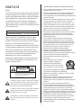
IMPORTANT SAFETY INSTRUCTIONS
1.
Danger
Exposure to extremely high noise levels may cause a
permanent hearing loss. Individuals vary considerably to
noise induced hearing loss but nearly everyone will lose
some hearing if exposed to sufficiently intense noise for a
sufficient time.
2.
3.
4.
5.
The U.S. Government's Occupational Safety and Health
Administration (OSHA) has specified the following
permissible noise level exposures:
DURATION PER DAY (HOURS)
SOUND LEVEL (dB)
6.
7.
8 6 4 3 2 1
90 93 95 97 100 103
8.
According to OSHA, any exposure in the above permissible
limits could result in some hearing loss. Ear plugs or
protectors in the ear canal or over the ears must be worn
when operating this amplification system in order to prevent
a permanent hearing loss. If exposure in excess of the limits
as put forth above, to insure against potentially harmful
exposure to high sound pressure levels, it is recommended
that all persons exposed to equipment capable of inducing
high sound pressure levels, such as this amplification
system, be protected by hearing protectors while this unit is
in operation.
9.
10.
11 .
12.
CAUTION
RISK OF ELECTRIC SHOCK
DO NOT OPEN
CAUTION: TO REDUCE THE RISK OF ELECTRIC SHOCK, DO
NOT REMOVE CHASSIS. NO USER-SERVICEABLE
PARTS INSIDE. REFER SERVICING TO QUALIFIED
SERVICE PERSONNEL.
Read all safety and operating instructions before using this
product.
All safety and operating instructions should be kept for
future reference.
Read and understand all warnings listed on the operating
instructions.
Follow all operating instructions to operate this product.
This product should not be used near water, i.e. Bathtub,
sink,swimming pool, wet basement, etc.
Only use dry cloth to clean this product.
Do not block any ventilation openings, It should not be
placed flat against a wall or placed in a built-in enclosure
that will impede the flow of cooling air.
Do not install this product near any heat sources ;such
as,radiators, heat registers, stove or other apparatus
(including heat producing amplifiers) that produce heat.
Do not defeat the safety purpose of the polarized or
grounding-type plug. A polarized plug has two blades with
one wider than the 0ther.A grounding-type plug has two
blades and a third grounding prong. The wide blade or the
third prong are provided for your safety If the provided plug
does not fit into your outlet, consult an electrician for
replacement of the obsolete outlet.
Protect the power cord being walked on or pinched,
particularly at Plugs, convenience receptacles and the point
where they exit from the apparatus. Do not break the ground
pin of the power supply cord.
Only use attachments specified by the manufacturer.
Use only with the cart, stand, tripod, bracket,
or table specified by the manufacturer or
sold with the apparatus. When a cart is
used, use caution when moving cart/
apparatus combination to avoid injury
from tip-over.
Unplug this apparatus during lightning storms or when
unused for long periods of time.
Care should be taken so that objects do not fall and liquids
are not spilled into the unit through the ventilation ports or
any other openings.
Refer all servicing to qualified service personnel. Servicing
is required when the apparatus has been damaged in any
way; such as, power-supply cord or plug is damaged, liquid
has been spilled or objects have fallen into the apparatus,
the apparatus has been exposed to rain or moisture, does
not operate normally or has been dropped.
WARNING: To reduce the risk of fire or electric shock, do not
expose this apparatus to rain or moisture.
The MAINS plug or an appliance coupler is used as the
disconnect device, the disconnect device shall remain
readily operable.
S3125A
13.
AVIS: RISQUE DE CHOC ELECTRIQUE-NE PAS OUVRIR.
14.
THIS SYMBOL IS INTENDED TO ALERT THE USER TO THE PRESENCE
OF NON-INSULATED "DANGEROUS VOLTAGE" WITHIN THE
PRODUCT'S ENCLOSURE THAT MAY BE OF SUFFICIENT MAGNITUDE
TO CONSTITUTE A RISK OF ELECTRIC SHOCK TO PERSONS.
15.
THIS SYMBOL IS INTENDED TO ALERT THE USER TO THE PRESENCE
OF IMPORTANT OPERATING AND MAINTENANCE (SERVICING)
INSTRUCTIONS IN THE LITERATURE ACCOMPANYING THE UNIT.
16.
APPARATUS SHALL NOT BE EXPOSED TO DRIPPING OR SPLASHING
AND THAT NO OBJECTS FILLED WITH LIQUIDS, SUCH AS VASES,
SHALL BE PLACED ON THE APPARATUS.
17.
3
FRENCH
IMPORTANTES INSTRUCTIONS DE SECURITE
1. Lire avec attention toutes les recommandations et précautions
d'emploi avant d'utiliser ce produit.
2. Toutes les recommandations et précautions d'emploi doivent
être conservées afin de pouvoir s'y reporter si nécessaire.
3. Lire et comprendre tous les avertissements énumérés dans les
précautions d'emploi.
4. Suivre toutes les précautions d'emploi pour utiliser ce produit.
5. Ce produit ne doit pas être utilisé près d'eau, comme par
exemple baignoires, éviers, piscine, sous-sol humides ... Etc.
6. Utiliser exclusivement un chiffon sec pour nettoyer ce produit.
7. Ne bloquér aucune ouverture de ventilation. Ne pas placer le
produit tout contre un mur ou dans une enceinte fernée, cela
gênerait le flux d'air nécessaire au refroidissement.
8. Ne pas placer le produit près de toute source de chaeur telle
que radiateurs, arrivées d'air chaud, fourneaux ou autres
appareils générant de la chaleur (incluant les amplificateurs
producteurs de chaleur) .
9. Ne pas négliger la sécurité que procure un branchement
polarisé ou avec raccordement à la terre, Un branchement
polarisé comprend deux fiches dont l'une est plus large que
l'autre. Un branchement à la terre comprend deux fiches plus
une troisième reliée à la terre. Si la fiche secteur fournie ne
s'insert pas dans votre prise de courant. consulter un
'électricien afin de remplacer votre prise obsolète.
10. Protéger le cordon d'alimentation de tout écrasement ou
pincement, particulièrement au niveau des fiches, des
réceptacles utilisés et à l'endroit de sortie de l'appareil. Ne pas
casser la fiche de terre du cordon d'alimentation.
11. Utiliser uniquement les accessoires spécifiés par le
constructeur.
12. Utiliser uniquement avec le chariot de
transport, le support, le trépied, la
console ou la table spécifiés par le
constructeur ou vendus avec l'appareil.
Lors de l'utilisation d'un chariot, bouger
avec précaution l'ensemble chariotlappareil
afin d'éviter les dommages d'un renversement.
13. Débrancher cet appareil lors d'orages ou s'il n'est pas utilisé
pendant une longue période.
14. Des précautions doivent être prises afin qu'aucun objet ne
tombe et qu'aucun liquide ne se répande à l'intérieur de
l'appareil par les orifics de ventilation ou n'importe quelle autre
ouverture.
15. Pour toutes interventions techniques s'adresser à un
technicien qualifié.L'intervention technique est nécessaire
lorsque l'appareil a été endommagé de n'importe quelle façon,
comme par exemple si le cordon secteur ou sa fiche sont
détériorés,si du liquide a coulé ou si des objets sont tombés à
l'intérieur de l'apparei1,si l'appareil a été exposé à la pluie ou à
l'humidité, s'il ne fonctionne pas normalement ou s'il est tombé.
16. ATTENTI0N:Pour réduire le risque d'incendie ou de choc
electrique ne pas exposer l'appareil à la pluie ou à l'humidité.
17. La prise Mains, au coupler, est utilisé pour la source
d'alimentation êlectrique. Il est conseillê de garder cette prise
facilement accessible.
Danger
L‘exposition a des niveaux eleves de bruit peut provoquer
une perte permanente de l’audition, Chaque organisme
humain reagit differemment quant a la perte de l’audition,
mais quasiment tout le monde subit une diminution de
I’acuite auditive lors d’une exposition suffisamment
longue au bruit intense. Les autorites competentes en
reglementation de bruit ont defini les expositions tolerees
aux niveaux de bruits:
DURE EN HEURES PAR JOUR
INIVEAU SONORE CONTINU EN dB
8 6 4 3 2 1
90 93 95 97 100 103
Selon les autorites, toute exposition dans les limites
citees ci-dessus,peuvent provoquer certaines pertes
d’audition. Des bouchons ou protections dans l’appareil
auditif ou sur l’oreille doivent etre portes lors de
l’utilisation de ce systeme d’amplification afin de prevenir
le risque de perte permanente de l’audition, Dans le cas
d’expositions superieures aux limites precitees il est
recommande, afin de se premunir contre les expositions
aux pressions acoustiques eIevees potentielIement
dangeureuses, aux personnes exposees aux
equipements capables de delivrer de telles puissances,
tels ce systeme d’amplification en fonctionnement, de
proteger l’appareil auditif.
ATTENTION
RISQUE DE CHOC ELECTRIQUE
NE PAS OUVRIR.
S3125A
ATTENTION: AFIN DE LlMlTER LE RISQUE DE CHOC ELECTRIQUE,
NE PAS ENLEVER LE CHASSIS. NE CONTIENT PAS DE
PIECES POUVANT ETRE REPAREE PAR L’UTILISATEUR.
CONFIER LE SERVICE APRES-VENTE AUX
REPARATEURS AGREES.
CE SYMBOLE A POUR BUT D'AVERTIR L'UTILISATEUR DE LA PRESENCE
DE VOLTAGE DANGEREUX NON-ISOLE A L'INTERIEUR DE CE PRODUIT
QUI PEUT ETRE DE PUISSANCE SUFFISAMMENT IMPORTANTE POUR
PROVOQUER UN CHOC ELECTRIQUE AUX PERSONNES.
CE SYMBOLE A POUR BUT D'AVERTIR L'UTILISATEUR DE LA PRESENCE
D'INSTRUCTIONS D'UTILISATION ET DE MAINTENANCE DANS LES
DOCUMENTS FOURNIS AVEC CE PRODUIT.
AFIN DE REDUIRE LES RISQUÉ D'INCENDIE ET DE DECHARGE
ELECTRIQUE, NE PAS EXPOSER CET APPAREIL A LA PLUIE OU A
L'HUMIDITE.
4
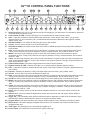
HV™65 CONTROL PANEL FUNCTIONS
2
1
1.)
2.)
3.)
4.)
5.)
6.)
7.)
8.)
9.)
10.)
11.)
12.)
13.)
14.)
15.)
16.)
17.)
18.)
19.)
20.)
21.)
22.)
23.)
24.)
25.)
6
4
3
5
7
10 11
8
9
13
12
16
14
15
23
21
17
18
19
20
22
24
25
Guitar Input Jack - this is a 1/4" 2-conductor input jack for plugging in your instrument. It is intended for guitars but
will accept other instruments as well.
Lead Channel On LED - when this LED light is on, it indicates that the Lead Channel is active.
Gain - adjust this clockwise to increase the amount of distortion. Lower ranges of the control, you get a less
distorted sound. As you increase the gain, you add tremendous amounts of distortion to the signal for a harder
edged "crunch" tone.
Gain Boost Switch - this switch will add more gain to the Lead Channel.
Volume - this is a volume control for the Lead Channel ONLY.
Grind/Punch Switch - this switch selects either the PUNCH or GRIND preamps. Each preamp offers a different
tonal variation.
Bass - this control is the bass control for the Lead Channel. It is passive and set to shelve frequencies at 100Hz.
Turning it fully clockwise, the signal is unaltered. Turning it counterclockwise, the low will be rolled off -12db.
Middle - this control is the midrange control for the for the Lead Channel, and is passive and set to shelve
frequencies at 1KHz. Turning it fully clockwise, the signal is unaltered. Turning it counterclockwise, the low will be
rolled off - 12db.
Treble - this is the high frequency tone control for the Lead Channel. It is passive and set to shelve frequencies at
3KHz on the instrument channel. Turning it fully clockwise, the signal is unaltered. Turning it counterclockwise, the
highs will be rolled off - 12db.
Channel Select Switch - this switch selects between the Lead or Rhythm Channel.
Rhythm Channel On LED - when this LED light is on, it indicates that the Rhythm Channel is active.
Gain - adjust this clockwise to increase the amount of gain of the Rhythm Channel. The gain is applied before the
tone controls.
Fat/Lean - Selecting Fat allows the 12AX7 tube input stage to be over-driven, giving a fatter sound.
Volume - this is a volume control for the Rhythm Channel only.
Bass - this control is the bass control for the Rhythm Channel. It is passive and set to shelve frequencies at 100Hz.
Turning it fully clockwise, the signal is unaltered. Turning it counterclockwise, the low will be rolled off -12db.
Overdrive - this increases the gain of the second stage of the 12AX7 preamp tube on the Rhythm Channel.
Middle - this control is the midrange control for the Rhythm Channel, and is passive and set to shelve frequencies
at 1KHz. Turning it fully clockwise, the signal is unaltered. Turning it counterclockwise, the low will be rolled off 12db.
Treble - this is the high frequency tone control for the Rhythm Channel. It is passive and set to shelve frequencies
at 3KHz on the instrument channel. Turning it fully clockwise, the signal is unaltered. Turning it counterclockwise,
the highs will be rolled off - 12db.
Boost - this is a master volume for both the Lead and Rhythm Channels. It’s an overall volume control for the
amplifier.
Effects Level - this control adds the digital effects section and mixes it into the main signal. Sixteen different
effects are available.
Toggle Tap - This momentary switch performs different functions, depending on which effect is selected. Page 6
describes each effect in detail and how to enhance its usefulness with this switch.
Program Select - this switch will select any of sixteen different effects. Page 6 describes each effect in detail.
Effects Active - this switch engages the digital effects section. The footswitch over-rides this switch when it's
plugged into the amp.
Jewel Light - this jewel light lets you know that the amplifier is on.
Power Switch - this switch turns on and off the AC power to the amp.
5
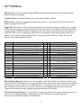
HV™65 Effects
Effects Level this control adds the digital effects section and mixes it into the main signal. Sixteen
different effects are available.
Program Select this switch will select any of the sixteen different effects.
Effects Active this switch engages the digital effects section. The footswitch over-rides this switch
when it's plugged into the amp.
Toggle Tap this switch is a dual function depending on which effects program is selected. On “toggle”
effects, this button pages through alternate variations of the effect. For example, for the Spring Reverb,
it pages through 3 different degrees of brightness. On “tap” effects, this button selects the rate time at
which the effect cycles, by tapping the switch twice. For example, for the Delay setting, it selects the
nd
amount of time between delay repeats (If the 2 tap is beyond the maximum setting, the time will
default to the longest available choice).
Effect Program
Description
Spring Reverb
simulates the spring reverb pan found in vintage tube amps
X
pages through 3 different degrees of reverb brightness
Slap Back
a fast 80ms delay for getting those Rockabilly tones
X
toggles between Slapback and Slapback/Reverb
Chorus
a beautiful thick chorus that can swish with the best of them
X
Delay
an organic sounding delay that has that analog warmth
X
Phaser
Toggle Tap
a sweet and swooshy '70s sounding phaser
Toggle Tap Function
adjusts chorus rate time
adjusts delay time….maximum delay = 680 mS
X
adjusts phaser rate time
Tremolo
a classic sounding tremolo with a hint of vibrato
X
adjusts tremolo rate time
Trem/Reverb
a combination effect of tremolo and room reverb
X
adjusts tremolo rate time
Delay/Reverb
a combination effect of the delay and room reverb
X
adjusts delay time…..maximum delay = 350 mS
Room Reverb
the reverb sound of your amp being played in a room
X
adjusts reverb decay time
Hall Reverb
the reverb sound of your amp being played in a large hall
X
adjusts reverb decay time
Flanger
a deep flanger for getting those spacey sweeping tones
X
adjusts flanger rate time
Rotary
gives you that twirling sound of those fancy old organ cabinets
X
ramps between fast and slow rotary speeds
Octave
shifts the pitch up or down one octave from the original signal
X
toggles between octave up and octave down
Auto Wah
a wah wah that automatically sweeps at your chosen speed
Roto/Reverb
a combination effect of Rotary with room reverb
Chorus/Reverb
a combination effect of chorus and room reverb
X
X
adjusts auto wah rate time
ramps between fast and slow rotary speeds
X
adjusts chorus rate time
Effects Module Memory Aside from all the versatility of the built-in effects, the effects module in your
Kustom amplifier has the ability to store your favorite sounds. All the most recent changes to the Toggle
Tap button are saved in each of the 16 effect locations. For example, If you tap in your favorite delay
time, then go to chorus, and then go back to delay, your own tapped delay time will still be saved.
These setting changes are also retained when powering down the amplifier.
To Restore Factory Settings If you ever want to restore the effects to the factory default settings, you
can do this by selecting Program 1 (Delay/Reverb), then holding the tap switch down and
simultaneously selecting Program 2 (Trem/Reverb).
6
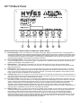
HV™65 Back Panel
1
2
3
4
5
6
7
Jacks located on chassis bottom in sequence shown above
1.)
2.)
3.)
4.)
5.)
6.)
7.)
External Speaker - this is a 2-conductor 1/4" speaker output jack. Rating is 8 ohms minimum. The signal path to
the internal speakers is disconnected when using this jack. Make absolute sure that a 2-conductors speaker cord is
used and it is plugged in to the external speaker cabinet before plugging into this jack. Failure to do so could result
in electrical shock or damage to the amplifier. It is also highly recommended to turn off the AC mains power to the
amplifier before plugging or unplugging any speakers to this jack.
Direct (SPKR Emulated) - this is a 3-conductor. XLR output jack for plugging into Lo-Z microphone inputs as found
on PA or recording mixers. It is intended in place of external mics or used as a built-in direct box. Great effort was
made in emulating the actual speaker sound.
Effects Return - This switching 2-conductor 1/4" line level input jack is the return from an external signal
processor such as a digital delay or EQ. By using this jack, you break the signal path between the preamp output
and power amp input.
Effects Send - this 2-conductor 1/4" line level output jack is the send to an external signal processor. It can also
be used as a preamp output and it does not break the signal path between the power amp and preamp. The front
panel volume and tone controls do affect the output of this jack. The output of the speaker is not emulated, so this
is not a good choice as a substitute for mic-ing the amp.
CD/Tape Input - this is a 3-conductor 1/4" line level input jack. The right and left channels are summed together on
the ring and tip and sent to the preamps master mix section. The boost volume on the front panel is the only control
that has any affect on this input. It acts as a master volume.
Ext Tap FT Switch - this 2-conductor 1/4" switching jack replaces the Toggle Tap switch on the top panel. This is a
nice feature to have, because it allows you to change the selected effect parameter in real time with your foot while
playing. Using the jack disables the top panel switch. The jack accepts a non-LED single button momentary footswitch. This foot-switch is not included with the amplifier. Kustom model KACFS-101M can be purchased
separately. Most keyboard sustain pedals are this type and can also be used. NOTE: most single button foot
switches used on analog instrument amplifiers are alternate contact (the "push on/push off" type). Using this type of
switch will give unsatisfactory results but will not damage the amplifier.
Main FT Switch - this 1/4" stereo jack connects a foot-switch to the amplifier. It uses a special circuit to decode the
3 switches through a simple stereo cable. The tip selects the rhythm or lead channel. The ring is multifunction for
the overdrive on/off switch and the effects active/off switch. This foot-switch is not included with the amplifier.
Kustom model KACFS-301 must be used to enjoy all the features. In an emergency, a mono single-conductor
shielded instrument cable and single button foot-switch can be used to allow switching of the channels only. In this
setup, the LEDs will not be visible, but at least the foot-switch will select Rhythm or Lead channels. The top panel
overdrive on/off and effects active/off switches will still function.
7
HV™65 Extras
dP
OS
Turn a
n
E
N
n to OPE
Tur
ush to CL
1
2
3
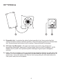
1.) Retractable feet - Located on the cabinet bottom toward the front, there are two feet that
extend downward to allow for tilt back operation. Twist while applying pressure to release these
feet. Once extended, twist further to lock in position. Reverse process for retracting.
2.) AC Power Cord Receptacle - AC power cord can be removed for easy storage and
replacement if damaged. Insert the AC cord (provided) firmly into the AC receptacle. NOTE:
Replace the AC power cord if protective jacket is damaged or ground pin is damaged or
removed.
3.) Fuse - The fuse is located in a fuse tray just below the receptacle. Replace only with same type
and size. For your convenience, a spare fuse is located inside the fuse tray toward the front. To
replace fuse, remove AC power cord. Remove fuse tray by pulling the tab located above the
fuse symbol away from the receptacle.
8
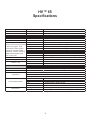
HV™ 65
Specifications
Mode l
Tube s
Output Pow e r
Spe a ke rs
Input Im pe da nce
Hum & Noise
Syste m Ga in
All measurements taken with
1 KHz input signal, Tone
controls flat, Boost volume
control at 0 Unless stated
otherwise, Effects turned off.
Measured at speaker jack
with 8 ohm load.
Nominal Signal to Noise
Effects Loop
Footswitchable Boost
XLR Direct Output
Digital Effects
Footswitch
Power Requirements
Dimensions
HV 65
Preamp
65 W atts, RMS
1 X 12 Inch
Single Input
-60 dBV
Hybrid Tube Guitar Amplifier
1-12AX7
8 Ohms @ 5% THD
Celestion G12P80
100 K ohms
Residual Noise, all level controls 0% (minimum)
45 dBV
65 dBV
50 dBV
70 dBV
10 dBV
10 dBV
6 dBV
27 ~ 37 dBV
Rhythm Channel Nominal gain, Volume @ 5
Rhythm Channel Maximum gain, Volume @ 10
Lead Channel Nominal gain, Volume @ 5
Lead Channel Maximum gain, Volume @ 10
Maximum gain of footswitchable Volume Boost
Gain increase at 1 kHz when Gain Boost is pressed
Gain increase at 1 kHz when Overdrive is pressed
Power amp gain (Effects Return to Speaker, depending on Boost)
70 dBV
0.33 VRMS (-10 dBV)
1 VRMS (0 dBV)
Master Volume Boost
Rhythm Channel, with Volume half and Master Maximum, Boost on 10
Levels w/Boost on 10 to reach full power output
Levels w/Boost on 0 to reach full power output
Adjustable from 0 to +10dB boost AFTER the Effects Loop
After power amp with speaker emulation
24 bit DSP module, 16 effects w/programmable tap-toggle switch.
Use KACFS301 (sold separately) to Select Rhythm/Lead, Boost, Effects On/Off
Uses a standard stereo shielded cable, but can use mono cable for emergency limited functions.
Use KACFS101M (sold separately) or standard momentary Footswitch with mono cable for Tap.
USA/Canada
120VAC/60Hz, 120W nominal
Europe
230VAC/50Hz, 120W nominal
UK
230VAC/50Hz, 120W nominal
Australia
240VAC/50Hz, 120W nominal
Japan
100VAC/50-60Hz, 120W nominal
mm/kg
465 (Height) x 535 (W idth) x 300 (Depth), 16.8kg
Inches/Pounds
18 (Height) x 21 (W idth) x 11 3/4 (Depth), 36.7 lbs
9
TIP
Input
Buffer
Guitar Input Jack
LEAD
GAIN
RHYTHM
FAT/LEAN
GAIN
12AX7
GAIN STAGES
CHANNEL
SELECT
RELAY
TREBLE
MID
LEAD
VOLUME
RHYTHM
VOLUME
LEAD
GRIND/PUNCH
LEAD
TONE STACK
RHYTHM
TONE STACK
BASS
TREBLE
MID
GAIN BOOST
RHYTHM
OVERDRIVE
BASS
10
TAP
FT SWITCH
SLEEVE
TIP
MAIN
FT SWITCH
SLEEVE
RING
TIP
Ring Voltage Sensor
(RVS)
BOOST ACTIVE
BOOST
BOOST VOLUME
EFFECTS ACTIVE
-
-
+
EXTERNAL
SPEAKER
SLEEVE
TIP
CD/TAPE
INPUT
SLEEVE
RING (R)
TIP (L)
DIRECT OUT
(SPKR EMULATED)
+
SPEAKER
EMULATOR
POWER MODULE
EFFECTS
RETURN
SLEEVE
TIP
EFFECTS
SEND
SLEEVE
TIP
SIGNAL FLOW DIAGRAM
TAP
CHANNEL SELECT
Output
Buffer
DIGITAL
EFFECTS
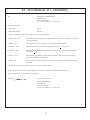
EC Declaration of Conformity
We:
Kustom Musical Amplification Inc.
4940 Delhi Pike
Cincinnati, OH 45238
Tel: 1-513-451-5000 Fax: 1-513-347-2192
Declare that the product
Product name:
Kustom
Product model number:
HV™65
to which this declaration relates is in conformity with the following standards;
EN55013 (A12) : 1995
Limits and methods of measurement of radio disturbance characteristics of broadcast receivers and
associated equipment.
EN55020: 1995
Electromagnetic immunity of broadcast receivers and associated equipment.
EN61000-3-2: 1995
Limits for harmonic current emissions (equipment input current < 16A per phase).
EN61000-3-3: 1995
Limitation of voltage fluctuations and flicker in low voltage supply systems for equipment with
rated currents < 16A.
EN55103-1: 1995
Electromagnetic Compatibility - Product family standard for Audio, Video Audio-visual and
entertainment Lighting Control Apparatus.
EN60065: 1994
Safety requirements for main operated electronic and related apparatus for household and similar
general use.
Following the provisions of EU Council Directive(s): 72/73 EEC and 89/336/EEC.
We the undersigned, hereby declare that the equipment specified above conforms to the aforementioned directive(s).
Name of authorized person: James Brown, Chief Engineer
Signature:______________________
Date: 24 February 2006
Kustom Amplification Inc.
4940 Delhi Pike
Cincinnati, OH 45238
Tel: 1-513-451-5000 Fax: 1-513-347-2192
11
®
Kustom Amplification Inc., 4940 Delhi Pike, Cincinnati, OH • USA
(800) 999-5558 Web: www.kustom.com