1
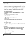
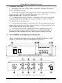
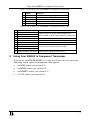
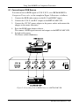
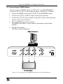
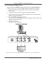
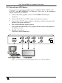
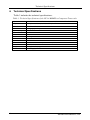
Kramer Electronics, Ltd.
USER MANUAL
Model:
FC-14
RGBHV to Component Transcoder
Contents
Contents
1
2
3
4
5
Introduction
Getting Started
Overview
Your RGBHV to Component Transcoder
Using Your RGBHV to Component Transcoder
Converting an RGB Source
Converting an RGBS Source
Converting an RGBHV Source
Converting a VGA Source
4
5
6
7
6
Technical Specifications
8
5.1
5.2
5.3
5.4
1
1
1
2
3
Figures
Figure 1: FC-14 RGBHV to Component Transcoder
Figure 2: Converting from an RGB Camera to a BETACAM VCR
Figure 3: Converting from an RGBS Workstation to a Plasma Monitor
Figure 4: Converting from a High Resolution Graphics Source to a Plasma Monitor
Figure 5: Converting from a VGA Graphics Source to a Plasma Monitor
2
4
5
6
7
Tables
Table 1: Front Panel FC-14 RGBHV to Component Transcoder
Table 2: Rear Panel FC-14 RGBHV to Component Transcoder
Table 3: Technical Specifications of the FC-14 RGBHV to Component Transcoder
3
3
8
i
Introduction
1
Introduction
Dedication by Kramer Electronics since 1981, to the development and
manufacture of high quality video/audio equipment, makes the Kramer line
an integral part of the finest production and presentation facilities in the world.
In recent years, Kramer has redesigned and upgraded most of the line, making
the best even better! The Kramer line of professional video/audio electronics
is one of the most versatile and complete available, and is a true leader in
terms of quality, workmanship, price/performance ratio and innovation. In
addition to our high quality transcoders, we also offer excellent switchers and
matrices, distribution amplifiers, remote controllers, processors, interfaces
and computer-related products.
Congratulations on purchasing your Kramer FC-14 RGBHV to Component
Transcoder.
This product is ideal for displaying RGB video on:
Plasma monitors
Other display devices equipped with component video inputs
The package includes the following items:
FC-14 RGBHV to Component Transcoder
Power supply
This user manual and the Kramer concise product catalog/CD
2
Getting Started
We recommend that you:
Unpack the equipment carefully and save the original box and packaging
materials for possible future shipment
Review the contents of this user manual
3
Overview
The high quality Kramer FC-14 RGBHV to Component Transcoder is an
adjustment-free, multi-standard converter that converts RGB video to
component video (Y, B-Y, R-Y, sometimes called YUV or Y, Pb, Pr).
The FC-14 supports different sync variants on the RGB inputs:
Separate H & V (RGBHV)
Separate composite sync (RGBS)
Sync-on-green (RGsB)
Sync-on-all (RsGsBs)
1
Your RGBHV to Component Transcoder
In addition, the FC-14:
Recognizes any sync polarity and is compatible with both video level
(0.3V) and TTL level syncs
Transcodes any RGB video (progressive scan or interlaced) to component
format, making it ideal for standard definition video as well as for
high-definition video (VGA, SVGA and XGA)
Uses high quality analog circuitry – eliminating the artifacts associated
with digitizing and allowing the unit to operate with any video resolution!
To achieve the best performance:
Connect only good quality connection cables, thus avoiding interference,
deterioration in signal quality due to poor matching, and elevated noise levels
(often associated with low quality cables)
Avoid interference from neighboring electrical appliances that may
adversely influence signal quality and position your Kramer FC-14 in a
location free from moisture and away from excessive sunlight and dust
4
Your RGBHV to Component Transcoder
Figure 1 illustrates the front and rear panels of the FC-14. Tables 1 and 2
define the front and rear panels of the FC-14, respectively.
Figure 1: FC-14 RGBHV to Component Transcoder
2
KRAMER ELECTRONICS, LTD.
Using Your RGBHV to Component Transcoder
Table 1: Front Panel FC-14 RGBHV to Component Transcoder
#
Feature
Function
1
2
3
4
5
POWER Switch
RGBHV Button
RGBS Button
RGsB Button
RsGsBs Button
Illuminated switch supplying power to the unit
Selects RGBHV as the input format
Selects RGBS as the input format
Selects RGsB as the input format
Selects RsGsBs as the input format
Table 2: Rear Panel FC-14 RGBHV to Component Transcoder
5
#
Feature
Function
1
2
3
4
5
6
7
8
9
10
R IN BNC Connector
G IN BNC Connector
B IN BNC Connector
H/S IN BNC Connector
12V DC
V IN BNC Connector
R-Y OUT BNC Connector
B-Y OUT BNC Connector
Y OUT BNC Connector
RGBHV IN DB15F Connector
Connects to the component video source when selecting
RGB/S or YUV as the input. Automatically detects
whether RGBS or RGsB is input when in the RGB mode
Connects to the horizontal sync input
Power Connector
VDC, 80mA
Connects to the vertical sync input
Connects to the component video acceptor
Connects to the component video source
Using Your RGBHV to Component Transcoder
You can use your FC-14 RGBHV to Component Transcoder to convert the
following source signals to component video signals:
An RGB source (see section 5.1)
An RGBS source (see section 5.2)
An RGBHV source (see section 5.3)
A VGA source (see section 5.4)
3
Using Your RGBHV to Component Transcoder
5.1 Converting an RGB Source
You can convert an RGB signal to Y, B-Y, R-Y, via a FC-14 RGBHV to
Component Transcoder, as the example in Figure 2 illustrates, as follows:
1.
Connect the RGB video camera to the R, G and B BNC inputs.
2.
Connect the Y, B-Y, and R-Y outputs to the BETACAM VCR.
3.
Connect the 12V DC power adapter to the power socket and connect the
adapter to the mains electricity.
4.
Press the RGsB input format selector.
The camera’s RGB signal converts and outputs to the BETACAM VCR.
5.
Switch on the power.
The Power switch illuminates.
Figure 2: Converting from an RGB Camera to a BETACAM VCR
4
KRAMER ELECTRONICS, LTD.
Using Your RGBHV to Component Transcoder
5.2 Converting an RGBS Source
You can convert an RGBS signal to Y, B-Y, R-Y, via a FC-14 RGBHV to
Component Transcoder, as the example in Figure 3 illustrates, as follows:
1.
Connect the RGBS workstation to the R, G, B and H/S BNC inputs.
2.
Connect the Y, B-Y, and R-Y outputs to the plasma monitor.
3.
Connect the 12V DC power adapter to the power socket and connect the
adapter to the mains electricity.
4.
Press the RGBS input format selector.
The RGBS workstation’s signal converts and outputs to the plasma
monitor.
5.
Switch on the power.
The Power switch illuminates.
Figure 3: Converting from an RGBS Workstation to a Plasma Monitor
5
Using Your RGBHV to Component Transcoder
5.3 Converting an RGBHV Source
You can convert an RGBHV signal to Y, B-Y, R-Y, via a FC-14 RGBHV to
Component Transcoder, as the example in Figure 4 illustrates, as follows:
1.
Connect the high resolution graphics source to the R, G, B, H/S and V
BNC inputs.
2.
Connect the Y, B-Y, and R-Y outputs to the plasma monitor.
3.
Connect the 12V DC power adapter to the power socket and connect the
adapter to the mains electricity.
4.
Press the RGBHV input format selector.
The signal from the RGBHV high resolution graphics source converts and
outputs to the plasma monitor.
5.
Switch on the power.
The Power switch illuminates.
Figure 4: Converting from a High Resolution Graphics Source to a Plasma Monitor
6
KRAMER ELECTRONICS, LTD.
Using Your RGBHV to Component Transcoder
5.4 Converting a VGA Source
You can convert and output a VGA signal (or SVGA, XGA, UXGA) to Y,
B-Y, R-Y, via a FC-14 RGBHV to Component Transcoder, as the example in
Figure 5 illustrates, as follows:
1.
Connect the VGA graphics source to the RGBHV DB15F input
connector.
2.
Connect the Y, B-Y, and R-Y outputs to the plasma monitor.
3.
Connect the 12V DC power adapter to the power socket and connect the
adapter to the mains electricity.
4.
Press the RGsB input format selector.
The signal from the RGsB VGA graphics source converts and outputs to
the plasma monitor.
5.
Switch on the power.
The Power switch illuminates.
Figure 5: Converting from a VGA Graphics Source to a Plasma Monitor
7
Technical Specifications
6
Technical Specifications
Table 3 includes the technical specifications:
Table 3: Technical Specifications of the FC-14 RGBHV to Component Transcoder
Inputs:
Outputs:
Video Bandwidth:
Max. Video Level:
Non Linearity:
Video S/N:
Differential Gain:
Differential Phase:
K-Factor:
Control:
Dimensions:
Power Source:
Weight:
Accessories:
8
R, G, B, H/S and V on BNC connectors; RGBHV IN on a DB15F connector
1 component video - (Y, B-Y, and R-Y) on BNC connectors
120 MHz -3dB
1.5 Vpp @ green input
0.3%
60 dB
0.1%
0.4 Deg
<0.05%
4 selector buttons
22cm x 18cm x 4.5cm (8.6" x 7" x 1.8") W, D, H.
12 VDC, 80mA
1.2 kg. (2.65 lbs.) approx.
Power supply
KRAMER ELECTRONICS, LTD.
LIMITED WARRANTY
Kramer Electronics (hereafter Kramer) warrants this product free from defects in material and workmanship under the
following terms.
HOW LONG IS THE WARRANTY
Labor and parts are warranted for three years from the date of the first customer purchase.
WHO IS PROTECTED?
Only the first purchase customer may enforce this warranty.
WHAT IS COVERED AND WHAT IS NOT COVERED
Except as below, this warranty covers all defects in material or workmanship in this product. The following are not covered
by the warranty:
1.
2.
3.
Any product which is not distributed by Kramer, or which is not purchased from an authorized Kramer dealer. If you are
uncertain as to whether a dealer is authorized, please contact Kramer at one of the agents listed in the web site
www.kramerelectronics.com.
Any product, on which the serial number has been defaced, modified or removed.
Damage, deterioration or malfunction resulting from:
i)
Accident, misuse, abuse, neglect, fire, water, lightning or other acts of nature
ii)
Product modification, or failure to follow instructions supplied with the product
iii)
Repair or attempted repair by anyone not authorized by Kramer
iv)
Any shipment of the product (claims must be presented to the carrier)
v)
Removal or installation of the product
vi)
Any other cause, which does not relate to a product defect
vii)
Cartons, equipment enclosures, cables or accessories used in conjunction with the product
WHAT WE WILL PAY FOR AND WHAT WE WILL NOT PAY FOR
We will pay labor and material expenses for covered items. We will not pay for the following:
1.
2.
3.
Removal or installations charges.
Costs of initial technical adjustments (set-up), including adjustment of user controls or programming. These costs are the
responsibility of the Kramer dealer from whom the product was purchased.
Shipping charges.
HOW YOU CAN GET WARRANTY SERVICE
1.
2.
3.
To obtain service on you product, you must take or ship it prepaid to any authorized Kramer service center.
Whenever warranty service is required, the original dated invoice (or a copy) must be presented as proof of warranty coverage,
and should be included in any shipment of the product. Please also include in any mailing a contact name, company, address, and
a description of the problem(s).
For the name of the nearest Kramer authorized service center, consult your authorized dealer.
LIMITATION OF IMPLIED WARRANTIES
All implied warranties, including warranties of merchantability and fitness for a particular purpose, are limited in duration to
the length of this warranty.
EXCLUSION OF DAMAGES
The liability of Kramer for any effective products is limited to the repair or replacement of the product at our option. Kramer
shall not be liable for:
1.
2.
Damage to other property caused by defects in this product, damages based upon inconvenience, loss of use of the product, loss
of time, commercial loss; or:
Any other damages, whether incidental, consequential or otherwise. Some countries may not allow limitations on how long an
implied warranty lasts and/or do not allow the exclusion or limitation of incidental or consequential damages, so the above
limitations and exclusions may not apply to you.
This warranty gives you specific legal rights, and you may also have other rights, which vary from place to place.
NOTE: All products returned to Kramer for service must have prior approval. This may be obtained from your dealer.
This equipment has been tested to determine compliance with the requirements of:
EN-50081:
"Electromagnetic compatibility (EMC);
generic emission standard.
Part 1: Residential, commercial and light industry"
EN-50082:
"Electromagnetic compatibility (EMC) generic immunity standard.
Part 1: Residential, commercial and light industry environment".
CFR-47:
FCC Rules and Regulations:
Part 15: “Radio frequency devices
Subpart B – Unintentional radiators”
CAUTION!
Servicing the machines can only be done by an authorized Kramer technician. Any user who makes changes or modifications to
the unit without the expressed approval of the manufacturer will void user authority to operate the equipment.
Use the supplied DC power supply to feed power to the machine.
Please use recommended interconnection cables to connect the machine to other components.
9
For the latest information on our products and a list of Kramer
distributors, visit our Web site: www.kramerelectronics.com.
Updates to this user manual may be found at
http://www.kramerelectronics.com/manuals.html.
We welcome your questions, comments and feedback.
Kramer Electronics, Ltd.
Web site: www.kramerelectronics.com
E-mail: [email protected]
P/N: 2900-004017 REV 2