1
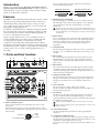
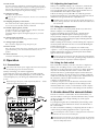
Owner’s Manual
KORG INC.
© 2004 KORG INC.
4015-2 Yanokuchi, Inagi-city, Tokyo 206-0812 Japan
1508 CTH Printed in Japan
Precautions
Location
Using the unit in the following locations can result in a malfunction.
• In direct sunlight
• Locations of extreme temperature or humidity
• Excessively dusty or dirty locations
• Locations of excessive vibration
• Close to magnetic fields
Power supply
Please connect the designated AC/AC power supply to an AC outlet of
the correct voltage. Do not connect it to an AC outlet of voltage other
than that for which your unit is intended.
Interference with other electrical devices
Radios and televisions placed nearby may experience reception
interference. Operate this unit at a suitable distance from radios and
televisions.
Handling
To avoid breakage, do not apply excessive force to the switches or
controls.
Care
If the exterior becomes dirty, wipe it with a clean, dry cloth. Do not use
liquid cleaners such as benzene or thinner, or cleaning compounds or
flammable polishes.
Keep this manual
THE FCC REGULATION WARNING (for U.S.A.)
This equipment has been tested and found to comply with the limits
for a Class B digital device, pursuant to Part 15 of the FCC Rules.
These limits are designed to provide reasonable protection against
harmful interference in a residential installation. This equipment
generates, uses, and can radiate radio frequency energy and, if not
installed and used in accordance with the instructions, may cause
harmful interference to radio communications. However, there is no
guarantee that interference will not occur in a particular installation. If
this equipment does cause harmful interference to radio or television
reception, which can be determined by turning the equipment off and
on, the user is encouraged to try to correct the interference by one or
more of the following measures:
• Reorient or relocate the receiving antenna.
• Increase the separation between the equipment and receiver.
• Connect the equipment into an outlet on a circuit different from that
to which the receiver is connected.
• Consult the dealer or an experienced radio/TV technician for help.
• Unauthorized changes or modification to this system can void the
user's authority to operate this equipment.
CE mark for European Harmonized Standards
CE mark which is attached to our company’s products of AC mains
operated apparatus until December 31, 1996 means it conforms to
EMC Directive (89/336/EEC) and CE mark Directive (93/68/EEC).
And, CE mark which is attached after January 1, 1997 means it
conforms to EMC Directive (89/336/EEC), CE mark Directive (93/68/
EEC) and Low Voltage Directive (73/23/EEC).
Also, CE mark which is attached to our company’s products of Battery
operated apparatus means it conforms to EMC Directive (89/336/
EEC) and CE mark Directive (93/68/EEC).
After reading this manual, please keep it for later reference.
Keeping foreign matter out of your equipment
Never set any container with liquid in it near this equipment. If liquid gets
into the equipment, it could cause a breakdown, fire, or electrical shock.
Be careful not to let metal objects get into the equipment. If something
does slip into the equipment, unplug the AC/AC power supply from the
wall outlet. Then contact your nearest Korg dealer or the store where the
equipment was purchased.
IMPORTANT NOTICE TO CONSUMERS
This product has been manufactured according to strict specifications
and voltage requirements that are applicable in the country in which it
is intended that this product should be used. If you have purchased
this product via the internet, through mail order, and/or via a telephone sale, you must verify that this product is intended to be used in
the country in which you reside.
WARNING: Use of this product in any country other than that for
which it is intended could be dangerous and could invalidate the
manufacturer’s or distributor’s warranty.
Please also retain your receipt as proof of purchase otherwise your
product may be disqualified from the manufacturer’s or distributor’s
warranty.
Specifications
Input connectors:
XLR-3-31 type (+48 V phantom power, switchable),
1/4” TRS phone jack (balanced / unbalanced is Hi-Z)
4 k (XLR-3-31), 10 k (TRS phone Jacks),
1 M (TRS phone Jacks is Hi-Z)
Input impedance:
–48 dBu to 0 dBu @ TRIM=max. — min PAD OFF
–22 dBu to +26 dBu @ TRIM=max. — min PAD ON
Maximum level:
Connectors: ................... XLR-3-32 type, 1/4” TRS phone jack (balanced)
Output impedance: ................................................................................. 150
–60 dBu to –12 dBu @ TRIM=max. — min PAD OFF
–34 dBu to +14 dBu @ TRIM=max. — min PAD ON
Nominal level:
Analog output
Hi-Z
– 48 dBu to 0 dBu @ TRIM=max. — min PAD OFF
– 22 dBu to +12 dBu @ TRIM=max. — min PAD ON
Source impedance: ..................................................................................... 600
Vacuum tubes used: ................................................................................. 12AX7
Compression method: Vacuum tube compression using a photocoupler
Principal specifications
Nominal level: ....................................................................................... +4 dBu
Maximum level: .................................................................................. +16 dBu
Source impedance: ................................................................ 10k or higher
Digital output
Connectors: .............................................................................. optical, coaxial
Format: ....................................... 24bit S/P DIF (IEC60958 / EIAJ CP-1201)
General
Power supply: .......................................... Included AC/AC power supply
Dimensions:
224(W) x 170(D) x 88(H)mm / 8.82”(W) x 6.69”(D) x 3.46”(H)
(including protrusions)
Weight: ................................................................................. 1.33 kg / 2.93 lbs
Frequency response:
10 Hz - 44 kHz ±1 dB @ output +4 dBu, 10 k load
S/N: ............................................................................................. 85 dB (typical)
Included items
AC/AC power supply, Owner’s manual
A/D conversion: ............................................. 24-bit 64 times oversampling
Sampling frequency: ............................................. 44.1kHz, 48kHz, 96kHz
Block diagram
TP-2 [ Tube Preamp ]
INPUT
1
PHANTOM
+48V
GAIN
TRIM
LEVEL METER
SAMPLING
FREQUENCY
44 48 96
S/PDIF OUT
GR
HI-Z
PAD
HA
TUBE
LOWCUT
AD
PHASE
S/P DIF
TRANSMIT
COMP
SENS
OUTPUT
LEVEL
OUTPUT 1
OUTPUT
LEVEL
OUTPUT 2
LINK
INPUT
2
PHANTOM
+48V
GAIN
TRIM
LEVEL METER
GR
HI-Z
PAD
HA
LOWCUT
TUBE
PHASE
COMP
SENS
AD
If you are using a guitar or the line output from an instrument,
connect it to the TRS phone jack.
Introduction
Thank you for purchasing the Korg TP-2 Dual Tube Preamp w/
Optical Compression and Digital Output. In order to enjoy long
and trouble-free use, please read this owner’s manual carefully,
and use your TP-2 only as directed.
Balanced phone plug
GND COLD HOT
Unbalanced phone plug
GND HOT
Features
The TP-2 is a dual-channel preamp featuring two 12AX7 vacuum
tubes, plus fast operating and transparent optical compression
and limiting circuitry. Designed to accept a variety of sources
over a wide range of levels, it is ideal for your most critical and
demanding recording applications.
In addition to both XLR and 1/4” TRS balanced outputs, the TP2 also features both optical and coaxial digital outputs (S/P DIF
format) allowing it to interface with other digital equipment, or
to serve as a stand alone AD converter.
Using a specially tuned version of our acclaimed Valve Force
circuit, the TP-2 delivers the robust, musical warmth and midlow region presence typical of vacuum tubes. The optical
compression responds quickly and transparently, providing a
distinctly full analog body without adversely coloring the sound.
In addition, the optical compressor’s gain reduction and limiting
circuitry allow you to avoid any audio clipping while you’re
recording.
1. Parts and their function
15
14
16
17
2. Phantom power switch/LED
This switch supplies +48V phantom power to condenser mics. The
LED will light if +48V power is being supplied. Power is supplied
only to the XLR jack. Turn this off (LED dark) if you’re using a
dynamic mic.
If a condenser mic is connected or disconnected with the phantom power
switch on, damage to your equipment may occur. For this reason, always
turn the phantom power switch off before connecting or disconnecting a
condenser mic.
3. Phase switch
If you are inputting a stereo source from audio equipment in which
the hot and cold pins are wired in reverse, the stereo image may be
unsteady or cancellation may occur. By pressing this switch in,
you can invert the phase of the input signal by 180 degrees to
compensate.
4. Gain trim knob
This knob adjusts the input gain. If the PAD switch is on (pushed in),
the range is +14 – –34 dBu. If the PAD switch is off, the range is –12 –
–60 dBu.
5. Hi-Z switch
18
19
This switch changes the impedance level of the TRS phone jack to
high impedance. It is on when the switch is pushed in. Turn this
switch on when connecting a high output impedance device such as
guitar or bass.
6. PAD switch
This switch lowers the level of the input signal by 26 dB. The pad is
on when the switch is pushed in. When a line level input source is
connected, turning the pad on will allow the gain trim knob to have a
wider useful range of adjustment.
7. Compressor mode switch
This switch changes the compressor’s response speed. Use the Fast
setting for short sounds such as drums or percussion, and the Slow
setting (press the switch in) for more sustained sounds, such as
vocals.
1
2
3
8. Low cut switch
4
5
6
This switch activates a 70 Hz –6 dB/oct low cut filter.
Use this to reduce unwanted low-frequency content. The filter is on
when the switch is pressed in.
7
8 9
9. Level meter
10 11 12
13
Place the unit horizontally so that the level meters operate correctly.
1. INPUT 1, INPUT 2 jacks
These are balanced inputs that combine XLR jacks and 1/4” TRS
phone jacks.
Unbalanced phone plugs may also be connected to the 1/4” jacks.
If you are using a condenser mic requiring phantom power, connect it
to the XLR jack.
XLR jack
1/4" TRS phone jack
The meter shows the audio level. If the needle moves into the red
area above 0 dB, this indicates that digital clipping is occurring.
Set the gain trim knob and the compressor sensitivity knob to prevent
the needle from exceeding 0 dB.
2: HOT
1: GND
3: COLD
The level meters indicate the level of the signal before it is sent to the
output level faders.
10. Gain reduction LED
This LED will light when gain reduction is being applied by the
compressor.
11. Compressor sensitivity knob
This specifies the audio level where the compressor begins to kick in.
Turning the knob toward the right will increase the sensitivity, so that
compression will be applied even at low levels.
If you don’t want to apply compression, turn this knob all the way to
the left.
12. Link switch
2-2. Adjusting the input level
Press this switch in to link the two channels together for use with
stereo sources. When linked, compression will be applied equally to
both channels whenever either channel exceeds the compressor’s
sensitivity threshold, preserving the stereo imaging.
13. Output level fader
This adjusts the output level.
When the fader is at the 0 dB position, the meter level will match the
output level.
14. Sampling frequency select switch
This switch selects the sampling frequency of the S/P DIF output.
You can choose from 44.1 kHz, 48 kHz, and 96 kHz.
When you’ve finished making your connections, watch the TP2’s level meter while you use the gain trim knob to adjust the
level. Set the trim knob so that the level meter needle does not
exceed 0 dB when the loudest sound is input.
If the level meter goes beyond 0 dB even when the gain trim
knob is turned all the way toward the left, press the PAD switch
and then use the gain trim knob to adjust the level.
Normally if the needle goes beyond 0 dB, digital clipping has occurred, causing distortion. You should set the level so that it does
not exceed 0 dB.
2-3. Using the compressor
15. S/P DIF output (optical, coaxial)
An optical jack and a coaxial jack (IEC 60958, EIAJ CP-1201) both
provide a S/P DIF format digital output.
Connect the digital output to the digital input jack of your other
equipment.
16. Analog output jack (XLR)
This is a balanced output jack using an XLR connector.
17. Analog output jack (TRS)
This is a balance output jack using a TRS phone jack.
18. Power switch
This is the power switch. Press it in to turn the power on. Pressing it
again will turn the power off and return the switch to the out
position.
19. AC9V connector
Turn the compressor sensitivity knob all the way to the left so
that the compressor is not being applied.
Use the gain trim knob to raise the level so that the meter
slightly exceeds 0 dB during the loudest input passages.
Slowly turn the compressor sensitivity knob toward the right.
The gain reduction LED will begin to light, indicating that the
compressor is being applied.
While watching the level meter, continue turning the compressor
sensitivity knob until the level does not exceed 0 dB during the
loudest input passages.
If you want to apply a lot of compression to intentionally
“squash” a vocal, use the gain trim knob to raise the input level
further, and turn the compressor sensitivity knob toward the
right to increase the compression.
By using the gain trim knob to raise the preamp level appropriately,
you can saturate the vacuum tube, generating analog overtones to
enrich the sound in conjunction with the compressor.
Connect the included AC/AC power supply here.
2. Operation
2-4. Using the link switch
2-1. Connections
First connect the AC/AC power supply to the TP-2’s AC9V connector, and then plug it into an electrical outlet.
Start by connecting your external equipment.
Connect the AC/AC power supply. If you will be using the
digital output, set the sampling frequency select switch to the
correct frequency for your other gear, and then turn on the
power.
Before turning on the power, set the output level faders to – so that
sudden loud noise does not occur.
Guitar
Turn on the link switch if you want to use stereo compression.
When you’re recording a stereo source, and the level of one
channel rises to the point where compression is being applied to
only that one channel, then the relative volume of the other
channel will increase, producing the impression that the stereo
image has shifted to one side. In such cases, turning on the link
switch will automatically apply compression to both channels at
the same time, whenever either channel reaches the
compressor’s threshold level.
So that the compressors for both channels will function in the
same way, select the same compressor mode setting for both
channels (either Fast or Slow). You should also set the compressor sensitivity knob to about the same setting for both channels.
3. A note about the vacuum tubes
to digital
input devices to a mixer
or HDR
to the
AC outlet
Mic
This device contains vacuum tubes. We recommend that you
allow the tubes to warm up for about ten minutes after you turn
on the power, before you begin running any audio signals
through the TP-2.
If you begin using this device immediately after turning on the
power, this may cause malfunctions and/or shorten the life of
the vacuum tubes.
In order to maximize reliability, avoid placing this device above
or below heat-producing equipment such as a power amp.
Do not attempt to remove, replace or change the tubes in the TP-2.
The tubes are not a user serviceable part.
Vacuum tubes generate heat. Do not allow your skin to contact the
vacuum tube cover for an extended period of time. Doing so can
cause low-temperature burns.