1
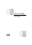
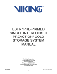
NovaJet 750 Printer Training Guide Ink Installation Printer Calibrations Routine Maintenance Preventive Maintenance Cartridge Checklist Advanced Troubleshooting Print Server Networking NJ750 Training Guide A. Ink Installation 1. ‘Plug and Play Cartridge’ characteristics Installed needle assembly Do not break connection when installing new cartridge 25 ml inside - preprimed 2. Installing ink into reservoirs It is suggested to fill reservoirs over a table to prevent spills on printer; fill to a maximum of 400 ml (50 ml minimum). 3. Attach septum fitting to valve body. Prime line (and cartridge if necessary). NOTE: When the valve body is raised to the up position ink flow is cut off, when the valve body (latch) is closed then the ink line is open. 2 NJ750 Training Guide a) Prime line using the short needles (purple in color); attach short needle to each of the 4 valves. Connect septum needle to EasyPrime by inserting into female receiver. Depress and hold EasyPrime activation button to provide a solid burst, wait 20 seconds, or until ink line is full. b) Lift valve actuator (to up postion) and remove purple septum needle assembly. c) Connect cartridge’s septum needle to valve and close valve – wait 60 seconds then remove the blue tape from cartridge jet plate. NOTE: If attempting to recharge an existing cartridge, then disconnect cartridge from stall position and prime cartridge (print head) using multiple sets of one-second bursts until ink is visible in the ink line. This may take 1-2 minutes to accomplish depending on the prime of entire ink line. Ensure EasyPrime adapter is flush to cartridge jet plate – a siphoning sound (slight sucking) should be heard when priming the cartridge properly. 4. Activate the color test pattern for ink starvation problems. Select: SETUP MENU – PRINT MODE MENU – PRINT PASSES – SELECT 3, OK. Select: UTILITY MENU – SERVICE MENU – DIAGNOSTICS – COLOR TEST MENU – STALL SELECT (or ALL COLORS)– choose color. Select DENSITY SELECT to 100%. Select COLOR TEST PRINT. Verify color bar is printed without ink starvation. Ink Test/Recovery Procedure (Color Test Print) This is a pressure test of the system, so please disregard the two-pass quality. Each pass of the carriage assembly should lay 3 NJ750 Training Guide down a solid band of color with 33% ink load. Color Test Failures: - Example A above depicts complete ink starvation in magenta. This problem may be corrected by using the EasyPrime and establishing the required pressure inside the cartridge. Replace septum connector/needle if repeated attempts continue to fail. - Example B above depicts partial ink starvation in magenta (ink fires at 100% at the beginning of each pass but then starves). This problem can be corrected by ensuring 19 ml of ink is present inside the cartridge (level must be between 8 ml and 35 ml for proper operation – refer to NOTE below). NOTE: To install ink into a cartridge or to verify proper cartridge ink level obtain syringe with tube extension from accessory kit. Pull 20 ml of ink into syringe. Lift cartridge stall position valve to up position to cut off ink flow. Temporarily remove septum connector from cartridge. Install ink into cartridge by depressing syringe plunger; pull back on plunger to remove excess ink (if any). Reconnect septum needle to cartridge and close valve actuator (lower) to restore ink flow to cartridge. The cartridge will need to be primed to restore negative pressure inside cartridge – refer to step 3 above. 5. Activate the Prime pattern. Select UTILITY MENU – PRIME. Verify all colors are printed. Verify no clogs are present in the prime pattern. Manual or automatic jet compensation is provided up to 20 jets in each cartridge. Ensure the integrity of the diagonal lines are consistent and smooth. Clean or replace cartridge if unsatisfactory. 4 NJ750 Training Guide 5 NJ750 Training Guide 6. Cartridge Jet - Manual Bypass Feature Example: to manually bypass a clogged black (K) jet, perform the following steps: Open Jet Menu Main Menu Feed Media Menu Black Edit List Print Jet List Cut Setup Menu Cyan Edit List Clear List Menu Pause Utility Menu Magenta Edit List Load Media Exit Yellow Edit List Reset Black Edit List Utility Menu Access Cartridge Print Settings Paper Axis Next Option Color Calib Menu Service Menu # Prime Display Settings Calibration Menu Open Jet Menu Paper Axis Color Db Menu 1: On Prev Option Exit Calibration Menu Use Calib X/Y Paper Axis Test Toggle Jet Ok Press Next Option until clogged jet number is displayed, press Toggle Jet to turn jet OFF, press OK. Exit Jet manually bypassed, jet good Jet is bad; jet readdressed automatically Jet manually bypassed, jet clogged Jet is clogged (Jet electronics are good though) 6 NJ750 Training Guide B. Printer Calibrations A. Paper Axis Test Prior to running a Paper Axis Test ensure a minimum of 36 inch media is loaded. To activate the Paper Axis Test select Utility Menu - Calibration Menu - Paper Axis Test. An upside-down "T" will be printed in the 33.00 inches center of the media, the media will advance approximately 33 inches or 838 mm and another "T" will be printed. This calibration is extremely important for paneling and framing operations to ensure proper line Distance between the two length accuracy; printer accuracy is “T’s” should be 33.00” +/guaranteed to +/- 0.2%. Cut off and measure 0.05” (inches) the distance between the two T's using a draftsman ruler, enter the true value under under 'Paper Axis'. Select Utility Menu, Calibration Menu, Paper Axis, enter the true value once only. Note: the display will always indicate 33" or 832.2 mm as the zero reference position but the printer is now adjusted for this media type. B. Slow Deadband To activate the Slow Deadband calibration select Utility Menu - Service Menu Calibration Menu - Slow Db Test. The Slow dB Test pattern will print very slowly. This is a mechanical adjustment of the printer servo system and should be performed monthly. Ensure the vertical lines are straight, if out of alignment, as in this example, then an adjustment is necessary. Select Utility Menu, Service Menu, Calibration Menu, Slow Deadband - change the value and rerun the pattern until correct. NOTE: this calibration is normally not required; for CAD operations mainly. C. Color Deadband To activate the Color Deadband calibration select Utility Menu - Calibration Menu - Color dB Menu Color dB Test. The Color dB pattern will print. This is an electronic calibration for compensating the differences in cartridge resistances. Always perform this calibration whenever a cartridge is replaced. To adjust left NJ850 print head (i.e. values 1-4), select Left at control panel. Choose the best value under each aligning set of colors. To adjust the right print head (values Y, M, C, and K) select Right at the control panel. Select the value under the best group of vertical lines in each color. Please do not choose one value to characterize all colors unless illustrated by the pattern. 7 NJ750 Training Guide D. Color Calibration To activate the Color calibration select Utility Menu - Color Calib. Menu – Calib Test (NJ850: Both Vert Calib Test and Horiz. Calib. Test.) Seven horizontal patterns followed by seven vertical patterns will print. The color calibration pattern should be performed whenever a cartridge is removed from the carriage for cleaning or replacement. Choose the best value under each aligning set of colors, i.e. yellow to magenta, then magenta to cyan, then cyan to black. Enter the most correct value for each of the 14 fields. Note: stalls 1 through 4 correspond to the Left 4 cartridges. E. Deadband Check To activate the Deadband calibration select Utility Menu - Service Menu Calibration Menu - Deadband. The deadband pattern will print very quickly in all color ranges. This is a final check of printer calibrations to ensure alignment has been achieved. Ensure the vertical lines are straight with respect to each color, if severely out of alignment, as in this example, then a re-calibration of the printer is necessary or cleaning of the encoder strip is necessary. Note: The pattern does not have to be perfect, just close to maintaining vertical alignments. F. Controlling Image Skew (not media skew as this is mechanical). The NovaJet 750/800 series of printers are designed with self-aligning pinch rollers. The alignment process takes place when media is advancing forward, but not backwards. Loading media is critical to the media alignment and reducing skew. Many times the media is loaded at a slight skew and will take several feet of advancing media to get it aligned properly. This can be improved by following the steps below. 1. Load the media and align the rear media guides. 8 NJ750 Training Guide 2. Advance the media though the printer about 1 foot, using the Feed Media Menu/Forward button. 3. Put the printer media feed in “Sheet” mode (Set-up Menu/Paper Option Menu/Supply Type/Sheet). Using the media “Forward” button, drive the media forward until it is pulled tight. 4. Change the media feed back to “Roll” or “Take-up” (Set-up Menu/Paper Option Menu/Supply Type/ 5. Roll or Take-up). 6. Advance the media forward three feet to check alignment with the white media guideline. 7. Start printing the image. G. ACCEPTABLE IMAGE SKEW: PERFECT REFERENCE RECTANGLE L2 L1 L ACTUAL OUTPUT LW MEDIA PERIMETER EXHIBIT A Assuming the media loading instructions as defined in the user manual have been followed, Exhibit A describes the maximum permissible image skew. The maximum skew is: 0.30% of ∆L = (L1 - L2) – except for NJ880 (no skew specification has been designated) Example: If LW = 59.61 inches (1.51 m.), L = 48.00 inches (1.22 m.) Then: L1 should equal L2 = 76.53 inches (1.94 m.) The actual permissible skew (L1 - L2) = (.003) (76.53) = .229” (5.82 mm.) NOTE: This is the only method used to determine skew. 9 NJ750 Training Guide C. Routine Maintenance 1. Perform routine maintenance at recommended plot time hours and in accordance with prescribed documentation. NOTE: The NovaJet printer must be cleaned and serviced routinely or print output anomalies or printer failures may occur during normal operations. It is strongly suggested to take 15 minutes once a week (i.e. every Monday morning) and perform printer cleaning rather than attempt to remember each cleaning cycle as listed below. INTERVAL COMPONENT CLEANING AGENT 25-50 Hours Platen/External Surfaces NovaKlean solution on Lint-Free Towel Can cause paper sensing errors; resulting in ‘no printing’ symptoms. INTERVAL COMPONENT CLEANING AGENT 10-20 Hours Service Station NovaKlean or Distilled Water 10 NJ750 Training Guide INTERVAL 10-20 Hours COMPONENT Cartridge Jet Area CLEANING AGENT NovaKlean on lint-free Towel 50-75 Hours Encoder Strip NovaKlean on cotton swab, followed by Isopropyl Alcohol on cotton swab (perform every 25 plot hours for GO ink printing) INTERVAL 50-75 Hours INTERVAL 50-75 Hours COMPONENT Trailing Cable COMPONENT Slide Shaft CLEANING AGENT NovaKlean on lint-free Towel CLEANING AGENT NovaKlean on lint-free Towel 11 NJ750 Training Guide INTERVAL 50-75 Hours COMPONENT Flex Driver Cables CLEANING AGENT NovaKlean on lint-free Towel Ensure cables are dry. INTERVAL COMPONENT CLEANING AGENT 20-30 Hours Carriage Bushings NovaKlean on cotton swab 50-75 Hours Cutter Groove Toothpick or small wooden tool INTERVAL 25-50 Hours INTERVAL COMPONENT Pinch/Lower Roller COMPONENT CLEANING AGENT NovaKlean on lint-free Towel CLEANING AGENT 50-75 Hours Platen Vacuum Holes Toothpick or small wooden tool 80-100 Hours Y-Arm Surface NovaKlean on cotton towel 12 NJ750 Training Guide INTERVAL COMPONENT CLEANING AGENT As Required Paper Sensor Isopropyl Alcohol on cotton swab The Paper Sensor is located directly behind the Right Carriage magenta cartridge approximately 4 mm. Spin cotton swab at an upward angle of 30 degrees. 13 NJ750 Training Guide D. Preventive Maintenance Perform preventive maintenance at recommended plot time hours and in accordance with prescribed documentation (authorized service providers only!). At 2000 plot hours replace both Carriage Bushings, Trailing Cable, Service Station and thorough perform cleaning (including carriage paper sensor and encoder sensor). 14 NJ750 Training Guide E. Cartridge Checklist (for warranty replacement) 1. Electrically bad jets (100% filled block) in the Prime pattern (10 nozzle failures for 20 Jet (red-top) cartridges and <500 ml throughput (see UTILITY MENU – SERVICE MENU – CARTRIDGE INFO) warrants a cartridge replacement. Manually bypass clogged jets as necessary (clogged jets, misfires, are not covered by the warranty.) Clean the jet plate thoroughly by blotting with a water dampened lint-free towel to clear clogs. Catastrophic Failure (more than 35 jets) Faulty Power Line; check compensation list to verify photo mode is still supported. Clean rear electrical contacts and reseat cartridge to verify problem is not intermittent. Faulty Address Line; check compensation list to verify photo mode is still supported. Clean rear electrical contacts. Multiple Power and Address line failures; one cartridge is defective (use post-it note technique to isolate defective cartridge.) A clogged jet is illustrated as jet 111; jets 105 and 108 are manually bypassed (80% filled blocks only.) Jet 114 is defective and is automatically being bypassed. Between 20 and 35 jets, in each color, may be defective or bypassed to maintain photo quality printing. 2. Microbanding is typically caused by the low pass modes or improper color deadband and color calibrations. If not, then jet degradation of one color probably exists. Inspect prime pattern for diagonal line integrity and consistency (line should be perfectly straight with no misfires). Faulty K line; shifts up and down randomly Microbanding Example; check pass mode 3. Ink Starvation (caused by the Cartridge and not the Ink Delivery System); defective jet plate seal or top lid seal. Test alternate ink delivery lines and tubing needles before cartridge replacement. Swap cartridge positions to check electrical connectivity. 15 NJ750 Training Guide F. Advanced Troubleshooting 1. Skewing of the output image is normally a dirty or defective encoder strip/sensor. Clean encoder strip thoroughly top and bottom using Windex or NovaKlean solution. Clean encoder sensor by spraying Windex directly onto sensor; blow dry with canned air – refer to NJ1000i Technical Bulletin 5. Replace encoder strip (service required) if problem cannot be corrected. 2. Missing data in an image is typically a print server or network traffic problem. Increase data port rate or reconfigure print server. 3. Multiple lines throughout a print typically indicates a problem with the connectivity to the printer. Ensure only an IEEE compliant parallel printer cable (if used) and/or switchbox are used. One protruding line or an area showing over spray is typically a RIP problem and not necessarily a connectivity issue. 16 NJ750 Training Guide 4. Faint cut lines or heavy lines which angle slightly on one end are caused by the carriage head hitting the media surface. Media up to a 20 mil thickness can pass through the printer. Ensure media has not been exposed to humidity for long periods as this will cause media to become stiff. Check with technical support for media types which can pass through the printer. 5. Printer carriage hesitation. Hesitation of the carriage assembly during printing can be due to various factors; i.e. Slow processor in workstation for Software RIPs, screen saver turned on, improperly configured parallel port for non-networked environments, incorrect speed setting for driver data transfer rate, print server setup (untested print server used/incorrect SEH setup), other network traffic, etc. 6. Horizontal bands which extend the width of the image and repeat at a relatively consistent rate are usually caused by the Autowipe feature being turned on or improper ink pre-heat settings. 17 NJ750 Training Guide 7. Larger than normal ink droplets (0.5- 2 mm) on the media are caused by excessive pressure in the cartridge. Ensure the cartridge only has 20 ml of ink inside and the ink reservoirs do not have more than 400 ml of ink inside. Printer stand surface or floor area must be level and flat. 8. Microbanding is typically caused by incorrect printer calibrations or low pass printing. Print pass mode of 4 or lower may cause banding. Ensure all calibrations are performed correctly. Defective or clogged cartridges may also cause microbanding. Perform printer calibrations and replace associated cartridge (s) to verify. 208 Jet Cartridge 18 NJ750 Training Guide Ensure the diagonal lines in the prime pattern are solid and exhibit consistency. Up to 20 jets may be compensated in each cartridge while maintaining photo pass quality printing. 9. Horizontal bands along the right edge of the media are typically caused by a dirty service station or cartridge. Curling media (from high humidity) or media too thick can also cause the banding problem. 19 NJ750 Training Guide 10. Ink over spray can be caused by compression utilities. Electrostatic discharge from film media has also been known to exceed the printer specifications and cause inconsistent overspray. Verify the strike-plate brushes are in good condition before resuming print operations. Do not use 3-prong to 2-prong adapters when connecting printer to power source; do not provide additional printer grounding other than through printer’s standard power cord. 11. Ink Starvation (occurring from 10 minutes to 4 hours) is typically caused by inadequate cartridge priming or a leak in the ink delivery system. Ensure the cartridge has been properly primed using the NovaPrime or EasyPrime device. Ensure all septum connectors are tightened securely. Refill cartridge to 20 ml of ink and reprime cartridge (establish negative pressure). Replace septum connectors/tubing needles if cracked/broken; replace cartridge. 12. Text errors or lines which appear within the text is usually caused by the application. Delete text box within application and create a new field. Diagonal banding or horizontal lines extending from the text is normally a postscript or RIP error. Check workstation memory (minimum 512 MB) and ensure the RIP workstation has a minimum of 4GB free for processing files. 20 NJ750 Training Guide 13. Vertical banding through an image can be caused by mottling of the ink on low saturation media like bond, the carriage bushings are worn out causing ‘carriage chatter’, or the lower roller is extending too high through the platen. Vertical banding can also be caused by a defective trailing cable or when ink saturations are extremely high (>290%) and the dryer is used with high heat applied. 14. Unusual patterns which print in either the Prime pattern (lower left illustration) or in normal prints (lower right illustration) are symptoms of a defective trailing cable. Replace the white trailing cable (service required). To prevent these failures from occurring ensure the trailing cable is cleaned every two weeks. 21 NJ750 Training Guide 15. For initialization failures first ensure the memory module is properly seated at the Main PWA (remove 5 screws to access) and verify the proper LED states (NJ800 series only): D1 – Normally flashes; DSP is not active. Steady during print operations. D9 – Normally flashes; Power PC processor is idle. Stops flashing when processor is active (i.e. during paper sensing operations). D10 – Normally OFF; Flashes during initialization, then turns off. LED staying on would indicate a problem when the FPGA is unconfigured. Ensures the gate array chips have been properly programmed (one on Main PCB and on each Carriage PCB). D8 - +24V available. D13 - +5V available. Check the Boot Code for proper initialization. While holding down the two buttons indicated below turn on the printer, a cyclical two-beep sequence should be heard. 16. For media feed and takeup system failures first ensure the correct supply mode is enabled (Sheet, Roll, Roll 2, or TakeUp). Check sensor bracket alignment and motor wiring connections to each motor (remove 4 screws to access each motor). 22 NJ750 Training Guide 17. For NJ750 and 800 series dryer system failures ensure the logic cable and power cable are properly secured. Check sensor status for error messages. Cycle power to verify operation. From the top-level menu of the printer, check the dryer sensor status (NJ800 only). Utility Menu Service Menu Diagnostic Menu Accessory Menu Sensor Status The printer LCD will display the following information: Dryer Mode: cccccccc Plenum T. = ## deg. C MBoard T. = ## deg. C MBoard H. = ## pct. RH The Dryer Mode: (cccccccc) indicates the current dryer setting. Operational modes are “OFF”, “ON (Heat), “AUTO”, “FANS ONLY(No-Heat)” or “DISABLED (error condition)”. Plenum T. and MBoard T. (main-board T.) indicate temperature and are displayed in degrees C. MBoard H. (main-board humidity) indicates the ambient relative humidity as a percentage. 23 NJ750 Training Guide G. Print Server Networking (SEH Intercon print server) A. The 100baseTX parallel print device allows connection between a 100 baseTX network environment and the NovaJet 750. The SEH print server draws power directly from the printer’s parallel port. " High speed print server; 1 Mbytes/sec data rate (compliant with IEEE 1284) " " " Powered by parallel port ECP mode support Protocols; IPX/SPX, TCP/IP, WINS, BCP/TBCP, NetBIOS/SMB, IPP, DNS, SLP, SNMP, SMTP, Ethernet/Token Talk Phase 2, HTTP/HTML " Operating Systems; Novell Netware 3.x – 5.x, UNIX, BS2000, Apple MacOS 7.x – 9.x, Microsoft Windows 3.X, 95/98, NT 4.X, 2000, XP " " Easy Installation and Simple Management JetAdmin, WebJetAdmin, and EpsonNet Tools Support B. Depressing the blue test button (located on side of server) sends the currently loaded IP address to printer to be displayed on the printer’s control panel. Received IP Address 192.168.002.010 Ok C. The Status and Link LED’s (green in color) should be steady when the printer has been turned on and a properly configured network connection has been established. The Status LED will blink until the server is configured properly in the proper IP range of the device (could be dependent of the HUB’s or Network Interface Card’s IP range). The Activity LED (amber in color) will only blink while the server receives data from the host computer (typically blinks during printing). D. Print Server 24 NJ750 Training Guide Configuration for Windows 2000/XP Printer Networking is a basically a 3-step Process: 1. Assign TCP/IP address of host computer/server 2. Assign TCP/IP address to print server (may also need to install windows printer port during this process) 3. Assign TCP/IP address to RIP (same as print server) For the most recent software version (i.e. InterCon NetTool) go to the following URL: http://www.seh.de/ NOTE: The most common download, for PC users, from SUPPORT FIRMWARE/SOFTWARE (select IC105 FastPocket-TX) is: Version 1.8.23 for Win 2000, Win XP, Win 9x Administration tool for InterCon print servers. 25 NJ750 Training Guide NOTE: Before you can configure a Windows print queue, you must first configure an IP address on both your PC and the SEH print server. 1. PC PROTOCOL SETUP 1. If you have not already done so, install the TCP/IP protocol on your PC. This is done by first RIGHT-CLICKING on the My Network Places icon on your desktop. Select Properties from the list. The Network dialog box appears. 2. Double click on the Local Area Connection icon. When the Local Area Connection dialog box opens, double click on the TCP/IP protocol to activate the TCP/IP properties. See figure below. 3. Once the TCP/IP properties dialog box is open enter the information as follows: IP Address- 192.168.254.201 SUBNET Mask- 255.255.255.0 DNS Server- 192.168.254.195 26 NJ750 Training Guide Alternate DNS Server- 192.168.254.190 Leave the Gateway blank. See Figure Below. NOTE: To configure the SEH print server you will have to load the InterCon NetTool. Insert the InterCon CD into your CD drive or obtain from: http://www.seh.de/ 2. PRINT SERVER PROTOCOL SETUP Run the CD.EXE from the Autorun folder. Once started press the top button(British Flag). Press the InterCon-NetTool button to install. Follow the prompts and finish the installation. 1. Once loaded activate the InterCon-NetTool. The SEH will Auto-Assign itself an IP address, using DHCP, within the IP range of your PC. To change the IP address and Subnet Mask, double click on the IP address or select Properties from the Edit pull down menu. See figure below. 27 NJ750 Training Guide 2. To assign your IP address and Subnet Mask, choose TCP/IP from the configuration tree on the left. Assign 192.168.254.200 for the IP address. Assign 255.255.255.0 for the Subnet Mask. Leave the Gateway blank or zeros, and de-select DHCP at the bottom. See figure below. 28 NJ750 Training Guide 3. Close the InterCon-NetTool. Your settings will be saved in the print server. You are now ready to setup the Windows Printer Port. 3. WINDOWS PRINTER PORT SETUP NOTE: If RIP software has been previously loaded then a hot folder with an assigned port will have ‘normally’ already been loaded – this step may not be necessary unless the Windows printer port is to be used for printing purposes. This step will be required if the EFPU print utility is to be used for downloading firmware or test files however. 1. 2. 3. 4. Select Start, Settings, Printers. Double click on Add Printer, the Add Printer Wizard dialog box appears. Click Next. Select “Local Printer”. Click Next. At the bottom of the dialog box select “Create a new port”. Change selection to “Standard TCP/IP Port”. Click Next- the TCP/IP Printer Port Wizard will start. Click Next. See figure below. 29 NJ750 Training Guide 5. Under “Printer Name or IP Address” enter 192.168.254.200. The “Port Name” will self generate. Click Next. See figure below. 30 NJ750 Training Guide 6. Under “Device Type” select “Network Print Server (1 Port)” the first one in the list. Click Next, then Finish. See figure below. 7. You will now be prompted for the Manufacture and Printer Type. Select “Generic” and “Generic/ Text Only”. Click Next, Next again, and Next again. Do not share this printer. Click Next. Select no to Print a test Page. Click Next and Finish. Your TCP/IP printer port is now setup. 31 NJ750 Training Guide 4. RASTER IMAGE PROCESSOR (RIP) TCP/IP ASSIGNMENT 1. The last step of the networking setup is to assign an IP address in the RIP software (this TCP/IP address is the same address assigned to the SEH Intercon print server). The location of the ‘device’ or ‘TCP/IP setup’ is normally located under the RIP software ‘setup’ drop-down menu or under the ‘Printer Configuration’ folder, depending on the RIP used. 32