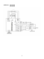
1
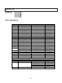
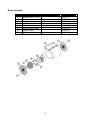
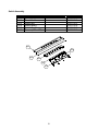
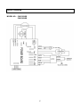
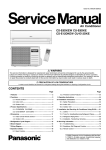
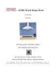
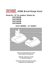
KOBE Brand Range Hood
Model No.:
CH0130SQB (30'')
CH0136SQB (36'')
CH0142SQB (42'')
CH0148SQB (48'')
CH-101 SERIES – 18'' HEIGHT
INSTALLATION INSTRUCTIONS
AND OPERATION MANUAL
- READ AND SAVE THESE INSTRUCTIONS -
CONTENTS
IMPORTANT SAFETY INSTRUCTIONS.........................ERROR! BOOKMARK NOT DEFINED.
COMPONENTS OF PACKAGE ................................................................................................. 3
INSTALLATION ......................................................................................................................... 4
UNDER THE CABINET INSTALLATION .................................................................................6
STAND ALONE INSTALLATION .............................................................................................9
OPERATING INSTRUCTIONS ................................................................................................ 12
MAINTENANCE..............................................................ERROR! BOOKMARK NOT DEFINED.
SPECIFICATIONS ................................................................................................................... 16
MEASUREMENTS & DIAGRAMS............................................................................................ 17
PARTS LIST ............................................................................................................................ 22
CIRCUIT DIAGRAM................................................................................................................. 27
DISCLAIMER ........................................................................................................................... 29
WARRANTY ............................................................................................................................ 30
PRODUCT REGISTRATION.................................................................................................... 32
- READ ALL INSTRUCTIONS CAREFULLY BEFORE STARTING ALL W IRING MUST BE DONE BY A PROFESSIONAL AND IN
ACCORDANCE W ITH NATIONAL AND LOCAL ELECTRICAL CODES.
IMPORTANT SAFETY INSTRUCTIONS
- PLEASE READ THIS SECTION CAREFULLY BEFORE INSTALLATION WARNING:
TO REDUCE THE RISK OF FIRE, ELECTRIC SHOCK OR PERSONAL
INJURY, OBSERVE THE FOLLOWING:
1) Installation and electrical wiring must be done by qualified professionals and in accordance
with all applicable codes and standards, including fire-rated construction.
2) When cutting or drilling into wall or ceiling, be careful not to damage electrical wiring or
other hidden utilities.
3) Ducted fans must be vented to the outside.
a) Before servicing or cleaning unit, open the light panel and SWITCH POWER OFF AT
SERVICE PANEL.
b) Clean grease laden surfaces frequently. To reduce the risk of fire and to disperse air
properly, make sure to vent air outside. DO NOT vent exhaust air into wall spaces,
attics, crawl spaces or garages.
NOTE
WARNING:
-
-
-
This warranty is invalid without an authorized agent’s receipt
or if unit is damaged due to mis use, poor installation,
improper use, mistreat ment, negligence or any other
circums tances beyond the control of KOBE RANG E HOO DS
authorized agents.
An y repair ca rried out without the
supervision of KOBE RANGE HOODS authorized agents will
auto matically void the warranty.
-
KOBE RANG E HOODS will not be held responsible for any
da mages to personal property or real estate or any bodily
injuries whether caused directly or indirectly by the range
hood.
TO REDUCE THE RISK OF PERSONAL INJURY IN THE EVENT OF A
RANGE TOP GREASE FIRE:
Keep all fan, baffle/spacer/filter/oil tunnel/oil container and grease-laden surfaces clean.
Grease should not be allowed to accumulate on fan, baffle/spacer/filter/oil tunnel/oil
container.
Always turn hood ON when cooking at high heat.
Use high settings on cooking range ONLY when necessary.
Do not leave cooking range unattended when cooking.
Always use cookware and utensils appropriate for the type and amount of food prepared.
Use this unit only in the manner intended by the manufacturer.
Before servicing, switch power off at service panel and lock service panel (if possible) to
prevent power from switching on accidentally.
Clean ventilating fan frequently.
1
What to Do In The Event Of a Range Top Grease Fire
•
•
•
•
SMOTHER FLAMES with a close fitting lid, cookie sheet, or metal tray, and then turn off the
burner. KEEP FLAMMABLE OR COMBUSTIBLE MATERIAL AWAY FROM FLAMES. If
the flames do not go out immediately, EVACUATE THE AREA AND CALL THE FIRE
DEPARTMENT or 911.
NEVER PICK UP A BURNING PAN – You May Get Burned.
DO NOT USE WATER, including wet dishcloths or towels – a violent steam blast will result.
Use an extinguisher ONLY if:
a) You have a Class A, B, C extinguisher and know how to operate it.
b) The fire is small and contained in the area where it started.
c) The fire department has been called.
d) You can fight the fire with your back to an exit.
What to Do If You Smell Gas
•
•
•
Extinguish any open flame.
Do not try to turn on the lights or any type of appliance.
Open all doors and windows to disperse the gas. If you still smell gas, call the Gas
Company and Fire Department right away.
CAUTION
1) For general ventilation use only. Do not use to exhaust hazardous or explosive materials
and vapors.
2) To reduce the risk of fire, use only metal ductwork. Sufficient air is needed for proper
combustion and exhausting of gases through the flue (chimney) to prevent back drafting.
3) Follow the heating equipment manufacturer’s guideline and safety standards such as those
published by the National Fire Protection Association (NFPA), and the American Society for
Heating, Refrigeration and Air Conditioning Engineers (ASHRAE), and code authorities.
4) Activating any switch on may cause ignition or an explosion.
5) Due to the size and weight of this hood, two people installation is recommended.
ELECTRICAL SHOCK HAZARD – Can result in serious injury or death.
Disconnect appliance from electric power before servicing.
If
equipped, the fluorescent light bulb contains small amounts of
mercury, which must be recycled or disposed of according to Local,
State, and Federal Codes.
2
COMPONENTS OF PACKAGE
(Must keep all material for returns or refunds)
RANGE HOOD BOX
KOBE Range Hood – 1
Warranty Registration Card –1
Instructions Manual – 1
Baffle Filter
- 2 (30”, 36”, 42”)
- 3 (48”)
Stainless Steel Spacer
- 0 (30”)
- 1 (36”)
- 2 (42”, 48”)
Oil Tunnel – 1
Ducting Transition – 1
Screw Package for Transition – 1
Hood-Mounting Bracket-2
Screw Package for Hood-Mounting Bracket –1
3/16" X 3/8" (8 pc)
DUCT COVER KIT (Sold Separately)
Option Of:
Model No. CH0030DC-12 for 30” hood
KOBE Duct Cover – 1
Screw Package for Duct Cover - 1
Model No. CH0036DC-12 for 36” hood
KOBE Duct Cover – 1
Screw Package for Duct Cover - 1
Model No. CH0042DC-12 for 42” hood
KOBE Duct Cover – 1
Screw Package for Duct Cover - 1
Model No. CH0048DC-12 for 48” hood
KOBE Duct Cover – 1
Screw Package for Duct Cover - 1
3/16" X 3 /8 " (8 pc)
OPTIONAL RECIRCULATING KIT ALSO AVAILABLE.
FOR MORE INFORMATION, PLEASE VISIT OUR W EBSITE
WWW.KOBERANGEHOODS.COM OR CONTACT KOBE RANGE HOODS AT (626) 350-1355.
3
INSTALLATION
PLEASE READ ENTIRE INSTRUCTION BEFORE PROCEEDING
Calculation before Installation
To calculate installation, please refer to Table 1. (All calculation in inches.)
- FOR UNDER THE CABINET TABLE 1
A = Height of Floor to Ceiling
B = Height of Floor to Counter Top
(Standard: 36”)
C = Preferred Height of Counter Top to Hood
Bottom (Recommended 27” to 30”)
[(A – B) – (D + E)]
D = Height of Hood
E = Height of the Cabinet
- FOR STAND ALONE (WITH OPTIONAL DUCT COVER) TABLE 2
A = Height of Floor to Ceiling
B = Height of Floor to Counter Top
(Standard: 36”)
C = Preferred Height of Counter Top to Hood
Bottom (Recommended 27” to 30”)
[(A – B) – (D + E)]
D = Height of Hood
E = Height of the Cabinet
4
SAFETY WARNING
HOOD MAY HAVE VERY SHARP EDGES; PLEASE WEAR PROTECTIVE GLOVES IF IT IS
NECESSARY TO REMOVE ANY PARTS FOR INSTALLING, CLEANING OR SERVICING.
NOTE: BE CAREFUL WHEN USING ELECTRICAL SCREWDRIVER, DAMAGE TO THE
HOOD MAY OCCUR.
Installation Table of Contents
UNDER THE CABINET INSTALLATION................................................................................6
Preparation Before Installation ................................................................................................6
Hood Installation ........................................................................................................................6
Ductwork Installation .................................................................................................................7
Wiring to Power Supply.............................................................................................................7
Final Assembly ...........................................................................................................................7
STAND ALONE INSTALLATION ...........................................................................................9
Preparation Before Installation ................................................................................................9
Hood Preparation Before Installation .....................................................................................9
Hood Installation ........................................................................................................................9
Wiring to Power Supply........................................................................................................... 10
Duct Cover Installation ............................................................................................................ 11
Final Assembly ......................................................................................................................... 11
5
UNDER THE CABINET INSTALLATION
Preparation Before Installation
NOTE: TO AVOID DAMAGE TO YOUR HOOD, PREVENT
DEBRIS FROM ENTERING THE VENT
OPENING.
•
•
•
•
•
•
•
Decide the location of the venting pipe from the hood to
the outside. Refer to Figure 1.
A straight, short vent run will allow the hood to
perform more efficiently.
Try to avoid as many transitions, elbows, and long runs
as possible. This may reduce the performance of the
hood.
Temporarily wire the hood to test for proper
operation before installing.
NOTE: Peel protective film off the hood and parts (if
any).
To install hood under a cabinet with recessed
bottom, attach 4-inch wide wood filler strips (not
included) on each side. Refer to Figure 2.
Using references in Table 1 and Measurements and
Diagrams on pages 17-18, create access opening for
electrical wires and ducting transition under the
cabinet.
Figure 1
Figure 2
Hood Installation
CAUTION: If moving the cooking range is necessary
to install the hood, turn off the power in an electric
range at the main electrical box. SHUT OFF THE GAS
BEFORE MOVING A GAS RANGE.
1. Puncture the knockout holes (for mounting under the
cabinet) on the hood as shown in Figure 3.
2. Attach ducting transition to hood exhaust with ten
(3/16” x 3/8”) screws (provided). Shown in Figure 4.
Figure 3
3. Draw electrical wires through cabinet access opening.
4. Center the hood beneath the cabinet and flush with the
front of the cabinet.
5. From the bottom of the hood, place mounting screw
(not provided) through each knockout hole and secure
to cabinet bottom. Once all mounting screws are in
place, finish tightening screws until secure. CAUTION:
MAKE SURE HOOD IS SECURE BEFORE
RELEASING.
6. For safety purpose, extra knockout holes on the back of
the hood are provided for a more secure installation.
Knock out as many holes as needed and secure with
screws (not provided) from the inside of hood.
6
Figure 4
Ductwork Installation
7. Use 8” aluminum or steel pipe (follow building codes in
your area) to connect the ducting transition on the hood
to the ductwork above. Use duct tape to seal and
secure joints as shown in Figure 5.
Wiring to Power Supply
S AF E T Y W AR N I N G
TO PREVENT THE RISK OF ELECTRICAL SHOCK OR
INJURY, ALL RANGE HOODS SHOULD BE PROPERLY
GROUNDED AND INSTALLED BY A TRAINED
PROFESSIONAL WHO IS KNOWLEDGEABLE ABOUT
APPLICABLE NATIONAL AND LOCAL ELECTRICAL
CODES.
Figure 5
BEFORE CONNECTING WIRES, SWITCH POWER OFF
AT SERVICE PANEL TO PREVENT POWER FROM
BEING SWITCHED ON ACCIDENTALLY.
8. Connect electrical wires.
-
-
Connect three wires (black, white and green) to
house wires and cap with wire connectors.
Connect wires according to their colors (i.e. black to
black, white to white, and green to green). See
Figure 6.
Figure 6
Prevent wires from slipping between motor and any
moving parts by securing in electrical box.
Final Assembly
CAUTION: Install heating lamps last.
9.
Drop Oil Tunnel into support structure. Refer to
Figure 7.
10. Angle baffle filter toward back of hood . Refer to
Figure 8.
11. Push baffle filter up until almost level.
12. Slide forward into recess at front of hood.
13. Lower baffle filter and slide back until it fits into
resting position .
14. Repeat for all baffle filters and spacers. Refer to
Measurements and Diagrams on page 21 for baffle
filter and stainless spacer arrangement.
7
Figure 7
15. Install heating lamps (not provided), 120 Volts 175
Watts max. each.
16. Turn power ON in control panel. Check all lights and
fan operation.
17. Make sure to leave this manual for the homeowner
Figure 8
8
STAND ALONE INSTALLATION
***Follow these installations only if installing with an optional duct cover:
Preparation Before Installation
NOTE: TO AVOID DAMAGE TO YOUR HOOD,
PREVENT DEBRIS FROM ENTERING THE
VENT OPENING.
•
•
•
•
•
•
Decide the location of the venting pipe from the
hood to the outside. Refer to Figure 9.
A straight, short vent run will allow the hood to
perform more efficiently.
Try to avoid as many transitions, elbows, and long
run as possible. This may reduce the performance
of the hood.
Use duct tape to seal the joints between pipe
sections.
If necessary, prepare back wall frame with cross
framing lumber for secure installation.
Using references in Table 2 and Measurements
and Diagrams on pages 19-20, decide the level of
the lumber. Refer to Figure 10.
Figure 9
Hood Preparation Before Installation
•
•
•
•
Temporarily wire the hood to test for proper
operation before installing.
Important: Peel protective film off the hood
and the duct cover (if any).
Attach ducting transition to hood exhaust with ten
(3/16” x 3/8”) screws (provided). Refer to Figure
11.
Use eight (3/16” x 3/8”) screws (provided) to
attach the two hood-mounting brackets (provided)
to the back of the hood. Refer to Figure 12.
Figure 10
Figure 11
Hood Installation
CAUTION: If moving the cooking range is
necessary to install the hood, turn off the power in
an electric range at the main electrical box. SHUT
OFF THE GAS BEFORE MOVING A GAS RANGE.
1.
Using references in Table 2 and Measurements
and Diagrams on pages 19-20, mark the leveling
point of the hood. Position two mounting screws
(not provided) on the wall, leaving 1/8” away from
the wall. Refer to Figure 13
9
Figure 12
2.
3.
Align hood-mounting bracket to the two screws
on the wall and hook hood into place. Tighten
screws to secure hood to the wall.
WALL
For safety purpose, extra knockout holes on the
back of the hood are provided for a more secure
installation. Knock out as many holes as needed
and secure with screws (not provided) from the
inside of hood.
CAUTION: MAKE SURE HOOD IS SECURE
BEFORE RELEASING.
Figure 13
Wiring to Power Supply
SAFETY WARNING
TO PREVENT THE RISK OF ELECTRICAL SHOCK
OR INJURY, THIS RANGE HOOD SHOULD BE
PROPERLY GROUNDED AND INSTALLED BY A
TRAINED
PROFESSIONAL
WHO
IS
KNOWLEDGEABLE
ABOUT
APPLICABLE
NATIONAL AND LOCAL ELECTRICAL CODES.
BEFORE CONNECTING WIRES, SWITCH POWER
OFF AT SERVICE PANEL TO PREVENT POWER
FROM BEING SWITCHED ON ACCIDENTALLY.
4.
Figure 14
Connect the electrical wires.
-
Connect three wires (black, white and green)
to house wires and cap with wire connectors.
Connect according to color: black to black,
white to white, and green to green as shown
in Figure 14.
-
Prevent wires from slipping between motor
and any moving parts by securing in
electrical box.
10
Duct Cover Installation
5.
Use 8” aluminum or steel pipe (follow building
codes in your area) to connect the ducting
transition on the hood to the ductwork above.
Use duct tape to seal and secure joints as shown
in Figure 15. Slide the duct cover onto the hood.
6.
Use 3/16” x 3/8” screws (provided) to attach duct
cover to hood.
Figure 15
Final Assembly
CAUTION: Install heating lamps last.
7.
Drop Oil Tunnel into support structure. Refer to
Figure 7.
8.
Angle baffle filter toward back of hood . Refer
to Figure 8.
9.
Push baffle filter up until almost level .
10.
Slide forward into recess at front of hood .
11.
Lower baffle filter and slide back until it fits into
resting position .
12.
Repeat for all baffle filters and spacers. Refer to
Measurements and Diagrams on page 21 for
baffle filter and stainless spacer arrangement.
13.
Install heating lamps (not provided), 120 Volts
175 Watts max. each.
14.
Turn power ON in control panel. Check all
lights and fan operation.
15.
Make sure to leave this manual for the
homeowner.
Figure 16
Figure 17
11
OPERATING INSTRUCTIONS
This KOBE hood is equipped with touch-sensor screen and features 3 minute delay shutoff,
powerful centrifugal squirrel cage with baffle filters, bright 12-volt 20-watt halogen lights and
heating lamp capability (heating lamps not included).
The touch-sensor screen has Heat Lamp Control, Light Control, Speed Control
(QuietMode™, Low, Medium and High), and Power Control. Refer to Figure 18.
Heat Lamp Light Control
Speed Control
Power Control
Figure 18
Power Control
•
Once power is supplied to the KOBE hood, the
sign will light up and remain lit as
long as power is supplied to the hood.
•
To activate, gently touch the
symbol under the Power Control
sign. The
signs will light up and is ready for
remaining control
function choice.
•
You can turn hood off immediately or after a 3 minute delay.
Turn Off Immediately
Gently tap the
symbol under the Power Control
will turn off immediately leaving only the
12
sign lit.
sign twice, the range hood
Turn Off After 3 Minute Delay
Gently touch the
symbol under the Power Control
sign once,
the
symbol flashes and after 3 minutes, the hood will turn off leaving only
the
sign lit.
Speed Control:
•
There are four speeds: QuietMode™, Low, Medium, and High. To activate the speed, touch
the control under the speed sign. For example, if turning on hood at low speed, gently touch
the
symbol under the
sign. If you want to switch from low to high speed, touch
the
symbol under the
sign and the hood change to high speed. To turn off only
speed control (if, for example, halogen lights are also on), touch the
the
symbol under
sign.
Light Control
•
Gently touch the
the
symbol under the
sign once to turn on the light. Touch
symbol again to dim the lights. Touch the
symbol a third time will turn off
the halogen lights.
Heating Lamp Control
•
Gently touch the
Touching the
symbol under the
sign once to turn on the heat lamps.
symbol under the
sign again will turn off heat lamps.
13
MAINTENANCE
SAFETY WARNING
NEVER PUT YOUR HAND INTO AREA HOUSING THE FAN WHILE THE FAN IS
OPERATING.
For optimal operation, clean range hood and all baffle/spacer/filter/oil tunnel/oil container
regularly.
To Clean Hood Surface
CAUTION:
NEVER USE ABRASIVE CLEANERS, PADS, OR CLOTHS.
*** Regular care will help preserve the appearance of the hood.
1. Use only mild soap or detergent solutions. Dry surfaces using soft cloth.
2. If hood looks splotchy (stainless steel hood), use a stainless steel cleaner to clean the
surface of the hood. Avoid getting cleaning solution onto or into the control panel.
Follow directions of the stainless steel cleaner. Caution: Do not leave on too long as
this may cause damage to hood finish. Use soft towel to wipe off the cleaning
solution, gently rub off any stubborn spots. Use dry soft towel to dry the hood.
3. DO NOT allow deposits to accumulate or remain on the hood.
4. DO NOT use ordinary steel wool or steel brushes. Small bits of steel may adhere to the
surface and cause rusting.
5. DO NOT allow salt solutions, disinfectants, bleaches, or cleaning compounds to remain
in contact with stainless steel for extended periods. Many of these compounds contain
chemicals, which may be harmful. Rinse with water after exposure and wipe dry with a
clean cloth.
To Clean Baffle, Spacer, Filter, Oil Tunnel and Oil Container
CAUTION:
DRAIN OIL FROM BAFFLES, SPACER(S), FILTERS, OIL TUNNEL(S)
AND OIL CONTAINERS BEFORE OIL AND RESIDUE CAN OVERFLOW.
1. Remove all baffles, spacer(s), filters, oil tunnel(s), and oil containers. Follow directions
for installation in reverse.
2. Discard oil and residue.
3. Wash with warm soapy water. Dry thoroughly before replacing.
(Note: Stainless Steel Baffles, Spacer(s) & Oil Tunnel are top rack dishwasher safe.)
14
To Replace Light Bulb
CAUTION:
HALOGEN LIGHT UNIT MAY BE HOT! WAIT UNTIL UNIT IS COOL.
1. Make sure all controls are off, and range hood is unplugged.
2. Place a flat-head screwdriver between light cover and housing to remove cover .
3. Gently pull defective bulb straight out and discard. Light bulbs should be 12V 20W
maximum.
4. Wear a cotton glove or use a cloth to handle the replacement bulb (do not handle with
bare fingers as this may shorten the life of the bulb). Push gently but securely into light
socket. NOTE: DO NOT PUSH TOO HARD AS BULB “LEGS” MAY BREAK OFF.
5. Replace light cover .
6. Turn range hood ON to test for operation.
15
SPECIFICATIONS
MODEL / SIZE
CH0130SQB / 30”
CH0136SQB / 36”
CH0142SQB / 42”
CH0148SQB / 48”
DESIGN
18-Gauge Seamless Commercial Stainless Steel
CONSUMPTION / AMPERE
702W / 5.85A – 30”, 36”
722W / 6.02A – 42”, 48”
VOLTAGE
120V 60Hz
NUMBER OF MOTORS
1
FAN TYPE: CENTRIFUGAL
Squirrel Cage
EXHAUST
Top Transition Rectangular to 8” Round x 1
CONTROLS
Touch Sensor Screen
HALOGEN LIGHTS
30” / 36” - 12V20W x 2
42” / 48” - 12V20W x 3
HEATING LAMPS
120V 175W Max. x 2 (Light Bulbs Not Included)
HOOD DIMENSION
(W X D X H)
(CH0130SQB) 29-3/4” x 24” x 18”
(CH0136SQB) 35-3/4” x 24” x 18”
(CH0142SQB) 41-3/4” x 24” x 18”
(CH0148SQB) 47-3/4” x 24” x 18”
OPTIONAL ACCESSORIES
(W X D X H)
Original Kit ---Duct Cover
(CH0030DC-12) - 30” x 12” x 12”
(CH0036DC-12) - 36” x 12” x 12”
(CH0042DC-12) - 42” x 12” x 12”
(CH0048DC-12) - 48” x 12” x 12”
HOOD WEIGHT (lbs)
Blower Air Capacity (cfm)*
Net
Gross
(CH0130SQB)
70
84
(CH0136SQB)
75
93
(CH0142SQB)
84
104
(CH0148SQB)
92
115
QuietMode™
Low
Medium
High
400
600
800
1000
1.4
3.5
7.0
8.0
Sone**
*In House Test. HVI Standard.
**Specifications subject to change without notice.
16
MEASUREMENTS & DIAGRAMS
*** Inch measurements converted from millimeter. Inch measurements are estimated.
- FOR UNDER THE CABI NET MODEL NO:
CH0130SQB
CH0136SQB
CH0142SQB
CH0148SQB
11/2
"
(12
)
1-
1/4
"
6
(32
)
12"
1
(30
5)
1
4-
2)
" (3
4
/
-1
2-
32)
(
"
/4
-1
1/8
"
(54
)
06)
3
(
12"
1/2
" (1
66)
2)
"(3
4
/
-1
8" (
203
)
1/2
"
3 - 1/8" (79.5)
18" (457)
6-
(48
)
5)
(16
/2"
1
-
1
1" (
25)
7/8
"
(11
4)
/
30"
24"
(61
0)
17
36"
48"
/
"
/ 42
- FOR UNDER THE CABI NET – (Cont.)
1/ 2
"
(12
)
1-
2-
5/8
"
6
(32
)
(66
)
10
-
12"
(30
5)
1/4
"
19) )
0
" (2
5/8 8" (34
8
3/
13
55/8
" (1
3/4
43)
" (2
73)
1-
21/4
"
5/8
"
(66
)
(32
)
18
5)
(16
/2"
1
-
- FOR STAND ALONE (WITH OPTIONAL DUCT COVER) –
CH0130SQB
CH0136SQB
CH0142SQB
CH0148SQB
7-
5)
90.
1
(
"
1/2
1-
1-
6
1/4
" (3
2)
65)
" (1
2
/
-1
1
2
0)
" (7
4
/
-3
5)
52.
1
(
6"
2)
" (3
4
/
-1
2-
4-
1/2
" (1
14)
)
1
18 - 7/8" (480)
18" (457)
19 - 1/3" (491)
12"
(30 1
5)
8" (
203
)
1/8
" (5
4)
06)
3
(
12"
1" ( 6 - 1
/2"
25)
(16
6)
32)
(
"
1/4
7/8
" (4
8)
3 - 1/8" (79.5)
MODEL NO:
2
" (3
4
/
-1
"
/ 48
"
2
"/ 4
6
3
/
30"
24"
(61
0)
19
3 - 1/8" (79.5)
12
" (3
05
)
18" (457)
30" (762)
(12") (305)
- FOR STAND ALONE (WITH OPTIONAL DUCT COVER) – (Cont.)
"/
30
24
" (6
10
)
20
"
36
/
2"
/4
48"
4" (102)
1/3" (8.5)
1/2" (13)
1" (25.4)
1 - 3/8" (35)
1/4" (6.5)
3/16" (5)
11/16" (17.5)
Hood-Mounting Bracket
6" (152)
7 - 1/2" (190.5)
BAFFLE FILTER & STAINLESS STEEL SPACERS
30" HOOD
42" HOOD
36" HOOD
48" HOOD
21
PARTS LIST
MODEL NO:
CH0130SQB
CH0136SQB
CH0142SQB
CH0148SQB
BODY COMPONENTS
NO.
1
2
3
4
5
6
7
8
9
10
11
12
13
14
15
16
17
A
B
18
19
20
21
22
23
DESCRIPTION
Hood Casing
Ducting Transition
Screws (3/16” x 3/8”)
Blower Assembly
Field Wiring Box Cover
Field Wiring Box
Heat Lamp Socket
Screws (3/16” x 3/8”)
Heat Lamp Socket Box
Oil Tunnel
Heat Lamp Support
Halogen Light Support
Halogen Light
Screws (3/16” x 3/8”)
Gasket
Baffle Filter
Stainless Steel Spacer
MODEL/SIZE
CH0136SQB/CH0142SQB
CH0148SQB
Baffle Handle
Screws (3/16” x 3/8”)
Switch Assembly
Electrical Assembly
Screws (3/16” x 3/8”)
Hood-Mounting Bracket
Optional Duct Cover
ORIGINAL KIT
NO.
DESCRIPTION
MODEL/SIZE
24
Duct Cover
CH0030DC-12
CH0036DC-12
CH0042DC-12
CH0048DC-12
3
Screws (3/16” x 3/8”)
22
PART NO.
CH101-1
CH101-2
CH101-3
CH101-4
CH101-5
CH101-6
CH101-7
CH101-8
CH101-9
CH101-10
CH101-11
CH101-12
CH101-13
CH101-14
CH101-15
CH101-16
CH101-17-1
CH101-17-2
CH101-18
CH101-19
CH101-20
CH101-21
CH101-14
CH101-23
PART NO.
B102-6012-030
B102-6012-036
B102-6012-042
B102-6012-048
CH101-3
3
2
1
4
5
23
22
6
7
9
21
20
8
18
3
16
19
10
11
15
14
12
17A
17B
13
17
Optional Duct Cover (Sold Separately)
24
3
23
Blower Assembly
NO.
4.1
4.2
4.3
4.4
4.5
4.6
4.7
4.8
DESCRIPTION
Screws (3/16” x 3/8”)
Air Flow Grill
Left Locknut
Left Squirrel Cage
Motor
Right Squirrel Cage
Right Locknut
Air Chamber
MODEL / SIZE
24
PART NO.
CH101-4.1
CH101-4.2
CH101-4.3
CH101-4.4
CH101-4.5
CH101-4.6
CH101-4.7
CH101-4.8
Electrical Assembly
NO.
21.1
21.2
21.3
21.4
21.5
21.6
21.7
21.8
21.9
21.10
21.11
21.12
21.13
DESCRIPTION
Bolt
Electrical Box
Screws (3/16” x 3/8”)
Power Board
Electrical Box Cover
Setup Board
Screws (3/16” x 3/8”)
Capacitor
Transformer
Bolt Gasket
Screw Cap
Rubber Gasket
Screws (3/16” x 3/8”)
MODEL / SIZE
PART NO.
CH101-21.1
CH101-21.2
CH101-21.3
CH101-21.4
CH101-21.5
CH101-21.6
CH101-21.7
CH101-21.8
CH101-21.9
CH101-21.10
CH101-21.11
CH101-21.12
CH101-21.13
21.1
21.2
21.11
21.10
21.12
21.13
21.3
21.9
21.4
21.5
21.8
21.6
21.7
25
Switch Assembly
NO.
20.1
20.2
20.3
20.4
20.5
20.6
DESCRIPTION
Screen Support
Touch Screen
Switch Box
Switch Board
Switch Box Cover
Screws (1/8” x 1/2”)
MODEL / SIZE
PART NO.
CH101-20.1
CH101-20.2
CH101-20.3
CH101-20.4
CH101-20.5
CH101-20.6
20.1
20.6
20.2
20.3
20.4
20.5
26
CIRCUIT DIAGRAM
MODEL NO.: CH0130SQB
CH0136SQB
27
MODEL NO.: CH0142SQB
CH0148SQB
28
DISCLAIMER
1. CAREFULLY INSPECT ALL ITEMS FOR DAMAGES BEFORE ACCEPTING
DELIVERY. NOTE ANY DAMAGES ON THE FREIGHT BILL OR EXPRESS
RECEIPT. REQUEST NAME AND SIGNATURE OF THE CARRIER’S AGENT AND
KEEP COPY TO SUPPORT YOUR CLAIM.
Upon acceptance of items, owner assumes responsibility for its safe arrival. Damages
should be reported to carrier and a claim filed. Failure to do this could result in the
carrier refusing to honor your claim. The carrier will furnish you with necessary forms
for filing a claim.
DAMAGES CAUSED DURING TRANSIT ARE NOT COVERED UNDER OUR
WARRANTY.
2. PLEASE INSPECT CONTENTS OF PACKAGE (S) CAREFULLY UPON RECEIVING!
We must be notified in writing of any damages and/or missing parts within the allocated
days upon receipt of package(s). Contact your local KOBE dealer or distributor or call
KOBE for the time limit.
CLAIMS WILL NOT BE ACCEPTED AFTER THE ALLOCATED DAYS.
NOTE: ITEMS WERE THOROUGHLY TESTED AND CAREFULLY PACKED IN OUR
FACTORY.
3. Products must be returned in good working condition with ALL original parts and
documentation packed in ALL original cartons, fillers and shipping cartons. A restocking
fee of 25% will be charged for all approved return(s).
EXCHANGES OR RETURNS MAY NOT BE ACCEPTED IF ANY PACKAGING IS
MISSING.
4. MAKE SURE TO INSPECT THE HOOD FOR DAMAGES AND DEFECTS BEFORE
INSTALLATION. Appearance flaws of the hood found after installation and not
affecting hood performance is not covered under our warranty for returns or
exchanges. Service visits not covered under warranty will carry a service charge.
A) Before Installation: Return for exchange or refund (please see above for
acceptable returns).
B) After Installation: NO exchange or refund.
29
WARRANTY
WARRANTY CERTIFICATE
KOBE Range Hoods, Inc. warrants all products manufactured or supplied by it to be free from
defects in workmanship and materials. Its obligations pursuant to this warranty are limited to a
period of two years from the date of purchase and to the repair or replacement at its option and
subject to the terms and conditions stated below, of any component part, which its examination
shall disclose to be so defective.
TWO-YEAR WARRANTY SERVICE PERIOD
Any covered failure occurring within two years of original purchase arising from defective
workmanship or material in manufacture will be repaired (or at our option the unit will be
replaced) free of charge by an authorized KOBE Range Hoods Agent or KOBE Range Hoods
as applicable. Keep proof of purchase (or original invoice) handy for inspection.
If the range hood is sold by the original purchaser during the warranty period the new owner is
protected until expiration of the original purchaser’s warranty.
CONDITIONS
The following conditions apply only in relation to the warranty expressly given in this certificate.
1) This warranty applies only:
a) within U.S.A. and Canada.
b) to range hoods used for PRIVATE SINGLE FAMILY USE (if used for
COMMERCIAL or MULTIPLE FAMILY USE or other purposes, warranty will be
voided).
2) Repair of any fault to be provided under this warranty shall not be provided:
a) if the identification number attached to the range hood has been altered,
rendered illegible or removed;
b) if notice of the defect has not been given within the period applicable;
c) for failure of light bulbs;
d) for physical damage;
e) for surfaces damaged by use of improper chemical cleaning agents;
f) if the appliance has been:
i) subject to misuse, abuse, negligence, accident, incorrect installation or failure
to follow the operating instructions;
ii) connected to improper, inadequate or faulty electricity service or exhaust ducts
or flues or operated using incorrect or contaminated lubricants;
iii) installed, maintained or operated otherwise than in accordance with the
instructions furnished by KOBE Range Hoods including the improper use of
detergents, bleaches, or cleaners.
g) for damage to range hood during transit, delivery, installation or removal;
30
h) for damage by or resulting from attempted repairs conducted by anyone other than
our Authorized Service Agent.
3) The purchaser shall be responsible for any expenses involved in making the range
hood readily accessible for servicing and where the range hood is installed outside the
main sales territory of the retailer or service territory of the nearest approved KOBE
Range Hoods Agent as applicable, for any traveling expenses and any costs of
transporting the range hood or parts thereof to and from the dealer or Service Agent
4) The purchaser must produce proof of purchase together with this warranty certificate
when making the claim.
5) Damages caused during shipment are not covered under our warranty.
CONSEQUENTIAL DAMAGE
The warrantor is not responsible for any consequential damage. SOME STATES DO NOT
ALLOW THE EXCLUSION OF CONSEQUENTIAL DAMAGE SO THE ABOVE EXCLUSION
MAY NOT APPLY TO YOU.
IMPLIED WARRANTIES/STATE LAW
Any implied warranties, including the implied warranty of merchantability and fitness for
purpose, imposed on the sale by the laws of the state of sale are limited to two year from the
date of original purchase. Some states do not allow limitations on the duration of implied
warranties. This warranty gives you specific legal rights, and may also have rights, which vary
from state to state.
SERVICE
For service contact:
KOBE Range Hoods
10505 Valley Blvd. Suite 302
EI Monte, CA 91731
U.S.A
Tel: (626) 350-1355 Fax: (626) 350-1976
[email protected]
Email:
www.KOBERangeHoods.com
Website:
31
PRODUCT REGISTRATION
Register Your Product!
Any covered failure occurring within two years of original purchase arising from defective
workmanship or material in manufacture will be repaired or at our option the unit will be
replaced free of charge by an authorized KOBE Range Hoods Agent or KOBE Range
Hoods as applicable. Keep proof of purchase (original invoice) handy for inspection.
If the range hood is sold by the original purchaser during the warranty period the new
owner is protected until expiration of the original purchaser’s warranty. See warranty
section for complete warranty coverage information.
This appliance has been manufactured, tested, and inspected to the standards required by
KOBE Range Hoods.
PLEASE MAIL IN YOUR WARRANTY REGISTRATION CARD AND PROOF OF
PURCHASE TO:
KOBE Range Hoods
10505 Valley Blvd, Suite 302
EI Monte, CA 91731
RECORD THE FOLLOWING INFORMATION FOR YOUR RECORD:
Model No._______________________________________________
Serial No. _______________________________________________
Purchased Date
_____/ ______/
Purchased From:
___________________________
___________________________
___________________________
IMPORTANT: PLEASE KEEP A COPY OF YOUR SALE RECEIPT OR INVOICE HANDY
WHEN REQUESTING SERVICE.
32
KOBE Range Hoods
10505 Valley Blvd Suite # 302
El Monte, CA 91731 USA
http://www.KOBERangeHoods.com
This KOBE hood is made for use in the USA and CANADA only. We do not
recommend using this hood overseas as the power supply may not be
compatible and may violate the electrical code of that country. Using a KOBE
hood overseas is at your own risk and will void your warranty.
V.070530