1
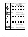
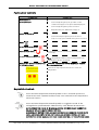
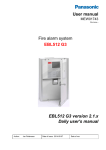
EP203 AUTOMATIC EXTINGUISHER PANEL User Manual and Log Book Approved Document No. DFU0002031 Rev 1 EP203 AUTOMATIC EXTINGUISHER PANEL CONTE NTS IMPORTANT S AF E TY NOT E S ................................................................... 3 BASIC OVERVIEW AND KEY FE AT URE S .................................................... 4 CONTROLS & INDICATORS ...................................................................... 5 LCD Status Display Unit ...............................................................................................................................5 LED Indicators................................................................................................................................................5 Pushbutton Controls.....................................................................................................................................7 Keyswitch Controls .......................................................................................................................................7 ACCESSING T HE ME NU CONTROLS .......................................................... 8 Overview ........................................................................................................................................................8 Selecting the Menus and Sub Menus ........................................................................................................8 General User Controls (Access Level 1) .....................................................................................................9 Authorised User Controls (Access Level 2)............................................................................................. 10 FIRE AL ARM/EXTINGUIS HER P ANE L LOG BOOK ...................................... 1 4 INS T ALL ATION CERTIFICAT E .................................................................. 1 9 COMMISSIONING CERTIFICAT E ............................................................... 2 0 FIGURES Figure 1 : Front Panel Controls and Indicators ..................................................................................................5 Figure 2 : Overview of Access Levels 1 & 2 Menus............................................................................................8 ©2007. No responsibility can be accepted by the manufacturer or distributors of this range of extinguisher panels for any misinterpretation of an instruction or guidance note or for the compliance of the system as a whole. The manufacturer’s policy is one of continuous improvement and we reserve the right to make changes to product specifications at our discretion and without prior notice. E&OE. Page 2 of 20 • EP203 AUTOMATIC EXTINGUISHER PANEL USER MANUAL • Approved Document No. DFU0002031 Rev 1 EP203 AUTOMATIC EXTINGUISHER PANEL IMPORTANT SAFETY NOTES The EP203 Automatic Extinguisher Panel (hereafter called the EP203 panel) is safe to operate provided it has been installed in compliance with the manufacturer’s instructions and used in accordance with this manual. Le tha l v ol ta ge s a re pre se nt i n s i de the pa nel . DO NOT operate the EP203 panel with its enclosure open. There is no need to open the enclosure except to carry out commissioning, engineering or maintenance work. This work must only be carried out by competent service personnel who are fully conversant with the contents of the separate installation manual for this product and have the necessary skills for maintaining this equipment. If the enclosure is damaged in any way, expert advice should be sought regarding its repair. Regular servicing of the EP203 panel and extinguishing system is highly recommended, preferably on a continuous maintenance contract and by a competent organisation. A full itemised report of the installation should be obtained at least annually. Approved Document No. DFU0002031 Rev 1 • EP203 AUTOMATIC EXTINGUISHER PANEL USER MANUAL • Page 3 of 20 EP203 AUTOMATIC EXTINGUISHER PANEL BASIC OVERVIEW AND KEY FEATURES The EP203 panel acts as both a conventional fire alarm panel and an automatic extinguisher control panel. The EP203 panel’s features include the following: • Time-stamped event log • Abort option for cancelling the extinguishant release sequence • Front-panel mounted LCD Status Display Unit displays system status and facilitates system programming • Front-panel mounted extinguisher release button and two keyswitches; one to enter access mode and one to toggle between automatic/manual modes of operation • Three-zone conventional detector circuits, line monitored for open and short circuit faults. Any zone combination can be programmed to activate an alarm and initiate the extinguishant release sequence • Three conventional alarm sounder circuits (two x 1st stage, one x 2nd stage), line monitored for open and short circuit faults • Monitored inputs for: Manual Release, Flow Switch, Low Pressure, Mode, Hold and Abort • Auxiliary outputs for: Fire, Local Fire, Extract, 1st Stage, 2nd Stage, Fault • Extinguishing output supports up to 2 x solenoids, or multiple ‘Metrons™’ • Adjustable extinguishant release time delay, duration and flooding time • Alarm counter to record the number of times the panel has been in an alarm state • Optional Relay Output Card providing additional relay outputs for: Reset, Mode, Discharged, Hold and Abort • Connections for up to eight Remote Status Units (RSU) which provide remote indication of system status on a Status Display Unit with mode select and manual extinguisher release • Connections for up to eight Economy Status Units (ESU) to provide remote indication of system status with mode select. • Pushbutton and keyswitch entry to two access levels (displayed on the Status Display Unit). Access Level 1 (AL1) is for general users, Access Level 2 (AL2) is for authorised users. Page 4 of 20 • EP203 AUTOMATIC EXTINGUISHER PANEL USER MANUAL • Approved Document No. DFU0002031 Rev 1 EP203 AUTOMATIC EXTINGUISHER PANEL CONTROLS & INDICATORS The front of the EP203 panel has various LED indicators, pushbuttons, keyswitches and an LCD Status Display Unit, as shown in Figure 1 below: Note : P/B=Pushbutton, K/S=Keyswitch Figure 1 : Front Panel Controls and Indicators LCD St a tus Display Unit This unit provides system status information, counts down the time for extinguishant release and displays Access Levels 1 & 2 menu controls. LE D Indicators The LED indicators on the front of the panel give a comprehensive overview of the system’s current status. Any fire and fault conditions are clearly displayed, disablements highlighted and the status of all inputs and outputs displayed. The table below summarises the various indicators and what they mean in their various states. INDICATO R (Gene ral F i re) S TATUS Flashing Red DES C R IPTI ON The panel has detected a fire alarm condition on a fire zone F i re Z o n e s Steady Red The fire alarm has been silenced Flashing Red A fire alarm condition has been detected on the zone(s) flashing 1 – 2 – 3 Steady Red The fire alarm has been silenced on the zones lit steady Hol d Flashing Yellow A hold input has been received at the panel F i r st S ta g e O u t p u t Steady Red First stage extinguishant output has been activated. R elea se I m m i ne n t ( x2) Steady Red Countdown timer to extinguishant release has started E xt i n g u i s h a n t Steady Red R elea se d A flow switch input (from a flow switch on the extinguishant cylinder) is received at the panel Ab o rt Steady Yellow An abort input has been received at the panel Genera l Disa b le me n t Steady Yellow Part of the system has been manually disabled and/or one or more of the fire zones has a delay applied to them Approved Document No. DFU0002031 Rev 1 • EP203 AUTOMATIC EXTINGUISHER PANEL USER MANUAL • Page 5 of 20 EP203 AUTOMATIC EXTINGUISHER PANEL INDICATO R Z o n e F a u l t/Disa b le/Te st S TATUS Flashing Yellow DES C R IPTI ON Faulty wiring, or detector removed from base, detected on the zones flashing. 1 – 2 – 3 Steady Yellow The zones lit steady have been disabled Flashing Yellow The zones flashing are in test mode Steady Yellow Extinguishant release output has been disabled Steady Yellow Manual release facility has been disabled Steady Yellow First stage contact has been disabled Steady Yellow Second stage contact has been disabled S o u n d er Disa ble me n t Steady Yellow Indicates all panel sounders are disabled Man u al O n l y Steady Yellow Indicates the status of the extinguishant system is E xt i n g u i s h a n t R elea se Disa ble me n t Man u al R elea se Disa ble me n t F i r st S ta g e O u t p u t Disa ble me n t S ec o n d S ta g e O u t p u t Disa ble me n t “Manual Only” mode Man u al & Aut o m a tic Steady Yellow Indicates the status of the extinguishant system is “Manual & Automatic” mode S u p p l y P re se n t Steady Green The panel is supplied with power P ower S u p p l y F a u l t Flashing Yellow The panel has detected a fault with its power supply, or back-up batteries Accesse d Steady Yellow The panel-mounted keyswitch has been turned to the “accessed” position and the panel is in Access Level 2 (authorised user level). Test Flashing Yellow The panel is in test mode Genera l F a u l t Flashing Yellow Indicates a fault has been detected on the system S y s te m Fa u l t Flashing Yellow The panel has detected a microprocessor fault. Delay s Steady Yellow Delays have been programmed into the panel Flashing Yellow A delay is currently running Flashing Yellow Faulty wiring (short or open circuit) has been S o u n d er Fa u l t detected on the panel’s sounder circuits Flo o di n g Zo ne Fault Steady Yellow The alarm sounders have been disabled Flashing Yellow Indicates a short or open circuit on extinguishant output. L ow P res s u r e F a u l t Flashing Yellow Indicates there is low pressure in the extinguishant system, or there is a short/open circuit fault on the low pressure switch input Page 6 of 20 • EP203 AUTOMATIC EXTINGUISHER PANEL USER MANUAL • Approved Document No. DFU0002031 Rev 1 EP203 AUTOMATIC EXTINGUISHER PANEL Pushbutton Controls PUSHBUTTON DES C R IPTI ON Sc r o l l (u p) / Dependent on the status of the panel, these pushbuttons: Sc r o l l (d ow n) • scroll vertically through any fire, pre-alarm or fault conditions that appear on the panel’s Status Display Unit Esca pe / Accep t • scroll vertically through the panel’s user menus • manipulate date, time, disablement settings, etc. Dependent on the status of the panel, these pushbuttons: • scroll horizontally through the panel’s user menus • escape or accept options available in the panel’s user menus. Men u Provides access to the Access Level 1 and 2 menus. S i le nce I n t er n a l S o u n d er Silences the panel’s internal sounder at anytime. C o n t r o l Pa n el R ese t Resets the panel after the sounders have been silenced (Access Level 2 only). S i le nce / Re s o u n d S o u n d e r s Silences or resounds the system’s sounders (Access Level 2 only). Note: This pushbutton will not silence 2nd stage alarm if the extinguishant is about to be released. E xt i n g u i s h er R elea se (p u s h b u t t o n s CAUTION: THESE PUSHBUTTONS MANUAL LY RE L EASE i n y el l ow h o u s i n g) THE EXTINGUISHANT. Pull down the flap and press both buttons to release the extinguishant. Key switch Controls Insert and turn the panel-mounted keyswitch to the “accessed” position to enter Access Level 2 (Authorised User level). Turn and remove the keyswitch to exit Access Level 2. Insert and turn the panel-mounted keyswitch to toggle the mode of the extinguishant system between “Manual Only” and “Manual & Automatic”. NOT E: WHEN THE PANEL IS IN MANUAL MODE, E X TINGUISHANT CANNOT BE RELEASED BY AUT OMATIC FIRE DET ECTI ON. MODE SELECT K E YSWI TCHES ARE ALSO MOUNTED ON REMO T E STATUS UNITS (RSU) AND ECONOMY STATUS UNITS (ESU) AND O T HER DEVICES. ANY ONE K E YS WITCH IN THE MANUAL P OSITION TAK ES CONTROL OF THE SYSTEM MODE. Approved Document No. DFU0002031 Rev 1 • EP203 AUTOMATIC EXTINGUISHER PANEL USER MANUAL • Page 7 of 20 EP203 AUTOMATIC EXTINGUISHER PANEL ACCESSING THE MENU CONTROLS Overview Two levels of menu controls are available on the EP203 panel; Access Level 1 for General Users and Access Level 2 for Authorised Users. All menus are displayed at the Status Display Unit, as detailed below: Access Level 1 Menu Access Level 2 Menu Figure 2 : Overview of Access Levels 1 & 2 Menus Selecting the Menus and Sub Menus 1. To enter Access Level 1 menu press the Menu pushbutton, or to enter Access Level 2 menu turn the panel-mounted keyswitch to the “accessed” position. 2. Press the Scroll (up) and Scroll (down) buttons to highlight a menu. 3. Press the Accept button to select a menu. 4. Press the Accept button to select a sub menu (if available). 5. If applicable, press the Scroll (up) and Scroll (down) buttons to scroll the display through all active conditions (faults, disablements, tests, ). 6. Press the Escape button to return to the previous menu. 7. To exit Access Level 1 press the Escape button. N ote : The panel will automatically exit Access Level 1 after approx. 15 secs. of inactivity. To exit Access Level 2 turn the panel-mounted keyswitch to the NOT “accessed” position. Page 8 of 20 • EP203 AUTOMATIC EXTINGUISHER PANEL USER MANUAL • Approved Document No. DFU0002031 Rev 1 EP203 AUTOMATIC EXTINGUISHER PANEL Gen e r al Us e r Controls (Acces s Lev el 1 ) The functions that can be performed in Access Level 1 are: • Manually activate the extinguisher release • Mute the internal sounder. In addition, by pressing the Menu pushbutton, the Status Display Unit displays the following menu: Note : All Access Level 1 menus are available to an Access Level 2 user. MENU DES C R IPTI ON Dis p la y Fa u l t s Displays all faults on the system Dis p la y Dis/M nt Displays all disablements on the system Z o n es I n Tes t Displays all detection zones that are in test mode on system L a m p Te st Illuminates all front panel LED indicators Alarm C o u n te r Displays the number of times a fire alarm condition has occurred on the panel D i sp la y Faul t s 1. In Access Level 1, select the Display Faults menu. The panel displays all active faults on the system. (e.g. Zone 1 O/C Fault, Zone 2 S/C Fault, etc.) 2. Scroll the display through all active faults using the Scroll (up) and Scroll (down) buttons. 3. Press the Escape button to return to the Access Level 1 menu. D i sp la y D i s /M nt The Display Disablements menu displays all active disablements on the system. An Access Level 2 user sets disablements. 1. In Access Level 1, select the Display Dis/mnt menu. The panel displays all active disablements on the system (e.g. Zone 1 disabled, etc.) 2. Scroll the display through all active disablements using the Scroll (up) and Scroll (down) buttons. 3. Press the Escape button to return to the Access Level 1 menu. Zone s i n Te st This menu displays all detection zones that are currently in test mode on the system. A system engineer can only put zones into test mode. 1. In Access Level 1, select the Zones in Test menu. The panel displays all zones currently in test on the system (e.g. Zone 1 is on Test, etc.) 2. Scroll the display through all active zones in test using the Scroll (up) and Scroll (down) buttons. 3. Press the Escape button to return to the Access Level 1 menu. Approved Document No. DFU0002031 Rev 1 • EP203 AUTOMATIC EXTINGUISHER PANEL USER MANUAL • Page 9 of 20 EP203 AUTOMATIC EXTINGUISHER PANEL La m p Test All LED indicators can be tested at anytime by selecting using this menu. 1. In Access Level 1, select the Lamp Test menu. All the panel’s LEDs will illuminate steady for approx. 2 secs. The panel’s internal sounder will also sound. If any LEDs fail to illuminate report the fault to the designated site engineer and make a note in the Log Book. 2. On completion, the display returns to the Access Level 1 menu. A la rm Co un te r 1. In Access Level 1, select the Alarm Counter menu. The total number of times the panel has been in a fire alarm condition is displayed. 2. Press the Escape button to return to the Access Level 1 menu. Authoris ed Us e r Controls (Acce s s Lev el 2) The functions that can be performed in Access Level 2, by turning the panel-mounted keyswitch to the “accessed” position, are: • Manually activate the extinguisher release • Mute the internal sounder • Silence the alarm sounders • Resound the alarm sounders • Reset an alarm condition. In addition, the Status Display Unit displays the following menu: MENU SU B MENU DES C R IPTI ON Dis p la y Fa u l t s - See Access Level 1 Dis p la y Dis/M nt - See Access Level 1 Z o n es I n Tes t - See Access Level 1 L a m p Te st - See Access Level 1 Alarm C o u n te r - S et Ti me /Date - E ve n t L o g Dis p C o n t ras t Disa ble me n t s Displays the number of times a fire alarm condition has occurred on the panel. Also, resets the counter. Adjusts the panel’s date & time settings Show Log Displays the panel’s event log Log Reset Resets the panel’s event log - Adjusts the contrast of the Status Display Unit Disable Exting Disables/enables the extinguishant system Disable Zone Disables/enables detection zones Disable Sounder Disables/enables fire sounders Disable Input Disables/enables monitored inputs Disable Relay Disables/enables auxiliary relay outputs Disable RSU Disables/enables Remote Status Units Page 10 of 20 • EP203 AUTOMATIC EXTINGUISHER PANEL USER MANUAL • Approved Document No. DFU0002031 Rev 1 EP203 AUTOMATIC EXTINGUISHER PANEL A la rm Co un te r 1. In Access Level 2, select the Alarm Counter menu. The total number of times the panel has been in a fire alarm condition (since last reset) is displayed. 2. Press the Escape button to return to the Access Level 2 menu or, to clear the alarm counter, press the Accept button. The panel requests confirmation to clear to todays date. 3. Press the Accept button to reset the counter. The panel will start counting any new fire conditions from the current date. A confirmation message confirms the change has been made and the display returns to the Access Level 2 menu. Se t T i me / Da te 1. In Access Level 2, select the Set Time/Date menu. The panel’s current time setting is displayed. 2. Use the Scroll (up) and Scroll (down) buttons to adjust the hour (the panel has a 24 hour clock). 3. When the correct hour is displayed, press the Accept button to move to the minutes field. 4. Use the Scroll (up) and Scroll (down) buttons to adjust the minutes. 5. When the correct time is displayed, press the Accept button to alter the date. 6. Use the Scroll (up), Scroll (down) and Accept buttons to set the day/month/year, as appropriate. 7. When correct, press the Escape button to return to the Access Level 2 menu. Event L og 1. In Access Level 2, select the Event Log menu, select Show Log sub menu. The panel’s last event log is displayed. 2. Use the Scroll (up) and Scroll (down) buttons to view the previously saved events. When the log is full, the newest record replaces the oldest record. Events are listed in chronological order. 3. Press the Escape button to return to the previous menu. 4. To reset the panel’s event log, in Access Level 2, select the Event Log menu, then select Log Reset sub menu. The panel requests confirmation to erase the event log. 5. Press the Accept button to confirm and the event log is cleared from the panel’s memory. 6. Press the Escape button to return to the previous menu. D i sp Con t ra st 1. In Access Level 2, select the Disp Contrast menu. The panel’s current display contrast is displayed. 2. Use the Scroll (up) and Scroll (down) buttons to adjust the contrast of the Status Display Unit. 3. Press the Accept button to confirm the new setting and return to the Access Level 2 menu. Approved Document No. DFU0002031 Rev 1 • EP203 AUTOMATIC EXTINGUISHER PANEL USER MANUAL • Page 11 of 20 EP203 AUTOMATIC EXTINGUISHER PANEL Dis ablem ent s The Disablements menu allows the temporary disabling, or enabling of the extinguishant system, detection zones, sounders, monitored inputs, relays and RSUs. Typically used when there are input/output faults and for system testing. Any active disablements are displayed at the EP203 panel by the General Disablement and relevant disablement yellow LEDs lit steady. Note : It is recommended all disablements are immediately enabled when no longer required as they can have a major effect on how the system works. D i sa ble Ex t i ng This sub menu allows the disabling/enabling of the extinguishant system. 1. From the Disablements menu, select the Disable Exting sub menu. 2. Press the Accept button to disable/enable the extinguishant system. 3. Press the Escape button to return to the Disablements menu. Note : ‘Exting System Disabled’ will also be displayed at any Remote Status Units (RSUs) on the system. D i sa ble Zone This sub menu allows the disabling/enabling of one or more of the panel’s three detection zones. Disabled zones do not report fire or fault conditions. 1. From the Disablements menu, select the Disable Zone sub menu. 2. Select the detection zone(s) to be disabled/enabled using the Scroll (up) and Scroll (down) buttons. 3. Press the Accept button to disable/enable a selected zone. 4. Press the Escape button to return to the Disablements menu. D i sa ble S ounde r This sub menu allows the disabling/enabling of the fire sounders from sounding in a fire condition. 1. From the Disablements menu, select Disable Sounder. 2. Press the Accept button to disable/enable the sounder circuit. 3. Press the Escape button to return to the Disablements menu. D i sa ble I npu t This sub menu allows the disabling/enabling of one or more of the panel’s six monitored inputs: Manual Release, Flow Switch, Low Pressure, Mode Switch, Hold and Abort. 1. From the Disablements menu, select Disable Input. 2. Select the input(s) to be disabled/enabled using the Scroll (up) and Scroll (down) buttons. 3. Press the Accept button to disable/enable the selected input. 4. Press the Escape button to return to the Disablements menu. Page 12 of 20 • EP203 AUTOMATIC EXTINGUISHER PANEL USER MANUAL • Approved Document No. DFU0002031 Rev 1 EP203 AUTOMATIC EXTINGUISHER PANEL D i sa ble Re lay This sub menu allows the disabling/enabling of one or more of the panel’s six auxiliary relay outputs: Fire, Local Fire, Extract, 1st Stage, 2nd Stage and Fault. Note : If a Relay Output Card is fitted, this sub menu also allows the disabling/enabling of one or more of the card’s five relay outputs: Reset, Mode, Discharged, Hold and Abort. 1. From the Disablements menu, select Disable Relay. 2. Select the relay output(s) to be disabled/enabled using the Scroll (up) and Scroll (down) buttons. 3. Press the Accept button to disable/enable the selected relay output. 4. Press the Escape button to return to the Disablements menu. D i sa ble RS U This sub menu allows the disabling/enabling of one or more of the panel’s Remote Status Units. 1. From the Disablements menu, select Disable RSU. 2. Select the RSU(s) to be disabled/enabled using the Scroll (up) and Scroll (down) buttons. 3. Press the Accept button. The panel requests confirmation. 4. Scroll (down) to confirm the change. 5. Press the Accept button to disable/enable the selected RSU. The Disablements menu is displayed. Note : ‘RSU Disabled’ will be displayed at the RSU that has been disabled. Approved Document No. DFU0002031 Rev 1 • EP203 AUTOMATIC EXTINGUISHER PANEL USER MANUAL • Page 13 of 20 EP203 AUTOMATIC EXTINGUISHER PANEL FIRE ALARM/EXTINGUISHER PANEL LOG BOOK It is recommended that this log book be maintained by a responsible person, who should ensure that every entry is properly recorded. In the UK, this is necessary to satisfy the recommendations of BS5839-1: 2002, compliance with which may be a requirement of legislation. If your premises are certificated under the Fire Precautions Act 1971, failure to keep a suitable log book may be a breach of the requirements of the certificate, which is a criminal offence. In order to satisfy the requirements of BS5839-1: 2002, the following must be recorded: Name of the responsible person Brief details of the maintenance arrangements Dates and times of all tests, including fire drills Dates and times of all fires to which the system responds Dates and times of all false alarms Causes, circumstances surrounding, and category of false alarms (if known) The identity of any manual call point or fire detector that triggers any of the above fire alarm/extinguisher signals (if known) Dates, times and type of all faults and defects Dates and times of all maintenance (e.g. service visit or non-routine attention). USER: SITE ADDRESS: RESPONSIBLE PERSON(S) ON SITE: THE SYSTEM WAS DESIGNED BY: THE SYSTEM WAS INSTALLED BY: THE SYSTEM WAS COMMISSIONED BY: THE SYSTEM WAS ACCEPTED BY: VERIFICATION WAS UNDERTAKEN BY: F O R SE R V I CE (DETAILS OF WHO YOU SHOULD CONTACT IF MAINTENANCE IS REQUIRED) THE SYSTEM IS MAINTAINED UNDER CONTRACT BY: Company: __________________________________________________________________________ Address: ___________________________________________________________________________ ____________________________________________________________________________________ Contact No: ______________________________________ Expiry Date: ______________________ NORMAL HOURS (MON-FRI) TEL: ______________________________________________________ OUTSIDE NORMAL HOURS TEL: _______________________________________________________ MANNED CENTRE TEL: ______________________________________________________________ MANNED CENTRE CODE: ____________________________________________________________ NORMAL MAXIMUM ATTENDANCE TIME FOR A MAINTENANCE TECHNICIAN IS: __________ EXPENDABLE COMPONENT REPLACEMENT PERIODS (LIST): Page 14 of 20 • EP203 AUTOMATIC EXTINGUISHER PANEL USER MANUAL • Approved Document No. DFU0002031 Rev 1 EP203 AUTOMATIC EXTINGUISHER PANEL Details of tests (including fire drills), actual fire alarms, disablements, enablements and faults should be recorded here. False alarms and maintenance work should be recorded on page 18. DATE TIME E V ENT e.g. test, fire alarm signal, fault Z ONE DEVICE ACTION REQUIRED COMPLE T ED INITIALS Approved Document No. DFU0002031 Rev 1 • EP203 AUTOMATIC EXTINGUISHER PANEL USER MANUAL • Page 15 of 20 EP203 AUTOMATIC EXTINGUISHER PANEL DATE TIME E V ENT e.g. test, fire alarm signal, fault Z ONE DEVICE ACTION REQUIRED COMPLE T ED INITIALS Page 16 of 20 • EP203 AUTOMATIC EXTINGUISHER PANEL USER MANUAL • Approved Document No. DFU0002031 Rev 1 EP203 AUTOMATIC EXTINGUISHER PANEL DATE TIME E V ENT e.g. test, fire alarm signal, fault Z ONE DEVICE ACTION REQUIRED COMPLE T ED INITIALS Approved Document No. DFU0002031 Rev 1 • EP203 AUTOMATIC EXTINGUISHER PANEL USER MANUAL • Page 17 of 20 EP203 AUTOMATIC EXTINGUISHER PANEL Fa l se A la r m s BRIEF CIRCUMS T ANC E S D AT E TIME ZO NE DE V ICE T H AT TRIGG ERE D A L ARM SIG N A L CAU S E (IF K NO W N) (WH ERE CA U S E I S U N K NO W N RECO RD ACTI VITIE S IN T H E ARE A) MAINTE N A NCE F I N DIN G S O F CAT E GO RY VI S I T REQ UIRED ? MAINTE N A NCE O F F A L S E TEC H NICIAN A L ARM S (YE S O R NO) F UR T HER ACTIO N REQ UIRED DO NE PLEASE TICK Mainte na nce Wo rk D AT E TIME ZO NE (WH ERE A P P LICAB L E) DE V ICE (WH ERE A P P L ICAB L E) REA S O N S F O R WO RK WO R K CARRIED O UT F UR T HER WO R K REQ UIRED S I G NA T URE Page 18 of 20 • EP203 AUTOMATIC EXTINGUISHER PANEL USER MANUAL • Approved Document No. DFU0002031 Rev 1 EP203 AUTOMATIC EXTINGUISHER PANEL INSTALLATION CERTIFICATE BS5839-1:2002 recommends that certificates be issued for all aspects of the fire alarm/extinguisher system including design, installation, commissioning, acceptance, verification (optional) and maintenance. Therefore, before this user manual is handed over, the following installation certificate and the commissioning certificate (overleaf) should be completed as appropriate by the relevant installation/commissioning engineer(s). Please ensure that the system set-up data chart and the relevant parts of the system Log Book are also completed as appropriate. For countries outside the UK, different certification requirements may apply. Certificate o f I NSTALLATI O N f o r t he fi re alar m/ ex ti n gui s he r sy s te m at: Address: ______________________________________________________________________________________ _______________________________________________________________________________________________ _______________________________________________________________________________________________ I/we being the competent person(s) responsible (as indicated by my/our signatures below) for the installation of the fire alarm/extinguisher system, particulars of which are set out below, CERTIFY that the said installation for which I/we have been responsible complies to the best of my/our knowledge and belief with the specification described below and with the recommendations of Section 4 of BS5839-1:2002, except for the variations, if any, stated in this certificate. Name (in block letters): ________________________________________________________________________ Position (in block letters): ______________________________________________________________________ Signature: ____________________________________________________________________________________ Date: _________________________________________________________________________________________ For and on behalf of: __________________________________________________________________________ Address & postcode: ___________________________________________________________________________ _______________________________________________________________________________________________ _______________________________________________________________________________________________ The extent of the liability of the signatory is limited to the system described below. Extent of installation work covered by this certificate: _______________________________________________________________________________________________ _______________________________________________________________________________________________ _______________________________________________________________________________________________ _______________________________________________________________________________________________ Specification against which the system was installed: _______________________________________________________________________________________________ _______________________________________________________________________________________________ _______________________________________________________________________________________________ _______________________________________________________________________________________________ _______________________________________________________________________________________________ Variations from the specification and/or Section 4 of BS5839-1:2002 (see BS5839-1:2002, Clause 7): _______________________________________________________________________________________________ _______________________________________________________________________________________________ _______________________________________________________________________________________________ _______________________________________________________________________________________________ _______________________________________________________________________________________________ Wiring has been tested in accordance with the recommendations of Clause 38 of BS5839-1: 2002. Test results have been recorded and provided to: ________________________________________________ Unless supplied by others, the “as fitted” drawings have been supplied to the person responsible for commissioning the system (see 36.2m) of BS5839-1: 2002: ________________________________________ Approved Document No. DFU0002031 Rev 1 • EP203 AUTOMATIC EXTINGUISHER PANEL USER MANUAL • Page 19 of 20 EP203 AUTOMATIC EXTINGUISHER PANEL COMMISSIONING CERTIFICATE BS5839-1:2002 recommends that certificates be issued for all aspects of the fire alarm/extinguisher system including design, installation, commissioning, acceptance, verification (optional) and maintenance. Therefore, before this user manual is handed over, the following commissioning certificate and the installation certificate (overleaf) should be completed as appropriate by the relevant installation/commissioning engineer(s). Please ensure that the system set-up data chart and the relevant parts of the Log Book are also completed as appropriate. For countries outside the UK, different certification requirements may apply. Certificate o f C OMMISSIO NI NG f o r t he fi re alar m/ ex ti n gui s he r sy s te m at: Address: ______________________________________________________________________________________ _______________________________________________________________________________________________ I/we being the competent person(s) responsible (as indicated by my/our signatures below) for the commissioning of the fire alarm/extinguisher system, particulars of which are set out below, CERTIFY that the said work for which I/we have been responsible complies to the best of my/our knowledge and belief with the specification described below and with the recommendations of Clause 39 of BS5839-1: 2002, except for the variations, if any, stated in this certificate. Name (in block letters): ________________________________________________________________________ Position (in block letters): ______________________________________________________________________ Signature: ____________________________________________________________________________________ Date: _________________________________________________________________________________________ For and on behalf of: __________________________________________________________________________ Address & postcode: ___________________________________________________________________________ _______________________________________________________________________________________________ The extent of the liability of the signatory is limited to the system described below. Extent of system covered by this certificate: _______________________________________________________________________________________________ _______________________________________________________________________________________________ Variations from the recommendations of Clause 39 of BS5839-1:2002 (see BS5839-1:2002, Clause 7): _______________________________________________________________________________________________ _______________________________________________________________________________________________ All equipment operates correctly. Installation work is, as far as can reasonably ascertained, of an acceptable standard. The entire system has been inspected and tested in accordance with the recommendations of 39.2c of BS5839-1:2002. The system performs as required by the specification prepared by: ___________________________ a copy of which I/we have been given. Taking into account the guidance contained in Section 3 of BS 5839-1:2002, I/we have not identified any obvious potential for an unacceptable rate of false alarms. The documentation described in Clause 40 of BS5839-1:2002 has been provided to the user. The following work should be completed before/after (delete as applicable) the system becomes operational: _______________________________________________________________________________________________ _______________________________________________________________________________________________ The following potential cause(s) of false alarms should be considered at time of next service visit: _______________________________________________________________________________________________ _______________________________________________________________________________________________ Before the system becomes operational, it should be soak tested in accordance with the recommendations of 35.2.6 of BS5839-1:2002 for a period of: _________________ (enter a period of either one week, such period as required by the specification, or such period as recommended by the signatory of this certificate, whichever is the greatest, or delete if not applicable). Page 20 of 20 • EP203 AUTOMATIC EXTINGUISHER PANEL USER MANUAL • Approved Document No. DFU0002031 Rev 1