1
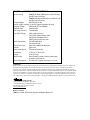
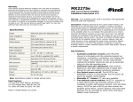
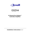
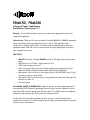
PRM150, PRM200 Advanced Power Conditioners Installation Instructions v1.1 Warning: To be installed and/or used in accordance with appropriate electrical codes and regulations Introduction: Thank you for your purchase of a Knöll PRM150 or PRM200 Advanced Power Conditioner and congratulations on your choice. This specially made conditioner is designed specifically to reduce noise and hum pickup by sensitive equipment when ultra-low-noise is a must as well as surge suppression to protect your valuable electronics. FEATURES: • • • • • • • PRM150 rated for 15 amps, PRM200 rated for 20 amps (with special power plug) Push button or 4-24 VDC trigger power on/off 2210 Joules surge protection Eight rear panel, heavy duty AC outlets includes two unswitched, and six sequence delayed switched outlets with Digital Isolated Outlets Main power cord is a 10 foot, ultra heavy duty 14 Ga. (PRT200 8 foot 12 ga.) for easy access to a wall socket Rear panel cable TV connectors for surge protection and noise filtering with satellite or cable TV One rack space ADVANCED SURGE SUPPRESSION- Edge-of-the-art two level suppression with an astounding 2210 Joules of lightning protection (most current competitive units only have 360) in the AC power line! Add the cable TV, satellite dish and telephone line protection and you have 3590 joules of total protection! In the event the unit does not power up after a surge, a small internal board replacement may be all it takes to keep on protecting your sound and picture quality as well as your investments. Coaxial surge suppression is often over looked. A convenient “F” connector is provided both for cable TV and the satellite dish. This allows full surge protection through a low loss pass through connection. Telephone line surge protection is provided to bring an added measure of safety to your home. An RJ connector is provided for both in and out connections. DELAYED 3 STAGE POWER TURN-ON/OFF- Powering up large systems, especially those with separate power amplifiers can be a problem. The source components should be switched on first and second, followed by the power amplifiers. The PRM150 and PRM200 have two outlets on all the time. When the power up command has been received (by the trigger or the power button on the front panel) two more outlets turn on, two seconds later the last 2 (of eight total) outlets turn on. This eliminates the annoying (and potentially dangerous) speaker pop that occurs when the amplifier is turned on before the source components. The power off cycle reverses the order for proper system shutdown. The PRM150 and PRM200 can be dealer adjusted with four-second delays instead of two-second delays. DIGITAL ISOLATED OUTLETS- All outlets use a state of the art emi filter system that isolate digital components (with noisy high speed microprocessors), such as DVD and laser disc players, from delicate analogue equipment like preamplifiers and power amplifiers. The result is cleaner, more three-dimensional sound and less harshness in digital audio. VERSATILE POWER ON/OFF OPTIONS- With the PRM150 and the PRM200, the system can be turned on with a touch of the front panel power button. In larger, home-automated systems, a simple 4-24V DC signal will also turn on all switched outlets. A low cost 9-12 VDC power supply allows full system control through any switched AC outlet, such as a remote controlled preamplifier or receiver. Turn on one component (with a switched AC outlet) and an entire system can be activated simply, and safely. Installation: The PRM200 power source connection must be adequate for use at 20 amps. We recommend a properly grounded 30-amp circuit, wired with 10-gauge wiring, if continuous operation near 20 amps is anticipated. A dedicated (nothing else connected) 20-amp circuit is the minimum acceptable to comply with NEC requirements. Consult a qualified electrician if in doubt. Please note the PRM200 cord plug requires a different style outlet than a conventional style 15-amp outlet. 3-24vdc TRIG G E R O N VIA 3.5 mm M O N O J A C K 12 0 VAC 120VAC Input PR M 1 5 0 MAX 15 AMPS PRM200 MAX 20 AMPS DELAY MAX T H ES E T W O O U T LE TS T U R N O N 4 S E CO N D S A F T E R PO W E R U P A N D T U RN O F F I M M E D IA T E L Y A F T ER P O W E R D OW N . A M P S A N D SUB SAR E C O N N E CT E D H E R E DELAY MED DELAY MIN UNSWITCHED T H ESE TW O OU TLETS T U RN ON 2 SECONDS A FTER POW ER UP AND T U RN OF F 2 SECONDS A FTER POW ER DOW N. A MPS AND DVD’S ARE C ONNECTED HERE THESE TW O OU TLETS TURN O N IMM EDIATELY AT PO WER UP AND ARE THE LA ST TO TU RN OFF AT PO WER DOWN. AUDIO PROCES SORS, CD AND VIDEO A RE CO NN ECTED HERE THESE TW O O U T L E T S A RE ON AL L T H E T I M E . VCR, CLOCK S A N D S TAN DBY E Q U I P M E N T A RE CONN E C T E D H E R E C A B L E TV INPUT C O N NECT CABLE B E F O RE ANY TV’S O R V CR’S ETC. SAT DISH INPUT CONNECT TO SAT DISH SAT DISH OUTPUT CONNECT TO SAT DISH RECEIVER T ELEPHONE INPUT AND OUTPUT. CONNECT EITHER J ACK TO THE C A B L E T V O U T P U T T ELEPHONE LINE BEFORE C O N N E C T TO T V ’S ANY TELEPHONE OR MODEM V C R ’S , S P L IT T E R S I N THE HOME, THEN CONNECT ET C . IN H O M E. T HE OTHER JACK TO HOME EQ UIPMENT. ONLY THE CENTER PAIR IS ACTIVE The PRM150 requires a dedicated properly grounded 15-amp circuit to operate at capacity. We suggest that a dedicated 15-amp breaker be installed at the breaker box for use with the PRM150. It is best if the PRM150 or PRM200 is located with other equipment so that extension cords are not required. Heat is not a consideration when placing the power conditioner. Plug all the AC power cords from all components directly into the back of the power conditioner. This offers full line conditioning and filtering for your entire system. Keep in mind that Knoll power conditioners can only do so much in the cases of lightning strikes and large surges. If your area is prone to lightning strikes and large surges we strongly suggest you have a whole house lightning arrestor installed. Ask you power provider for more information. The un-switched outlets are for components that require full time power such as VCR’s or TV’s. If you wish to turn on your system via an existing component with remote control access (such as a receiver with a switched ac outlet on the back), plug your receiver into the un-switched outlet on the power conditioner (and read the section below on rear panel trigger). Delayed Turn On’s. When the power conditioner is turned on, the two outlets labelled “Delay Min” turn on immediately (along with the unswitched outlets already turned on). About two seconds later the next two outlets labelled “Delay Med” turn on. About two seconds later (four seconds from when the power conditioner was first turned on) the last two outlets labelled “Delay Max” turn on. Typically ancillary equipment such as equalizers, processors, DVDs etc. are connected to the outlets labelled Delay Min and Delay Med. Typically larger power amplifiers are connected to the outlets labelled “Delay Max” so that other equipment has time to stabilize before the amplifier gets power, seriously reducing loudspeaker clicks and pops. If multiple amplifiers are too powerful to connect to a single Knoll power conditioner, we suggest using a 12V DC wall wart power supply connected to the Delay Max outlet on the power conditioner and connect the wall wart to the amplifier trigger input(s). The amps are plugged into the wall and not to the power conditioner. If there is two larger amplifiers to be connected to this power conditioner, we suggest that one be connected to the outlets labelled Delay Med and the other to the outlets labelled Delay Max. If a longer eight-second turn on sequence instead of the standard four second start up sequence is required, your authorized Knoll dealer can remove an internal shunt to accomplish this. Power Down When the power down command is received by the Knoll Power Conditioner a reverse sequence to the power up is initiated. Immediately when the power down command is received, the outlets labelled “Delay Max” are shut off. Two seconds later, the outlets labelled “Delay Med” are shut off. Two seconds later, the outlets labelled “Delay Min” are shut off. The last two outlets labelled “Unswitched” are never shut off. Rear Panel Trigger The Knoll Power conditioner is equipped with a remote trigger activation to turn the power conditioner off and on (just like the front switch). When a 3-24 VDC or VAC constant signal (trigger) is present, the power conditioner will power up in sequence and stay on as long as the signal is present. When the trigger signal is lost, the power conditioner begins its power down sequence and stays off until either a trigger signal is reacquired or the front panel power button is pressed. When connecting to the trigger, polarity is unimportant. Fuses There is a single slow blow 15-amp fuse in the PRM150 and there is a single 20 amp slow blow fuse in the PRM200. As per safety regulations, only authorized and experienced service people, including Knoll factory personnel are authorized to change these fuses. DO NOT CHANGE these fuses for safety reasons. Cable TV and Satellite Dish For best protection, connect the cable TV when it first enters the home to the Knoll Power Conditioner F connector labelled Cable TV IN. Next connect up the rest of the home’s TV’s to the F connector labelled Cable TV OUT. If you have a lousy cable TV picture after this, check carefully that these were connected correctly. Likewise connect the satellite dish when it first enters the home to the Knoll Power Conditioner F connector labelled Sat Dish IN. Next connect the satellite dish receiver to F connector labelled Sat Dish OUT. Telephone Connection Connect a single telephone line pair to the Knoll Power Conditioner rear RJ connector. Connect the rest of the home’s telephone lines to the other RJ connector. Please note that even though there is room for three wire pairs only the centre pair is connected and protected. PRM150 and PRM200 SPECIFICATIONS Current rating: PRM150 15 amps (1800 watts at 60/120 VAC, 60 HZ) fuse protected. PRM200 20 amps (2400 watts at 60/120 VAC, 60 HZ) fuse protected. Voltage Ranges: 90-135 VAC 60 Hz Remote trigger voltage: 3-24 VDC (input impedance 1k ohm) Clamping Voltage 250v peak (175 volts RMS) Response time: 1 nanosecond Max Surge Current: 72,300 amps Max Spike Energy: 2210 joules (AC line) 740 joules (cable and sat dish) 640 joules (telephone line) 3590 joules total protection Noise attenuation: >25 dB at 200 kHz >60 dB at 5 mHz RF pass thru loss Less than 1 dB below 800 mHz Outlets: Eight rear Power consumption: Five watts maximum Dimensions: 1.75”H x 17” W x 11”D Weight 8 lbs (3.6 kg). Construction: Steel chassis, powder coated; glass epoxy printed circuit boards Power Consumption: 8.5 watts for display and control circuits, Warranty Knöll Systems warrants its products sold in the USA and Canada by authorized Knöll dealers to be free of defects in materials and workmanship. This warranty extends for three full years from the date of purchase by the original consumer. Any products returned to Knöll Systems and found to be defective by Knöll Systems within the warranty period will be repaired or replaced at Knöll Systems option, at no charge. Knöll Systems will not be responsible for the actual cost of installation or removal of the product, nor for any incidental or consequential damages. Some states do not allow the exclusion or limitation of incidental or consequential damages, so the above limitation may not apply to you. This warranty gives you specific legal rights. You may have additional legal rights that vary from state to state. Knoll Systems 145 Tyee Drive Point Roberts, WA 98281 11791 Machrina Way, #120 Richmond BC V7A 4V3 tel (604) 272 4555, fax (604) 272 5595 www.knollsystems.com Made in Canada PRM150 2002-2003 Knoll Systems All Rights Reserved