1
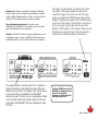
Warranty
Knoll Systems warrants MX6120 amplifiers sold in the USA and Canada by
authorized Knoll dealers to be free of defects in materials and manufacturing.
This warranty extends for three full years from the date of purchase by the
original consumer. Any products returned to Knoll Systems and found to be
defective by Knoll Systems within the warranty period will be repaired or
replaced at Knoll Systems decision, at no charge. Knoll Systems will not be
responsible for the actual cost of installation or removal of the product, nor for
any incidental or consequential damages. Some states do not allow the exclusion
or limitation of incidental or consequential damages, so the above limitation may
not apply to you. This warranty gives you specific legal rights. You may have
additional legal rights that vary from state to state.
MX6120 Amplifier
6 Channel Amplifier
Installation Instructions v1.0
Warning: To be installed and/or used in accordance with appropriate
electrical codes and regulations.
FOR USE WITH 6-16 OHM SPEAKERS ONLY
Specifications:
Line Inputs
6 Gold RCA jacks with adjustable gain
Input impedance
50k Ω
Outputs
detachable plug
Output power
120 watts RMS per channel (8 Ω)
Line Outputs
6 Gold RCA jacks, unbuffered
Peak output power
180 watts per channel (8 Ω)
Ideal impedance
8Ω
Frequency response
10 Hz - 40 kHz +/- 1dB (1w)
S/N ratio
over 108 dB A weighted (100 watts)
THD distortion
less than 0.1% 20 Hz to 20 kHz
IMD distortion
less than 0.01% 60 Hz 7 kHz 4:1
(SMPTE)
Trigger control
12 VDC 35mA on 3.5mm mono jack
Dimensions
17" x 3.5" x 11.5" (432 x 89 x 292mm)
Fan Noise
quiet 26 dBA
Power
900 watts at 117 VAC or 230 VAC
Weight
21 lbs (9.5 kg)
Note: Specifications subject to change without notice.
Knoll Systems
145 Tyee Drive Point Roberts, WA 98281
14-7163 Vantage Way, Delta BC V4G 1N1
Tel: (604) 940 1689, fax (855) 734 3363
Made in Canada/Fabrique au Canada
Description: The MX6120 is a member of the long line of Knoll multichannel amplifiers. Designed primarily for the custom install industry, it
is used to power speakers with different or similar sources in multiple
rooms. With 6 channels rated at 120 watts per channel at 8 Ω, the
MX6120 packs some serious punch. Each channel has a gain control.
The MX6120 can be turned on and off via the front panel power switch
or via the 12 VDC trigger. 1-3 MX6120 stereo channels can be
connected to a line level BUS input. MX6120 amplifiers designed to
meet the amplifier needs of custom installed systems where highquality sound is a specific requirement.
Key Features:
1. Size efficiency. The MX6120 consists of a total of 6 high
power amplifiers in one 3-1/2” high enclosure. Each power
amplifier channel can deliver 120 watts RMS into an 8-Ω load.
2. Automatic protection circuitry. Each MX6120 channel is
individually and fully protected against low impedance,
overheating, overloading, over voltage and under voltage. The
protection circuitry automatically restores the amplifier channel
as soon as its parameter returns to the safe operating area.
3. Individual input gain adjustment. Each channel features
an input gain adjustment pot to adjust each channel for gain
and speaker sensitivity variations.
4. External power on/off. The MX6120 can be turned off and
on by external controllers via its 12 VDC trigger jack.
5. Stackable 17" chassis. 19” rack ears available.
6. Bus Feature. Certain installations require that some or all of
the stereo channels play the same content. Instead of using Y
cords, the Knoll "BUS" connects any or all of channels 1-3 to the
stereo BUS inputs.
Important Safety Instructions:
1) Read these instructions.
2) Keep these instructions.
3) Read all warnings.
4) Follow all instructions.
5) Do not use this apparatus near water.
6) Clean only with dry cloth.
7) Do not block any ventilation openings. Install in accordance with the manufacturer’s
instructions.
8) Do not install near any heat sources such as radiators, heat registers, stoves, or
other apparatus (including amplifiers) that produce heat.
9) Do not defeat the safety purpose of the polarized or grounding-type plug. A
polarized plug has two blades with one wider than the other. A grounding type plug has
two blades and a third grounding prong. The wide blade or the third prongs are
provided for your safety. If the provided plug does not fit into your outlet, consult an
electrician for replacement of the obsolete outlet.
10) Protect the power cord from being walked on or pinched particularly at plugs,
convenience receptacles, and the point where they exit from the apparatus.
11) Only use attachments/accessories specified by the manufacturer.
12) Use only with the cart, stand, tripod, bracket, or table specified by the
manufacturer, or sold with the apparatus. When a cart is used, exercise caution when
moving the cart/apparatus combination to avoid injury from tip-over.
13) Unplug this apparatus during lightning storms or when not used for long periods of
time.
14) Refer all servicing to qualified service personnel. Servicing is required when the
apparatus has been damaged in any way, such as power-supply cord or plug is
damaged, liquid has been spilled or objects have fallen into the apparatus, the
apparatus has been exposed to rain or moisture, does not operate normally, or has
been dropped.
15).Under no circumstances should the output terminals of the amplifier be shortcircuited.
16).Be sure that the loudspeakers connected can handle the output power of the
amplifier at the loudspeakers rated impedance. The warranty on the amplifier does not
cover damage to loudspeakers that have inadequate power handling capabilities.
17) Where an all-pole MAINS SWITCH is used as the disconnect device, the location
on the apparatus and the function of the switch shall be described, and the switch shall
remain readily operable.
18) A push button is used to turn the power off and on.
19) A LED is used to show when the apparatus is powered on.
CAUTION: These servicing instructions are for use by qualified service personnel only.
To reduce the risk of electric shock do not perform any servicing other than that
contained in the operating instructions unless you are qualified to do so.
WARNING: This product may contain chemicals, including lead, known to
the State of California to cause birth defects or other reproductive harm.
Wash hands after handling.
Hum and noise
In most cases, one of the following suggestions should help you solve a
hum noise in your system. Please try these steps in the order shown;
proceeding from one step to the next if the prior suggestion does not
eliminate the problem.
Suggestion #1
To determine if a cable TV connection is responsible for the hum, first
turn off all the components. Disconnect the cable TV feed to your
system at the first place where it connects to your components.
Alternatively, disconnect the cable TV wire where it is connected at the
wall outlet. Turn your system back on, and listen if the hum has
disappeared. If removing the cable TV feed has eliminated the hum,
you will need to insert a Ground Loop Isolator (Knoll model GB634)
before reconnecting the cable TV feed, or contact your cable TV
operator to see if they can better isolate your cable feed.
Suggestion #2
Turn off all components in your system and then disconnect the input
cables at the amplifier. Turn the amplifier back on to see if the hum is
still present. If the hum disappears, the fault may be in the input cables
used. Try replacing them with cables that have better shielding, and
make certain that the input cables are not running on top of any AC
power cords. Change the cables one at a time to determine if one or all
cables are responsive. If the hum disappears when the input cables are
disconnected but returns after the cables are changed and the system
reconnected, your source device may be causing the problem.
Suggestion #3
Poor grounding of the electrical system in your home may also cause
ground loop problems, particularly when there are multiple components
with three prongs, grounded, power cords. Unplug these components
one at a time, and see if one or all of them is causing the problem. The
ultimate solution to this type of problem is to rewire your house with an
isolated, star type-grounding configuration. Knoll understands that this
may be impractical and expensive. In some instances, the use of an
approved AC power isolation transformer of sufficient capacity may
solve this problem.
Warning: If you suspect that the grounding system in your
home’s electrical wiring is causing the hum problem, it is
important that you do not make any changes to the wiring.
Only a licensed electrician should make any changes to
household wiring and they must be made in full compliance
with all local building, safety and electrical codes.
Knoll Systems service information
The MX6120 amplifier does not contain any user serviceable parts
inside. If you suspect a problem that may require servicing, contact us
at www.knollsystems.com/contact.html, or by phone at 604 940 1689.
Troubleshooting
If a problem is encountered with the MX6120, the most expedient
procedure is to locate the problem and if possible repair it before
requesting service. Be sure to carefully check other system components
such as controllers, CD players, volume controls, wiring, speakers, etc.
that may be at fault.
Problem
Power LED does
not light - no sound
Action
1. Check that the MX6120 is plugged in.
2. Test the AC outlet with a lamp.
3. If remote on/off is used, check that
the trigger voltage is at 12 VDC.
4. Check MX6120 power button on (in).
Sound cuts out
1. Verify speaker impedance is 8-16 Ω.
Changing speakers may be required.
2. Check if the MX6120 feels hot. If it's
hot increase cooling - see Installation.
Sound is distorted
1. Turn the volume down.
2. Check speakers for damage.
3. Check inputs for proper levels.
MX6120 gain and source output level
may, have to be adjusted.
4. Speakers may be less than 8 Ω.
MX6120 does
not turn off
1. Push MX6120 power switch off (out).
2. If trigger is being used, power switch
needs to be set to off (out) position
or amp is on all the time.
3. Try disconnecting trigger jack.
Trigger does not
work
1. Measure the trigger voltage with a volt
meter. It needs to be 11-15 volts DC
to work (current is about 35mA total
per amp). See page 5 for details.
Speaker pops when
amp turned on or off
1. Speaker may need resistor placed
across terminal. Suggest 2k0 Ω 1 w.
Discharges speaker internal capacitor.
Installation
Installing the MX6120 should be relatively easy. With a bit of
planning, it will give trouble free service for years.
1. The most important consideration when installing the
MX6120 is cooling. The MX6120 has a lot of power packed into
a small chassis size. When installing it in an equipment stack, it
should be the top component. It needs at least 3"-5" of space
above the amplifier to allow for adequate convection cooling.
2. Amplifiers should always be the top components in the
system.
3. If MX6120 channels frequently shutdown due to overheating,
install a fan directed up from the MX6120 bottom center.
4. Never operate the MX6120 on its side, as the cooling
potential drops significantly when operated this way.
5. Connect the MX6120 inputs to the source component outputs
with good quality, short as possible RCA jack cables. Connect
each channel individually.
6. Connect the MX6120 speaker outputs to speakers using good
quality speaker wire. Minimum 16 gauge copper wire is
recommended with 14 gauge minimum for runs over 30' (10m).
Note: Ideally the MX6120 likes 8-16 Ω loads. Connecting
to 6 Ω loads won't hurt the MX6120 but those channels
connected to 6 Ω loads may occasionally shutdown due
to overloading.
Never-ever connect to speaker loads less than 6 Ω.
7. Individually adjust the channel gains as required. Ideally, all
gains are fully on (fully clockwise).
8. Make sure the speakers in each room are connected in phase
with the amplifier + going to the speaker +. Out of phase
speakers give unstable imaging and poor bass response.
9. Connect trigger if being used to a 12 VDC source (about
35mA) using a 3.5mm mono jack. 5 VDC triggers will not work.
10. Connect the AC power into an outlet that supplies at least
EIGHT amps 120 VAC or FOUR amps 230 VAC (1000 watts)
dedicated to each MX6120.
11. This amplifier cannot be mono bridged.
Caution: Never listen to sound that is distorted. If distorted
sound is heard, turn the volume down immediately or speaker
and/or amplifier damage could occur that is not covered by the
warranty. If this problem persists, contact your dealer.
User adjustments and service: There are no user
adjustments on the MX6120. Your installer may make certain
gain level adjustments on the rear panel.
Caution: The MX6120 contains no user serviceable parts, so do
not attempt to open or repair the MX6120. Refer servicing to a
qualified technician only or contact the factory for information.
The Line/Bus button is normally set to the “in” position to
give all three stereo inputs individual sources. When the
BUS button is set to the “out” position, that channel stereo
input is connected (or paralleled) to the BUS INPUT
(without the use of Y cords). Any or all combination of BUS
inputs 1 to BUS inputs 3 are possible. When all inputs are
connected to the BUS INPUT the input impedance is about
15,000 Ω.
The trigger is 12 VDC (35mA per MX6120) via 3.5mm
mono jack. 5 VDC trigger outputs will not work. To
connect the trigger to a receiver use a 12 VDC power
supply (we suggest Knoll PS1205 power supply with an
adaptor). Plug the power supply into the switched outlet
on the rear of the receiver. Connect the 12 volt wire to a
3.5mm mono jack. Plug the jack into the rear of the
MX6120. 12 VDC polarity is not important. Make sure the
MX6120 power switch is off (out). When the receiver is
switched on, the MX6120 amplifier is switched on.
Caution: NEVER connect the
MX6120 to impedances less
than 6 Ω or amplifier
damage not covered by the
warranty may occur.
Made in Canada