1
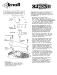
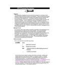
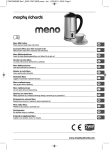
VC201 Keypad functions
Volume level
indicator for
this room only
Room power on and
volume up button
Mute button (volume
level led blinks)
Infrared signal
receiver
(VC201i only)
Room power on,
volume down and
all room power off
button (hold down
button for three led
blinks)
Limited Warranty
System status led and
infrared signal confirming
led (VC201i only)
Knöll Systems warrants VC224pm and VC226pm systems sold in the USA or Canada
by authorized Knöll dealers to be free from defects in materials and workmanship.
This warranty extends for three full years from the date of purchase by the
consumer. Any products returned freight prepaid to Knöll Systems and found to be
defective by Knöll Systems within the warranty period will be repaired or replaced
at Knöll Systems option, at no charge. Knöll Systems will not be responsible for the
actual cost of installation or removal of the product, nor for any consequential or
incidental damages. Some states do not allow the exclusion or limitation of
incidental or consequential damages, so the above limitation or exclusion may not
apply to you. This warranty gives you specific legal rights. You may have additional
rights which vary from state to state. Knöll products sold outside of the USA and
Canada may be covered by warranties provided by an authorized Knöll distributor.
Please contact the distributor in the country that the Knöll product was purchased.
* DMS, Powermatch, Transformer free and Digicom
are trademarks of Knöll Systems
Printed in Canada
Knöll Systems, Richmond, BC & Point Roberts WA
C COPYRIGHT 1998-2003, Knöll Systems, All Rights Reserved
Knöll Systems
tel (604) 272-4555
fax (604) 272-5595
In America:
145 Tyee Drive
Point Roberts, WA 98281
In Canada:
11791 Machrina Way #120
Richmond, B.C. V7A 4V3
systems
VC224pm
VC226pm
Digital Four or Six Room
Stereo Volume Control System
INSTALLATION
AND OPERATION
MANUAL
Version 1.4
Congratulations and thank you for choosing the Knöll digital
stereo volume control system. This system is designed to
individually control stereo speakers in up to four or six rooms
with many advanced features. This product is a member of the
proprietary Knoll transformer-free family which are widely
regarded as the finest stereo volume controls made anywhere.
The VC224pm has four room capability and the VC226pm has
six room capability. The VC220pm has one room capability.
IR (Infrared) Outputs: The VC224pm and VC226pm feature infrared
outputs from any VC201i keypads. The signal gathered from most remote
controls can be routed to back to the source components to control various
aspects of those components (play, fast forward, change disk, change tuner
channel, etc.). To connect the VC224pm or VC226pm controller IR outputs,
simply connect the VC224pm or VC226pm IR connector to an infared
connection block's IR receiver input (without needing an IR connection block
power supply). Then connect single or dual infrared emitters to the
connection block and place the emitters on the stereo components to be
controlled at the stereo location.
Key Features:
For controller based IR control of the VC226pm, the IR inputs must be
connected to each room RJ45. The IR signal must be common ground and are
the learned signals from our RB8 remote control. The RJ45 pin 3 is ground
and pin 6 is IR+ (pin counts are from the left).
1. Transformer-free sound quality. Being
transformer-free means the best sound quality possible in all
rooms without the phase and level problems associated with
conventional volume controls.
2. Contemporary keypad styling. The VC201 keypads
feature the latest Decora styling with six led power level
indicators. Colors are white, almond and ivory and the VC201
can be ordered with internal infrared receivers (VC201i).
VC201 keypads are all single gang.
3. Individual room start mute and turn on level
adjustment. Each room can "boot-up" muted or with the
sound on. The level of each room when the sound comes on can
be installer preselected (and changed later if required) from
either a quiet position 6 (of 17 total) or a louder position 12.
4. One or two VC201 keypads can be
connected in each room. Ever need volume controls on
both ends of a great room? This feature is available on all
Knoll digital volume controls without any extra adaptors.
5. Individual room infrared remote control. Each
room can have its volume raised or lowered, sound muted or
unmuted and power on or off with the RB8 remote when a
VC201i keypad is installed in that room. The VC201i also
passes component remote control signals to the source, such
as play, skip, AM/FM, etc.
6. Any or all rooms can be controlled by an
external controller instead of a keypad. Using
the VC224 or VC226 infared inputs to each room, a common
ground IR based controller can send remote commands.
2
Operation: The Knöll digital volume control is very easy to use. It has a
total of 17 different volume settings. Volume settings affect only the
room that they are in.
After the stereo is turned on, you may or may not have sound depending on
how the system was set up during installation.
To increase the volume (in this room only), push the rocker button up.
Hold the button up continuously and the volume will increase until maximum.
To lower the volume, push the rocker button down. Hold the button down
continuously and the volume will decrease until it mutes.
At any time firmly press the center of the switch to mute the volume. To
restore the volume press the rocker button up or down.
The RB8 remote control source buttons do not work with the VC224pm and
VC226pm as they have no source selection capabilities.
If infrared emitters where installed other (source) remote controls aimed
at the VC201i keypads will control the source components.
On VC201 keypads the lower led indicates that power to the system has
been switched on. The six side leds show the relative selected volume.
When in mute (center of rocker has been pushed) one of the side leds
blinks. To restore the volume press the rocker button up or down.
On VC201i keypads the lower center led blinks red when any IR signal is
passing through it.
Note: If the stereo is on and the Knöll digital volume controller has lost
power, it defaults to position #12.
7
Cat wires from rooms with more than one VC201 are run from one VC201 to
the other then home run back to the controller.
It is very important to use a top quality RJ45 8/8
crimper tool. We strongly suggest using a cat 5
RJ45 electronic tester to verify the wire conductors.
Connection to Stereo Equipment: Remove the VC224pm orVC226pm green
four-position speaker connector labelled "INPUT". The stereo amplifier or
receiver outputs (left and right) are connected to this VC224pm or VC226pm
connector. Be very careful to observe the correct polarity. This controller
uses independent floating grounds so bridged amplifiers can be used safely.
VC224pm and VC226pm controllers are rated for
use with maximum 120 watt per channel amplifiers.
DO NOT use higher-powered amplifiers with this
product for safety reasons.
The amplifier or receiver must be rated for four ohm speaker use to work
properly with the VC224pm or VC226pm controller. Connect the controller
to the amp or receivers speaker A or speaker B terminals. Wire the VC224pm
or VC226pm connectors labelled “ROOM1", "ROOM2" etc. directly to the
correct room speakers, again strictly observing polarity.
Power Requirements: The VC224pm and VC226pm are shipped with a 12VDC
500mA (or more) power supply (supplies power to the keypads). If possible,
connect the 12vdc power supply to the switched outlet on the rear of the
amplifier or receiver. This wiring causes the VC224pm or VC226pm
controller to reset to its selectable “boot up” every time the receiver or
amplifier is turned on but when the power is off the IR section of the
VC201i will not work. If the IR is required to work all the time, then the
controller power supply must connected to an unswitched outlet.
Installer Selectable “BOOT UP”: The VC224pm and VC226pm allow the
installer to select how the volume control “boots up” in each room when the
controller first receives 12vdc power. For this feature to work, be sure to
plug the 12vdc power supply to the switched AC outlet on the rear of the
receiver or amplifier. Please note #6/12 and S/Mute labels are inverted
on zones 2, 4 and 6 on the version 1.3 board.
To always Start MUTEed make sure the shunt on the right side of the
controller room number labelled “S/MUTE” is in place. Remove this shunt and
this room starts with the music on.
To always start up in a quiet position #6 (of 17) sure the shunt on the right
side of the controller room number labelled “# 6/12” is in place. Remove this
shunt if this room is to start in the louder position #12.
To restore the boot up defaults, replace the appropriate room shunts.
6
Installation
Installing the digital volume control system should be relatively
easy. With a bit of planning, it will give trouble free service
for years.
Basic System Layout and Pre-Wiring: See “Typical Wiring Diagram” on
the centerfold page. The VC224pm and VC226pm make a noticeable “click”
sound when changing volumes. We suggest mounting it in a low voltage panel,
electrical room, closet, etc. We do not suggest connecting more than one
VC224pm or VC226pm to a single amplifier or receiver, even if it is a high
power model because a variety of power sharing problems can occur.
One or two VC201 keypads can work on a single room or zone but only one
VC201i can be connected to a single VC224pm or VC226pm room or zone.
The VC200 keypad does not work with this system.
Use the standard T568A wiring practices to run a cat 5 or cat 3 wire from
the keypad or controller to the VC224pm or Vc226pm. If more than one
keypad controls a single VC224pm or Vc226pm room, daisy chain the cat
wire from keypad to keypad. If the VC226pmi is not located next to the
stereo, run a single eight-conductor cat 3 or cat 5 wire run and four
speaker wire conductors from the stereo to the controller for the power
supply, the infrared system, future upgrades such as paging override and of
course the steeo speaker sound.
From each speaker run a home run fire rated two-conductor speaker wire
to the VC224pm or VC226pm. To save time and money, most installers run a
four-conductor speaker wire from the VC224pm or VC226pm to the closest
appropriate speaker and then run a short two-conductor speaker wire to
the other speaker. If there is more than one pair of speakers connected to
a single VC224pm or VC226pm zone, the speakers can be wired in series or
parallel whichever makes the impedance closest to 4 or 8 ohms. Do not
attempt to make the final combined speaker impedance less than 4 ohms.
Connecting VC201/VC201i keypads to VC224pm and VC226pm controllers:
Use a single cat5 wire using all eight conductors (usually run inside a wall).
Always use standard T568A Cat 5 wiring practices (shown below). Use the
correct wire pairs. Polarity is VERY important! The stereo signal is not
routed to the keypad, just the digital control signals. Signals from an
infrared receiver (if used) are routed down the same Cat 5 wire. If more
than one keypad (VC201, not VC201i) is to be connected to a VC224pm or
VC226pm controller, the wires to the keypads are paralleled. continued..
brown 8
white/brown 7
orange 6
white/blue 5
blue 4
white/orange 3
green 2
white/green 1
3
VC224pm and VC226pm typical wiring diagram
Power supply.
Connect to the
switched oulet on
the receiver or
amplifier if
possible
To have a room or zone
start with the music
on when the VC226pm
powers up, remove the
shunt labelled
S/MUTE. Otherwise
the keypad has to be
pushed or remote
touched to turn on this
room only.
Connect the
power amplifier's
speaker outputs
to the VC226pm
jack labelled
"INPUT"
Make sure proper
wire polarity is
observed.
VC226pm Cabinet
INPUT
ROOM1 ROOM2
ROOM3 ROOM4
12vdc 500mA
120 WATT
MAXIMUM
STEREO
AMPLIFIER
VC201 Keypad
4-16 OHMS
ROOM #1
IR55
Infrared connection
module to emitters
S/Mute #6/12
12VDC
#6/12 S/Mute
S/Mute #6/12
S/Mute #6/12
IR OUT
#6/12 S/Mute
Labeled wrong on version 1.3
#6/12 S/Mute
When the sound does
come on (whether or
not S/MUTE is
selected) the sound
always comes on in
position #6 (of 17
total). To make the
music start in this
room only at position
#12, remove the shunt
labelled #6/12.
ROOM5 ROOM6
Home run
four conductor
speaker wire
Home run
cat 5 wire
VC201 Keypad
One or two VC201
keypads or one
VC201i keypad can
control each rooms
stereo speakers.
Connect the one or
two VC201 or one
VC201i keypad to
the VC226pm
cabinet's correct
RJ45 8 conductor
connector using a
home run of cat 5
wire. Be sure to
use a good quality
RJ45 8/8 crimper.
Speakers
ROOM #6