1
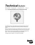
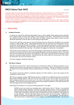
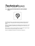
Kirby Morgan 77
Chapter 3.0
Operating Instructions
WARNING
This manual is our effort to explain the operation, maintenance and use of the Kirby Morgan helmet. We do not herein make any effort to teach the principles of diving. It is our assumption the
reader is a qualified diver. We highly recommend that all divers should train, under controlled
conditions, in the use of any model of commercial diving helmet that they have not previously
used or trained in, prior to use on the job.
3.1 Introduction
This section provides advice on how to use your Kirby
Morgan helmet. The use of these diving helmets will
vary with the type of work and environmental conditions. The basic procedures of donning and removing
these helmets will be similar for every job.
The umbilical is the diver’s lifeline to the diving
control station.
WARNING
Kirby Morgan diving helmets are not intended for use with a self contained gas
supply (scuba). There is no provision
for surface swimming once the scuba
air supply is depleted. This could lead
to suffocation or drowning, which could
be fatal.
A proper training program in a calm, clear body of
water should be undertaken. If the diver has not used
a particular Kirby Morgan helmet before, he must not
dive with the helmet without proper training.
However, divers that are familiar and trained in the
use of previous Kirby Morgan masks; i.e., KMB 8,
9, 10, 18, 28, the Navy MK. 1 Mask, Navy MK. 21
helmet, or the Navy MK. 22 mask or the SuperLite
helmets, will find that all Kirby Morgan diving helmets and masks have the breathing system controls
located in the same position. The operation of this
helmet will also be similar. The diver must be tended
at the surface at all times by a trained, qualified commercial diving tender.
3.2 Design Purpose
All Kirby Morgan diving helmets are designed for
use with an umbilical.
The umbilical is usually composed of at least a gas or
air supply hose and communication wire, assembled
with waterproof tape (and in some umbilicals wound
similar to strands in a rope) to form a single unit.
Some umbilicals also include a hose for hot water, a
pneumofathometer hose, and a strength member, such
as a cable or strong line.
It is strongly recommended that the air/gas umbilical
be married to a strength member in a manner that
allows the strength member to receive the strain.
This will help reduce the possibility of umbilical and
umbilical fitting fatigue and possible failure.
The diver must be tended at the surface at all times by a
trained, qualified commercial diving tender.
© Copyright 1970-2008 Kirby Morgan Dive Systems, Inc. All rights reserved.
Document #080626002
41
Kirby Morgan 77
The diver must be tended at the surface at all times
by a trained, qualified commercial diving tender.
Never dive without a qualified tender holding your
diving hose.
The diving control station can be at the surface, in
a diving bell, or in a submerged habitat. The diving
control station is the center of the air/gas supply, communications with the diver, and diving procedures.
The station can be as simple as a tender with a set of
“phones” (communication amplifier), or as complex
as a control van in the midst of a saturation system.
WARNING
All diving always involves the risk of
decompression sickness. Omitted decompression due to loss of gas supply or
other accidents can cause serious injury
or death. The use of the Kirby Morgan
helmets or masks cannot prevent this
type of injury.
KMDSI manufactures a complete Air Control System,
the KMACS 5™ with integrated communications
and pneumofathometer. This portable system can be
operated on either a high pressure air supply or on a
low pressure compressor. The Air Control System has
a specially designed high pressure regulator that reduces high pressure air and provides an adequate flow
to support divers to a depth of 130 fsw (40 msw)
The helmet demand regulator and side block assemblies have been designed to operate with a supply
pressure from 130 p.s.i.g. (8.8 bar) to 225 p.s.i.g.
(16 bar) over ambient pressure. This wide operating
range allows flexibility when using various gas supply systems.
WARNING
High pressure supply regulators and associated piping systems for surface supplied diving with Kirby Morgan helmets
and masks must be capable of delivering
a minimum of 3.2 acfm to the diver at
depth. Only systems that can deliver the
required gas flow should be used.
42
For maximum breathing performance it is desirable
to maintain an over bottom supply pressure in accordance with the low-pressure and high-pressure
supply tables found in Chapter 2 of this manual. With
the many different gas supply console configurations
in use, it is important to ensure that the gas supply
system used, is capable of supplying the helmet with
the necessary pressure and flow of gas to allow the
diver to work safely and efficiently.
There are also detailed checklists for the set-up and
maintenance of your helmet on the Dive Lab web site
at www.divelab.com.
3.3 First Use of Your Kirby Morgan
Diving Helmet
When you first receive your Kirby Morgan diving
helmet, carefully unpack it and examine it for any
damage that may have occurred during shipment.
Use the inspection sheet provided to ensure that no
damage has occurred. The purchaser must contact
the freight carrier and/or the KMDSI dealer if the
helmet has been damaged in shipment.
Early production of the REX 77 helmet had a much
different surface finish than what is found on current
production runs.
Earlier helmets shells and components were finished
using a combination of glass and Stainless Steel
beads; this gave a dull or flat looking surface finish.
Later shipments have a surface finish with a much
smoother and almost shiny appearance. Although the
parts are not shiny, the surface finish is very smooth.
A Scotch-Brite®, (or similar non metallic), scouring
pad will remove buildup of unwanted surface deposits on both older, and newer REX 77 helmets. It can
also be used to give the main helmet components on
newer helmets, a satin (brushed ) finish.
Be sure to complete the enclosed warranty card
and return it to KMDSI immediately. No warranty
claims will be honored without a correctly completed warranty card on file at KMDSI.
© Copyright 1970-2008 Kirby Morgan Dive Systems, Inc. All rights reserved.
Document #080626002
Kirby Morgan 77
3.4 Initial Adjustments to
Your Helmet
Before using the helmet for the first time, it must be
checked and adjusted for proper fit. There are several
adjustments that must be made to provide a more
comfortable fit when wearing the helmet.
3.4.1 Head Cushion
The fit of the helmet is primarily determined by the
layers of open cell foam that fill the head cushion
bag.
The center top/rear foam is very dense to reduce
WARNING
KMDSI must have your current address to
ensure that you receive all safety notices
and other important information concerning the helmet. Please notify KMDSI of
any change of address.
compression and spring-back. This reduces the tendency of the helmet to ride up when underwater. Do
not replace this rigid foam with a soft foam. A softer
foam is used on the sides and around the bottom of
the head cushion.
The head cushion should be adjusted for best fit.
dam opening so that the two “edges” of the neck
dam are parallel. The neck dam must be under slight
tension but must not be stretched beyond its normal
length. Trim the neck dam with the largest, sharpest
scissors available, in order to make as few cuts as
possible. There must be no jagged edges on the neck
dam or it may tear.
Trim only 1/4 inch off the neck dam at a time. When
you are done, the neck dam must be just tight enough
The diver’s head can be moved forward into the oral
nasal mask by adding layers of additional foam at the
rear of the head cushion. Do not add to much foam to
the rear of the head cushion, as this may position the
diver’s chin too far into the oral/nasal mask and create
an uncomfortable fit. The diver’s head can be moved
up or down in the helmet by decreasing or increasing
the foam pads at the top of the head cushion.
Usually, a diver with a small head will use all the foam
that comes with a new hat. A diver with a larger head
will need to remove a layer of foam in the center top
and back of the head cushion. The foam may be cut
with scissors to provide a better fit, or more foam can
be added to give a tighter fit.
The chin cushion can also be adjusted if necessary.
3.4.2 Trimming the Neck Dam
If your helmet is new, or any time you replace the
neck dam, it must be adjusted to fit you. New neck
dams are cone shaped and will probably be too tight
if not properly trimmed.
The neck dam must be trimmed to fit your neck. To
trim the neck dam, have your tender hold the neck
© Copyright 1970-2008 Kirby Morgan Dive Systems, Inc. All rights reserved.
O-ring
Neck
dam
Stepped
Ring
Split
Ring
Pull
Strap
Screw
Neck Dam components.
WARNING
Never dive with a neck dam that is too
tight. A neck dam that is too tight could
cause the diver to pass out due to pressure on the carotid artery in the neck.
This could lead to severe personal injury
or death.
Document #080626002
43
Kirby Morgan 77
so that it does not leak. This may feel a bit snug out of
the water, but should be comfortable underwater.
If you have a neoprene neck dam, it may also need to
be stretched for it to fit properly. Trim the neck dam
until it is still snug, then stretch it by sliding it over
a scuba tank and allowing it to sit overnight. If you
still cannot get the proper fit by stretching the neck
dam, it must be trimmed further. Do not trim more
than 1/4 inch at a time.
3.4.3 Adjusting the Neck Pad
Another component that controls the fit of the Kirby
Morgan helmet is the adjustable neck pad. The neck
pad, which is mounted on the locking collar, slides
back and forth along the locking collar body for
adjustment to fit different divers. Two screws and
adjustment nuts lock the neck pad plate to the locking
collar. Loosening these screws from the mount nuts
allows the neck pad to be adjusted.
CAUTION
Trimming the
neck dam.
As the neoprene
neck dam ages, it will become looser, due to a natural
breakdown of the cells. This is particularly true if
the helmet is locked in and out of a bell or saturation
system. As the neck dam becomes worn it will need
replacement to ensure that it seals properly.
Washer
Teflon
Washer
Washer
Avoid trimming neoprene neck dams too
much. Neoprene neck dams will loosen
over time as they are used and the cells of
the foam neoprene break down. If you trim
the neck dam too much it will be too loose
and will leak. Trim the neck dam until it is
snug, then stretch it before use.
The following procedure requires a diver and tender.
You do not need to have the air on to the helmet if
you do not use the neck dam ring assembly. If the
neck dam assembly is used, the diver must have air
to the helmet to breathe.
With the helmet face down on a suitable surface, pull
and turn each of the sealed pull pins until they are
locked open. Swing the locking collar/neck pad as-
Nut
Adjustment nut
Locking collar
Hinge bolt
Washer
Screw
Locking Collar components.
T-washer
Neck pad
44
© Copyright 1970-2008 Kirby Morgan Dive Systems, Inc. All rights reserved.
Document #080626002
Kirby Morgan 77
sembly out away from the base of the helmet. Slightly
loosen the screws until the neck pad can slide back
and forth. Be sure each of the head cushion snaps
are attached to their corresponding fitting inside the
helmet.
Pick up the helmet and pull the nose block device
knob out fully. Position the helmet on your head so
the oral nasal is in the proper position on your face,
covering your nose and mouth. Turn the sealed pull
pins to the locking position with the ridge on the pins
engaging the notch in the sleeve and the pins fully
retracted.
3.5.1 Pre-Dive Visual Inspection
Visually inspect the exterior and interior of the helmet.
1) Inspect the regulator cover for any damage. The
purge button must work.
2) The neck dam must not be torn or punctured, and
properly trimmed to fit.
WARNING
There must be no holes in the neck dam.
If there are any holes in the neck dam the
helmet could leak or flood. In addition,
the demand regulator will not operate
properly. Drowning could result.
Tilt your head forward so the locking collar/neck pad
assembly may be swung forward and locked up into
its closed position. The sealed pull pins must snap
into place on the locking collar.
Lift your head back up and slide the neck pad forward
until it is snug but comfortable. Mark the position of
the neck pad on the locking collar using an indelible
marker. Pull the sealed pull pins out to their unlocked
position and let the locking collar open.
3) Inspect the O-ring on the neck dam ring assembly. The O-ring must be in place, undamaged, and
lubricated.
Remove the helmet. Position the neck pad plate on the
locking collar at the marked position and tighten the
screws on each side. After the adjustment screws are
tightened, don the helmet again, tilt your head forward
and lock the locking collar/neck pad assembly. Move
your head in various positions to make sure the pad
is adjusted for comfort.
The O-ring on the neck dam ring assembly on the Kirby Morgan helmet must be
in place and in good condition. It must
be properly lubricated for smooth operation. Without a proper functioning O-ring
the helmet will leak and possibly flood.
Drowning could result.
The helmet is now adjusted for your head. It should
need no further adjustment unless another diver uses
the helmet.
4) Inspect the bent tube that supplies breathing gas
to the regulator. There must be no dents or kinks in
the assembly.
3.5 Pre Dress-In Procedure
5) Inspect the face port. It must be in good condition.
Before dressing in for a dive, inspection of the helmet
systems must be made to be sure it is in proper working order. This must be done well in advance of the
dive so any problems can be fixed without delaying
the dive. The following steps are part of the recommended daily maintenance.
WARNING
6) Be sure the communications wires are hooked up
and tested.
7) Inspect the oral/nasal mask. Make sure it is on
the regulator mount nut properly and the valve is
installed properly.
8) Inspect the sealed pull pin on each side of the helmet. They must engage and disengage properly.
9) Make sure the head cushion and chin cushion are
properly fastened inside the helmet. The chin strap
should be open as wide as possible.
© Copyright 1970-2008 Kirby Morgan Dive Systems, Inc. All rights reserved.
Document #080626002
45
Kirby Morgan 77
10) Check the screws on the port retainer . They must
be adjusted to the proper torque setting specifications
noted in Appendix 1 of this manual. Binder head
screws are used in this application for their self locking characteristics.
WARNING
All parts on Kirby Morgan diving helmets
must be adjusted to their proper torque
specifications. See Appendix 1 for a
complete listing of torque specifications
for each part. Failure to adjust parts to
the recommended specifications could
lead to helmet failure and accidents. This
could be fatal.
3.6 Preparing the Helmet for Diving
3.6.1 Clean Face Port
Thoroughly clean the face port with a soft cloth and
a mild liquid soap solution. DO NOT USE ANY
AEROSOL SPRAYS ON THE POLYCARBONATE
PORT!
3.6.2 Check Moving Parts
Check all moving parts, such as the regulator adjustment knob, the defogger control knob, emergency
(EGS) knob, and the nose block device knob and
all locking collar parts to ensure smooth and proper
operation.
3.6.3 Check Communications
Check the communications system for proper operation. Put the helmet on and talk to an assistant on the
amplifier. If you are by yourself, with the helmet off
take the helmet near the amplifier and tap on each
earphone and the microphone, listening to the taps
on the amplifier/speaker. Talk into the amplifier/
speaker feeling the vibration on each earphone and
the microphone with your fingertips. Check the fit
and tightness of the comm module mount nut.
3.6.4 One Way Valve Check
The one way valve must be tested daily, prior to
commencement of diving operations.
1) Prior to attaching (or pressuring up) the umbilical,
close the emergency valve knob, attach and pressure
up the emergency hose. Shut off the defogger control
knob and screw in the adjustment knob on the regulator all the way.
2) With the emergency hose pressurized, turn on the
emergency valve knob. If any gas escapes out the end
of the adapter, the one way valve is faulty and must
be rebuilt or replaced. A one way valve repair kit is
available to rebuild these valves (Part # 525-330).
You can test the one way valve by connecting the bailout bottle to the emergency valve and pressurizing the
sideblock. There must be no gas leakage through the one way valve.
46
© Copyright 1970-2008 Kirby Morgan Dive Systems, Inc. All rights reserved.
Document #080626002
Kirby Morgan 77
WARNING
The one way valve must be tested daily,
prior to commencement of diving operations. Failure of the one way valve could
cause serious injury or death.
3.7 Emergency Gas System (EGS)
If the diver’s main gas supply fails, the diver must
have another source of gas that will enable him to
return to the dive station or to a point where a normal gas supply can be reestablished. For this reason,
an emergency gas supply (bailout) cylinder must be
used on all dives. The bailout cylinder is normally
worn on the back using a combination backpack and
lifting harness.
WARNING
Do not dive without a diver worn Emergency Gas System. If the main gas supply
is lost, you will have nothing to breathe
and may drown.
You can also test the one way valve by attempting
to suck air through the valve. The emergency valve
must be open for this test to work properly. If you
are able to suck any air through the valve it is not
working properly.
WARNING
Never dive if the one way valve is not operating properly. If the hose or breathing
gas/air fitting breaks near the surface a
serious injury could result to the diver’s
lungs and/or eyes. In extreme cases this
could be fatal. The one way valve must be
tested daily prior to the commencement
of diving operations.
Diver donning a complete bail-out system.
Most commercial divers wear a harness (separate
from the weight belt) that is used for several purposes. The harness is fitted with large metal rings
(usually brass or stainless steel). The umbilical is
hooked into one of these rings to keep any strain off
the helmet. In addition, the rings on the harness are
used to hang tools and other equipment. Usually the
harness is also designed to provide a means of lifting
an unconscious diver from the water. This harness is
the best method of securing the emergency breathing
gas to the diver.
© Copyright 1970-2008 Kirby Morgan Dive Systems, Inc. All rights reserved.
Document #080626002
47
Kirby Morgan 77
WARNING
Never dive without attaching the umbilical to some type of harness or clip on the
diver’s body. Never allow the umbilical
to pull on the helmet directly or the diver
could suffer a neck injury.
A small tank can be mounted horizontally on the
lower rear or front, while larger tanks are usually
mounted vertically in the center back similar to a
Scuba diver’s tank. Some harness designs incorporate
a cloth enclosure into which the tank fits. The entire
tank, valve, and regulator are enclosed in fabric. This
helps to prevent snagging.
European C.E. ONLY
In European countries that have adopted C.E. certification, only C.E. certified cylinders are allowed to
be used and must have a minimum charged capacity
available to the diver of 1400 N/l (50 scf). The emergency gas supply must only be fitted with a KMDSI
first stage regulator and have a KMDSI over pressure
relief valve installed (Part # 200-017). The relief
must be adjusted to start lifting at approximately
180-200 p.s.i.g. (12.4-13.8 bar) above the regulator
intermediate setting. The purpose of the relief valve
is to allow pressure to vent off in the event the first
stage regulator develops a leak or creeps. Without a
pressure relief valve, the hose could rupture and the
emergency gas supply would be lost.
WARNING
A standard Scuba submersible pressure
gauge must be connected to the high
pressure port on the first stage so that
the diver can monitor his emergency
supply.
Use a good quality first stage for
your emergency gas supply.
The diving harness must have a provision for attaching the emergency gas supply and a place to
attach the diver’s umbilical.
When determining the size of the emergency gas
cylinder to use, several factors must be considered.
The divers depth, the length of time the diver may be
without the main gas supply, and the gas consumption rate. Regardless of the cylinder used, it should
be of sufficient volume to allow the diver to ascend
at a normal rate or transit to a point where a normal
gas supply can be reestablished.
48
The emergency air/gas tank must be fitted with a
good quality first stage regulator to reduce the pressure to less than 225 p.s.i.g. (16 bar) ambient diver
pressure. Connect the first stage hose with a set of
quick disconnecting locking sleeves to the emergency
valve assembly located on the side block.
The first stage regulator must have at least two low
pressure ports. One port is used for the connector
hose to the emergency valve and the second is used
to install an overpressure relief valve (Part #200-017).
If the first stage develops a leak, the full pressure of
the tank could be placed on the low pressure hose.
This could cause the hose to burst. The overpressure
relief valve will bleed off any leak.
© Copyright 1970-2008 Kirby Morgan Dive Systems, Inc. All rights reserved.
Document #080626002
Kirby Morgan 77
Make sure the emergency valve knob is turned off,
otherwise the emergency gas supply will be used up
without the diver’s knowledge. Once the emergency
supply hose is connected, the tank valve is turned on
to pressurize the hose. In the event of an emergency
due to a loss of the main gas supply, the emergency
valve knob located on the side block is turned on
supplying gas to the side block assembly and the
regulator.
An over-pressure relief valve must be
installed on the first stage used for the
Emergency Gas Supply.
WARNING
Never dive without an over pressure relief
valve installed on the EGS regulator (1st
stage). Without the relief valve if the EGS
regulator develops an internal leak, or
carries-away, the full pressure of the EGS
cylinder would be placed on the low-pressure EGS hose and the Emergency Valve.
This could cause the low-pressure hose
to burst resulting in the complete loss of
the EGS system.
There are risks with each method of configuring your
bail-out system. There is a risk that if you have the
bail-out bottle on and the emergency valve on the
helmet closed, that the emergency gas could be lost
if the hose or the first stage itself develops a leak.
However, KMDSI believes that this method poses
the least amount of risk for the diver.
Probably the most serious problem with any of the
other possible configurations is that the first stage will
almost certainly flood if it is not pressurized while
you are underwater.
If the regulator floods and is not promptly serviced,
it will not perform properly when you need it in an
emergency. As a diver, you always must decide how
much risk and what types of risk you are willing to
expose yourself to when you dive. It’s up to each individual to make an informed choice regarding how
to configure your bail-out system. We cannot make
this choice for you.
WARNING
Never connect the main gas supply hose
from the diving control station to the
Emergency Gas valve assembly (EGS).
If this is done there is no one way valve
protection for the diver in the event of
damage to the umbilical or related equipment. The diver could be exposed to a
serious “squeeze”. This can result in
serious personal injury or death.
Always be sure to check the pressure in your bail-out
bottle before you dive.
KMDSI strongly recommends the use of a submersible pressure gauge with every bail-out system. Not
only does this make it very easy to check your emergency gas pressure prior to diving, it also allows you,
in most cases, to periodically check the pressure in
your system while you dive. In this way, if you have
a leak, you will probably figure it out and will be able
to take appropriate action.
© Copyright 1970-2008 Kirby Morgan Dive Systems, Inc. All rights reserved.
Document #080626002
49
Kirby Morgan 77
There are several possible ways to configure your emergency gas system, although at KMDSI we only recommend one method. The configuration we recommend is as follows:
Cylinder Valve Open - EGS Valve on Helmet Closed
This is the only method that we recommend. The advantages of this method are as follows:
• You only need to open one valve to activate your emergency supply.
• There is little danger of flooding your first stage regulator and ruining it.
Possible Emergency Gas Supply Cylinder & EGS Valve Configurations
Configuration
Cylinder Valve
EGS Valve
Advantages/Disadvantages
Configuration 1
(Regulator pressurized)
On
Off
Advantages
• One valve to open
• First stage won’t flood
Disadvantages
• If hose or first stage leaks some
or all EGS gas will be lost
Configuration 2*
(No pressure in
regulator)
Off
On
Advantages
• One valve to open
• No loss of gas from cylinder
if hose leaks or regulator leaks
Disadvantages
• First stage will flood and must
be serviced after each day of
diving
Configuration 3*
(Regulator pressurized
then cylinder valve
closed)
On momentarily
then Off
Off
Advantages
• No loss of cylinder gas if
hose or regulator leaks
Disadvantages
• Two valves to open in
emergency
• Slow leak on long dive may
result in flooded 1st stage
• If dive depth exceeds pressure
in first stage, first stage will flood
Configuration 4*
Off
Off
Advantages
• No use of cylinder gas unless
emergency occurs
Disadvantages
• Regulator will flood and need
service daily
• Two valves to open in
emergency
* Requires ability to reach cylinder
valve without difficulty
50
© Copyright 1970-2008 Kirby Morgan Dive Systems, Inc. All rights reserved.
Document #080626002
Kirby Morgan 77
WARNING
Some divers, keep the EGS gas cylinder
valve shut during the dive. Their rationale
being; in the event of an emergency, they
will simply open the EGS cylinder valve
thus eliminating any EGS air/gas unknowingly being lost due to either a 1st stage
failure or EGS hose failure.
KMDSI strongly recommends never diving with the EGS cylinder valve shut.
The reasoning behind this is twofold.
First, with the EGS cylinder valve open,
gas is immediately available in the event
of topside gas interruption via the EGS
valve on the side block simply by opening it. Secondly, and most importantly,
if the EGS regulator (1st stage) is not
pressurized, during descent it is possible
that sea water will leak through the first
stage intermediate circuit and regulator,
causing failure of the EGS regulator if not
frequently serviced and resulting in possible injury or death.
You can use a quick-disconnect whip to connect the
EGS valve to the bail-out bottle. This makes dressing
the diver much easier.
© Copyright 1970-2008 Kirby Morgan Dive Systems, Inc. All rights reserved.
Document #080626002
51
Kirby Morgan 77
3.8 Setting Up to Dive
3.8.1 Flushing Out the Umbilical
Before connecting the umbilical to the helmet, the
umbilical must be flushed out to remove any dirt,
moisture, or other debris. Connect the topside umbilical end to the topside diver control console. Ensure
there is no pressure in the divers umbilical.
Carefully uncap the helmet end of the umbilical and
hold securely while pointing in a safe direction, then
slowly bring up gas pressure to approximately 25-40
p.s.i.g. (1.7-2.7 bar). Allow the gas to flow for at least
15 seconds. If it is not going to be used immediately,
the umbilical should be recapped.
WARNING
If the one way valve or the adapter is loosened this will allow breathing gas to leak
out of the breathing system. This could
also result in a loss of all pressure to the
helmet, leaving the diver with nothing to
breathe.
3.8.2 Connecting the Umbilical to
the Helmet
When you connect the hose to the helmet be sure to
use a wrench to hold the adapter, or inlet fitting, and
a second wrench to turn the swivel fitting on the hose.
If this is not done, the adapter will turn inside the one
way valve. If this happens repeatedly the threads will
wear and the valve will need to be replaced.
Connecting the umbilical to the helmet.
The connection between the hose and the helmet must
only be made up “snug”. Excessive force will deform
and ruin the adapter. A second wrench must be used
when the helmet is disconnected as well, otherwise
the adapter and/or the one way valve assembly may
become loose and fail to make a seal.
If you are using waterproof connectors for your communications, take extra care in handling these pieces.
To connect the male and female parts, align the large
pin on the male connector with the yellow mark on
the female connector. Press the two connectors together until you hear a distinct “pop”. Do not twist
the connectors. Tape the two connectors with a bit of
electrical tape to prevent them from pulling apart.
To separate the connectors remove the tape, grasp
them at the thickest part, place your thumbs against
each other, and push apart until the connectors are
disconnected.
Connecting the waterproof connectors.
Do not twist the connectors. Do not pull them apart
by pulling on the thin part of the wires.
52
© Copyright 1970-2008 Kirby Morgan Dive Systems, Inc. All rights reserved.
Document #080626002
Kirby Morgan 77
3.8.3 Opening the Breathing Gas Supply
to the Helmet
Prior to turning on the air supply for the helmet,
check to see that the free flow valve is closed and the
regulator adjustment knob is all the way in.
Slowly bring up the gas pressure to the helmet to 150
p.s.i.g. (10.2 bar). Slowly back out on the regulator
adjustment knob until a slight free flow develops,
then turn the adjustment knob in (clockwise) until
the free flow just stops.
To properly check the breathing system you must
completely don the helmet.
3.8.4 Fogging Prevention
A thin film of anti-fogging solution may be applied to
the interior of the polycarbonate face port prior to the
dive to help prevent fogging during the dive. A mild
liquid dish washing detergent, or other commercially
available anti-fogging solutions, may be applied with
a soft rag or paper towel to the interior of the port.
The diver should use a solution which has been
found satisfactory in the past. However, do not use
an aerosol spray on the polycarbonate lens. The
propellants in some aerosol dispensers cause damage
to the lens.
WARNING
A thin film of dish soap or other anti-fogging solution should be applied to the lens prior to the diver
donning the helmet.
Never use any aerosol propelled sprays
near the face port of
the any Kirby Morgan
helmet or band mask.
The propellant used
in these aerosols can
invisibly damage the polycarbonate face
port and cause it to shatter upon impact
from any strong blow. If the face port
fails underwater the helmet will flood and
drowning may result.
© Copyright 1970-2008 Kirby Morgan Dive Systems, Inc. All rights reserved.
Document #080626002
53
Kirby Morgan 77
3.8.5 Donning The Kirby Morgan Helmet
All donning procedures must be done by the diver
until he is thoroughly at home with the helmet. This
will train for familiarity. However, the tender must
be present to assist the diver and check to ensure that
the diver has properly donned his equipment. It is
impossible for the diver to see whether he is properly
dressed in once the helmet is on his head.
To dress in, the neck dam ring assembly must first be
pulled down over the diver’s head.
Be sure to loosen the chin strap inside the helmet prior
to donning the neck dam. To loosen the strap, place
your thumb on top of the rounded end of the plastic
buckle and pull down, away from the helmet.
To don the neck dam, hold the neck dam/ring assembly vertically, in front of your chest, so that the large
end of the assembly where the pull strap is mounted
is on top. The pull strap should both be facing your
chest. Lift the neck ring assembly over your head,
grasping the front and rear of the neck ring assembly.
Pull the neck dam down over your head. The neck
dam should be as low as possible on your neck.
The neck dam is always turned up against the
diver’s neck. This is very important!
WARNING
The tender must always be present to
assist the diver while dressing and whenever the diver has his helmet on his head
while he is out of the water. It is difficult
for the diver to walk while he is dressed
in and he can stumble and fall, resulting
in serious personal injury.
With the neck dam turned down, the helmet will vent
air from the neck dam causing the regulator to free
flow. This will make the helmet very uncomfortable.
The neck dam ring assembly must be oriented so the
“tongue” on the front of the neck dam ring assembly
is pointed to the front of your body, in front of and
below your chin. You should be able to look down
and see the tongue sticking out from underneath the
neck dam ring assembly when you are wearing the
assembly and it is oriented properly.
With the diver holding the helmet, the tender should
now connect the quick disconnect fittings for the
bailout supply. Open the regulator adjustment knob
and the defogger control knob for a steady flow from
both just prior to the diver dressing into the helmet.
The tender must be available to assist the diver while he is dressing into his helmet.
54
© Copyright 1970-2008 Kirby Morgan Dive Systems, Inc. All rights reserved.
Document #080626002
Kirby Morgan 77
Open the locking collar/neck pad assembly fully.
The diver inserts the tongue on the neck dam/ring assembly into the swing tongue catch. The tender must
check to see that this is properly engaged.
The locking collar must be completely open for the
diver to don the helmet.
Push the neck dam/ring up into the neck ring on the
base of the helmet .
With the helmet face down, pull the sealed pull pins
and open the locking collar/neck pad assembly fully.
Be sure the head cushion is attached to the bottom
of the helmet. Pull the nose block device knob out
all the way.
With the locking collar/neck pad assembly fully open,
lift the helmet and place it over your head. Lower the
helmet onto the back of your head first, then pivot it
forward until your face is in position against the oral
nasal mask.
Loosen the chin strap all the way. The helmet is worn
most comfortably when the chin cushion against the
diver’s chin with the chin strap outside of the chin
cushion.
The locking collar/neck pad assembly must be open
and hanging down behind your shoulders. Tighten the
chin strap so that it is comfortable under your jaw.
Now, the neck dam/ring assembly is resting directly
© Copyright 1970-2008 Kirby Morgan Dive Systems, Inc. All rights reserved.
Document #080626002
55
Kirby Morgan 77
Although the diver must be capable of donning and removing the helmet himself, the tender must ensure that
the helmet is properly secured on the diver.
under the hat on the diver’s shoulders. The diver
inserts the tongue on the neck dam/ring assembly
into the swing tongue catch on the bottom front of
the helmet.
Grasp the base of the helmet with your fingers and
push the neck dam/ring up into the neck ring on the
base of the helmet. The neck dam ring fits very snugly
in the neck ring.
The diver then tilts his head and the helmet forward
and swings the locking collar up over his shoulders.
Push the locking collar/neck pad assembly up into
position until it locks with the sealed pull pins.
Rotate the sealed pull pins into the locking position.
If you have not positioned the sealed pull pins into
the locking position, do it now with the locking
collar/neck pad assembly in place.
WARNING
Both sealed pull pins must properly click
into position on the base of the helmet.
If the pins are not engaged correctly the
neck dam/ring assembly may not seal and
the helmet could flood. The diver could
drown as a result.
56
© Copyright 1970-2008 Kirby Morgan Dive Systems, Inc. All rights reserved.
Document #080626002
Kirby Morgan 77
3.8.6 Testing the Breathing System
Test the defogger system by turning on and off the
defogger control knob. There should be no leakage
when the valve is closed. The regulator should be
adjusted by turning the adjustment knob out until a
slight steady flow starts, then back in until the flow
just stops.
is installed and the locking collar closed. When the
diver attempts to inhale, a suction on the neck dam is
formed, indicating he is achieving a good seal. The
diver must then turn the air on immediately so that
he can breathe. If the diver does not turn the air on
he will not be able to breathe, unless the neck dam is
pulled away from his neck.
WARNING
Next, the demand regulator system is checked for
proper function: breathe in and out. Inhalation and
exhalation effort should be nearly unnoticeable. Press
in on the regulator cover. This should produce a strong
burst of breathing gas.
Do not perform this test unless the diver
and his tender are stationed immediately
adjacent to the diver’s air manifold and
you are certain the air is on to the manifold. If the diver is unable to flow air to
the helmet, either through the umbilical or
the bailout, he may not be able to remove
the helmet easily.
To break the seal in this situation, the
diver must put his hand between the neck
dam and the neck, and pull the neck dam
away from the neck. A tender must be
standing by to assist the diver in removing
the helmet if needed. Suffocation could
result.
Test the breathing system to make sure that it is operating correctly.
3.8.7 Sealing Integrity Check
If there is any doubt that the helmet is sealing properly, perform the following test prior to diving.
Turn the supply gas off at the dive control system and
bleed the umbilical.
3.8.8 Adjust Regulator for Low Work Rates
At very low work rates, such as when the diver is
resting, or during in-water decompression, the diver’s
respiratory rate may be quite slow (10-15 breaths per
minute). When this occurs, the diver’s exhalations
may not be sufficient to move enough breathing gas
through the mask exhaust to adequately wash out
carbon dioxide (CO2), if the oral/nasal does not have
a good fit on the diver’s face.
In order to ensure that carbon dioxide does not accumulate in the mask, divers who are at rest underwater
should screw the regulator adjustment knob “out,” i.e.,
away from the regulator, until a slight steady flow
occurs and the regulator can be heard to hiss. This
will help to eliminate any excess carbon dioxide from
the mask. You can also open the steady flow valve
(defogger) until a slight hiss is heard.
To perform this test, the diver must have an assistant
standing by. The assistant should be in control of the
gas supply console in the event the diver needs air or
he must be ready to lend a hand. The diver must be
next to the dive control manifold so that the air may
be turned on instantly, or the diver must be ready to
run a hand between his neck and the sealing neck dam
in order to pull the neck dam away from the neck to
allow breathing.
With the neck dam ring on the diver’s head, the helmet
© Copyright 1970-2008 Kirby Morgan Dive Systems, Inc. All rights reserved.
WARNING
Excess carbon dioxide (CO2) is dangerous. Too much carbon dioxide in the
diver’s breathing system can cause the
diver to feel that he cannot breathe for
comfort. It can also cause headache,
confusion and rapid breathing. In extreme
circumstances, carbon dioxide can cause
unconsciousness. This could lead to suffocation and death.
Document #080626002
57
Kirby Morgan 77
3.9 Removing the Helmet
To remove the Kirby Morgan helmet, start by pulling
out (forward) on each sealed pull pin and turning so
each remains in the open position. Tilt your head,
and the helmet, forward and swing the locking collar
assembly back behind your shoulders.
Tilt your head upright again and push the swinging
tongue catch forward with one hand and hold it in this
position. Grasp the pull strap and pull down on it, towards your back. This will break the seal between the
neck dam/neck ring and the helmet neck ring on the
base of the helmet. Once the seal is broken the neck
ring assembly will come loose from the helmet.
With the locking collar open, you can use the pull
strap to break the seal between the neck dam ring
and the helmet ring.
Pull the nose block device knob away from your face,
loosen the chin strap, and lift the helmet off of your
head. A good tender will be prepared to help the diver
with the removal of the helmet as required.
Grab the neck ring at the front and use your fingers
to gather the neck dam away from your neck in the
front. Lift the neck dam over your head.
58
© Copyright 1970-2008 Kirby Morgan Dive Systems, Inc. All rights reserved.
Document #080626002
Kirby Morgan 77
3.10 Diving Procedures
3.10.1 Standing By to Dive
The diver may wear the neck dam ring assembly
without discomfort if he is standing by to make a
dive. However, the helmet itself must always be the
last thing put on before the diver enters the water.
Everything else must be ready to go before the diver
puts the helmet on so he won’t have to support the
weight of the helmet while out of the water.
3.10.2 Attaching the Umbilical to the
Harness
The umbilical must now be hooked to the diver’s harness by means of a suitable clip that is bound to the
umbilical. Some divers and companies prefer a quick
release clip and others prefer a clip that is screwed
together so the diver cannot easily remove it from
his harness. The securing of the umbilical keeps the
pull of the hose at the diver’s harness and not on the
helmet.
WARNING
Never dive without attaching the umbilical to some type of harness or clip on the
diver’s body. Never allow the umbilical
to pull on the helmet directly or the diver
could suffer a neck injury.
3.10.3 Diver Dons Helmet
The diver dons the helmet as per Section 3.8.5.
3.10.4 Diver Check Gas Flow Systems
The diver must check out the breathing system himself as the tender finishes dressing him. Operate the
defogger valve, the demand regulator, and the purge
button to assure yourself of proper operation before
entering the water.
3.10.5 Communications Check
The communications system, sending and receiving,
should be checked at this point.
3.10.6 Diver Ready
The diver is now ready to enter the water. He should
be assisted to the water if needed. If a welding lens
is being used, make sure it is hinged up all the way if
the diver is making a jump entry. We do not recommend jump entries. A quick overall inspection by the
tender is done and the diver is given the OK.
3.10.7 Water Entry and Descent
The tender must make sure there is a sufficient length
of umbilical clear if the diver is using a jump entry.
There must be no chance of the umbilical hanging
up when the diver jumps. Also, the defogger valve
should be turned on maintain sufficient pressure in
the helmet to prevent the possibility of water pressure
It is essential for the diver to ensure that the breathing system is working properly before he enters the water.
Note the correct attachment of the diver’s umbilical to his harness and the use of a submersible pressure gauge
for the bailout system.
© Copyright 1970-2008 Kirby Morgan Dive Systems, Inc. All rights reserved.
Document #080626002
59
Kirby Morgan 77
from inverting the helmet exhaust valve when hitting
the water.
The diver must report to the surface immediately
after the entry. It is a good policy to descend 10 or
20 FSW (3-6 MSW), pause and check the regulator
adjustment knob to ensure adjustment for the least
breathing resistance.
The purpose of this adjustment knob is to allow the
diver the ability to compensate for variations in umbilical supply pressure. This adjustment device operates by simply increasing or decreasing the amount
of spring bias tension on the demand regulator inlet
valve.
This adjustment device is not intended as a minimummaximum device. Minimum and maximum applies to
supply pressure only. The adjustment knob should be
adjusted by the diver to be at the easiest breathing
setting at all times.
Diving a KMDSI helmet or band mask with a bias
setting greater than that just necessary to keep the
demand valve from free flowing increases the work of
breathing and reduces the diver’s ability to perform
heavy work.
Then the diver checks in with the surface before
descending to the job. If a closed bell is being used,
the diver enters the water from the bell and pauses
for a short time outside the trunk until he is sure all
systems are operating properly.
During the decent the communications must be
checked again and the diver supply pressure should
be adjusted as necessary to maintain the required
over-bottom pressure. It may be necessary for the
diver to readjust the demand regulator by means of the
adjustment knob once at the work site to compensate
for the variation in umbilical supply pressure.
3.11 Emergency Procedures
3.11.1 Flooding
In the event of partial or complete flooding, the diver
may clear the helmet quickly by tilting the helmet
forward and slightly down and activating the defogger
control knob. Pressing in on the manual purge button in the center of the regulator cover will dewater
the regulator.
After clearing, cautiously check for additional flooding. If the helmet continues to take on water, return
to the diving station, swimming with the water dump
valve positioned at the lowest part of the hat: that is
with the diver’s face forward and slightly tilted down.
Keep the free flow knob on. This increases the air/gas
pressure slightly inside the hat and keeps the water
out. Any incoming water is automatically purged.
3.11.2 Inhalation Resistance
If breathing becomes difficult, adjust the demand
regulator adjustment knob, for easier breathing by
rotating the adjustment knob counter clockwise. If
the breathing does not get noticeably better, press the
purge button in the regulator cover. If a surge of gas
does not flow with this action, open the emergency
valve.
If the flow is noticeably better, immediately notify
topside that you are on emergency gas. Insure your
umbilical is clear and return to the stage or decent line.
The diver should stay in communication with topside
personnel and make preparations to abort the dive.
The console operator should check to ensure the supply pressure to the diver is at the proper pressure.
3.11.3 Gas Flow Stops
A stop of flow in the demand regulator usually indicates the main gas supply has stopped. The diver
should first open the emergency valve by turning
the knob. If there is still no flow from the demand
regulator, the defogger valve knob should be opened.
Keep in mind that if the defogger valve is left open,
the bailout bottle will drain very quickly, particularly
if the diver is deep.
Immediately notify topside, check to insure your
umbilical is clear and return to the diving station using the emergency breathing supply. Avoid making a
rapid ascent if at all possible.
Once at the surface, or inside the bell, the diver may
remove the helmet if needed. Never ditch the helmet underwater unless conditions absolutely require
that.
60
© Copyright 1970-2008 Kirby Morgan Dive Systems, Inc. All rights reserved.
Document #080626002
Kirby Morgan 77
3.11.4 Demand Regulator Free Flow
If the demand regulator free flows, turn the adjustment knob in (clockwise) until it stops. If the free
flow cannot be stopped, the dive should be aborted.
Even if there is no serious problem to the diver, the
dive should be aborted and the problem with the
regulator corrected.
Sometimes it may be necessary to tilt your head so
the regulator is face up to help stop the regulator in a
free-flow situation.
DANGER
Rapid ascent is dangerous. It can lead to
air embolism or decompression sickness.
Air/gas embolism can cause immediate
loss of consciousness and/or death.
Even on a no decompression dive, a
rapid ascent may cause decompression
sickness. A diver must only make a rapid
ascent when he is in immediate danger of
death by drowning or asphyxiation.
DANGER
Ditching the helmet underwater must be
avoided. If the diver ditches the helmet
underwater he will not be able to see.
In many instances, even if the air supply is interrupted, topside will be able to
get it back on line quickly. Do not ditch
the helmet underwater unless you are
completely out of breathing gas and it is
impossible to return to the surface due
to entanglement of your equipment or
similar circumstances.
WARNING
Never remove the diving helmet while
you are in the stage. If you fall out of the
stage with the helmet off but still attached
to your harness it may be very difficult to
swim. Drowning may result.
© Copyright 1970-2008 Kirby Morgan Dive Systems, Inc. All rights reserved.
Document #080626002
61
Kirby Morgan 77
3.12 Post Dive Procedures
3.12.1 Removing the Equipment
After the diver is well clear of the water he may
remove the helmet. If the diver is working out of a
stage he must not remove the helmet until the stage
is on deck.
by removing it from the helmet, squeezing excess
water out, and letting the head cushion hang dry or
putting it in a clothes drier on air dry only.
3.12.2 Removing the Helmet
Remove the helmet by pulling the sealed pull pins
out (forward) and turning them until they are locked
open in the extended position. Tilt your head and the
helmet forward and swing the locking collar back
behind your shoulders. You will need to pull down
on the pull strap to break the seal between the neck
dam ring and the helmet ring and to disengage the
neck ring from the swing tongue catch.
Once the neck ring is disengaged from helmet ring,
you can loosen the chin strap and then lift the helmet
off of your head. A good tender will be prepared
to help the diver with the removal of the helmet as
required.
The emergency gas supply hose may be disconnected
while the diver leaves the helmet on or while he holds
the hat after removal. The quick disconnect makes
this procedure very easy.
The tender should then unfasten the umbilical from
the harness and take the helmet from the diver and
set it aside. (Closing the locking collar/neck pad assembly onto the helmet before setting the hat down
on a rough deck will help protect the helmet neck
ring from damage). The harness and bailout bottle
is then removed.
The helmet should be rinsed with clean fresh water
following each use, then thoroughly cleaned.
WARNING
Use only the air dry setting when drying
head cushion foam in a drier. Use of a
higher setting could cause the foam to
melt or start a fire.
3.12.3 Storage of the Helmet
Between Dives
The helmet should be maintained per the daily maintenance section in Chapter 6.
If the helmet is not going to be used for a period of
time, the head cushion, should be removed. The head
cushion should be dried and replaced in the hat before
storage. The regulator adjustment knob should be
unscrewed all the way out (counterclockwise) until
the next dive. Be sure to check the communications
components and allow them to fully dry.
When the helmet is completely dry, or the diver is
ready to leave the job, the helmet should be stored in
the carrying bag to protect it.
If the head cushion becomes wet it may be dried out
62
© Copyright 1970-2008 Kirby Morgan Dive Systems, Inc. All rights reserved.
Document #080626002