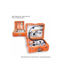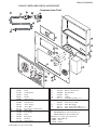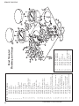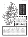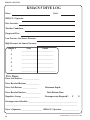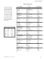
1
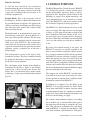
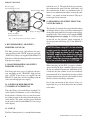
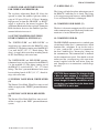
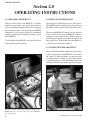
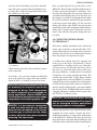
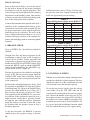
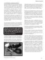
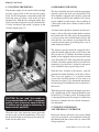
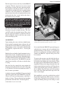
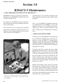
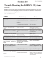
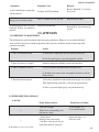
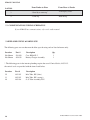
Kirby Morgan Air Control System 5
Operations and Maintenance Manual
Part # 100-075
D
IV
c
n
.
K
Y MORGA
B
N
IR
I
ES
,
YSTEMS
KMDSI
1430 Jason Way
Santa Maria, California
United States of America
Postal Code 93455
Telephone (805) 928-7772
Fax (805) 928-0342
Kirby Morgan Air Control System 5, KMACS 5,
Dive Control System-2A, DCS-2A, DCS-3 and DCS-1 are trademarks of KMDSI .
Use of these terms to describe products that are not manufactured by KMDSI is not permitted
Manual prepared by Marine Marketing and Consulting & KMDSI .
© 2003 KMDSI Document # 041112001
This page not used
Definitions of Signal Words
Used in this Manual
DANGER: This word indicates an imminently hazardous situation, which
if not avoided, will result in death or serious injury.
WARNING: This word indicates a potentially hazardous situation, which
if not avoided, could result in death or serious injury.
CAUTION: This word indicates a potentially hazardous situation, which
if not avoided, may result in minor or moderate injury. It may also be
used to alert against unsafe practices.
Warranty Information
KMDSI warrants every new mask, helmet, SCUBA regulator or air control system (KMACS) (each, a Product)
to be free from defects in workmanship for a period of ninety (90) days from the date of purchase from a KMDSI
authorized dealer. This warranty covers all metal, fiberglass, and plastic parts, but does NOT cover rubber parts,
communications components, or head cushions. Any defect of the product in workmanship or material covered by this warranty discovered within ninety (90)
days from the date of purchase must be promptly communicated in writing to the nearest authorized KMDSI
dealer or (if no such dealer in the buyer’s country) contact KMDSI directly at (805) 928-7772. No Product
returns will be accepted by KMDSI without a returned merchandise authorization (RMA) number from
KMDSI. Upon receipt of the RMA from KMDSI, the buyer should return the defective Product or part, freight
prepaid, to an authorized KMDSI dealer or the KMDSI plant, as directed by the RMA. KMDSI will repair or
replace the Product at no charge, within a reasonable time, as it deems necessary.
This warranty is null and void if:
1) The Product is not registered with KMDSI within ten (10) days of purchase, or
2) The Product has not been properly serviced and/or maintained according to KMDSI factory recommended
procedures described in the manual or Product updates have not been performed as recommended by KMDSI,
or
3) Unauthorized attachments or modifications have been made to the Product, or
4) The Product has been used for purposes other than those for which it was designed, or otherwise has been
abused, misused, or subjected to unusual conditions, or the Productís intended service has been exceeded.
EXCEPT AS SPECIFICALLY PROVIDED HEREIN, THERE ARE NO OTHER WARRANTIES,
EXPRESS OR IMPLIED, INCLUDING, BUT NOT LIMITED TO, ANY IMPLIED WARRANTIES FOR
MERCHANTABILITY OR FITNESS FOR A PARTICULAR PURPOSE. THE PRODUCT COVERED
BY THIS WARRANTY IS MARKETED AND SOLD BY KMDSI SOLELY FOR COMMERCIAL OR
INDUSTRIAL USE AND IS NOT A CONSUMER PRODUCT INTENDED FOR PERSONAL, FAMILY,
OR HOUSEHOLD USE.
In purchasing any Product subject to this warranty, the buyer agrees that its sole and exclusive remedy and
KMDSI’s entire obligation in contract, tort, or otherwise under this contract will be repair or replacement at
KMDSI’s option of the Product or any parts which KMDSI determines during the applicable warranty period are
defective in workmanship or material covered by this warranty. All exchanged parts are the property of KMDSI.
The buyer’s exclusive remedy and the KMDSI’s entire liability in contract, tort, or otherwise is the payment by
KMDSI of the buyer’s actual damages up to but not to exceed the amount paid by the buyer for the Product.
In no event shall KMDSI be liable to the buyer for indirect, special, incidental or consequential damages
(including, but not limited to, damages for lost profits, lost sales, loss of business opportunity, or for injury to
persons or property arising out of the use of the Products). Any claim or action for breach of warranty must be
commenced within one year following delivery of the Product to the buyer.
Buyer acknowledges that this warranty is the sole and exclusive warranty of the Product and that it supersedes
any and all oral or written representations and undertakings between KMDSI, its dealers, and the buyer relating
to the Products. This warranty allocates the risks of product failure between KMDSI and the buyer, which
allocation is recognized by both parties and is reflected in the price of the goods. The buyer acknowledges that
it has read this agreement, understands it, and is bound by its terms.
Table of Contents
Section
Title Page #
Section
Title Page #
1.0
General Information
1
2.3
Connecting the Air Supply 8
1.1
Definitions 1
2.4
Connecting Diver’s Hoses 9
1.2
Design Purpose 2
2.5
Pre-Dive Checklist 10
1.3
Specifications 3
2.5.1 Testing the L.P. Supply 10
1.4
General Description 3
2.5.2 Testing Communications
11
1.4.1 Breathing Air Sub System 4
2.5.3 Testing the Pneumo 12
1.4.2 Principle Operating Features
4
2.6
Preparing the Diver 12
1. Dive Control Panel 4
2.7
Dive Supervisor and KMACS Operator
12
2. Red Diver Depth Gauge 4
2.8
Descent 13
3. Umbilical Pressure Gauge 4
2.9
Diver at Depth 14
4. White Diver Depth Gauge 4
2.10
Changing out High Pressure Cylinders
14
5. Blue Air Supply Flow Indicator Line
4
2.11
Procedures During the Diver’s Ascent
14
6. Orange Air Supply Flow Indicator Line
5
2.12
Decompression 15
7. Low Pressure Inlet Fitting 5
2.13
Completion of Diving Operations 15
8. Blue Breathing Air Supply Gauge
6
3.0
Maintenance 16
9. Orange Breathing Air Supply Gauge
6
3.1
Recommended Maintenance
16
10. High Pressure Cylinder Yokes
6
3.2
Replacing the Battery 16
11. Bottom of Case 6
4.0
Troubleshooting 12. Air Supply Selector Valve Handle
6
13. Regulator Adjustment Knob
6
4.1
General 17
14. Outlet Manifold 7
4.2
No Communications 17
15. Pneumo Valve Handle, White Diver
7
4.3
No Pneumo Reading 18
16. Pneumo Valve Handle, Red Diver
7
4.4
No Air to the Diver 18
17
17. O-Ring Seal
7
5.0 Appendix 19
18. Communicator Panel
7
5.1
Emergency Procedures 19
19. Communicator
7
5.2
Diver Line Pull Signals
19
2.0
Operating Instructions 8
5.3
Communications Wiring Schematics
20
2.1
Unpacking the KMACS 5
8
5.4
Exploded Views & Parts Listz
20
2.2
First Use of KMACS 5
8
5.5 Dive Log Master Sheet
24
Kirby Morgan Air Control System 5
with no communications.
Kirby Morgan Air Control System 5 with communications.
KMACS 5 MANUAL
Section 1.0
GENERAL INFORMATION
1.1 DEFINITIONS
The following terms may be unfamiliar to the reader.
They are defined as they relate to this manual and
diving. All parts locations are referenced by LETTER
on the diagram, Figure 5, Page 8.
KMACS 5 : Kirby Morgan Air Control System
5. The Trademark name of the device this manual
describes. The KMACS 5 contains all of the
components necessary to properly control and monitor
surface supplied air dives. Included in the KMACS 5
is a two-way voice communicator for talking between
the KMACS 5 operator and the diver(s), or diver-todiver. The communicator operates in both the two
wire and four wire mode. The KMACS 5 will supply
plenty of air for two surface supplied divers.
Scuba: Self contained underwater breathing apparatus.
SSAir Diving: Surface Supplied Air Diving. Diving
operation where the diver is supplied breathing air by
way of a hose which is part of the diver’s umbilical
from the surface. Usually the source of the breathing
air is a compressor, but compressed air tanks on the
surface can also be used.
Diver’s Umbilical: Several components run together
from the KMACS 5, (Dive Control System 2A) to the
diver. These components are joined together, usually
by tape, forming the umbilical. The most common
components used in the diver’s umbilical are: (A)
a hose through which the breathing air flows to the
diver; (B) a multiconductor wire for communications
transmission; (C) another (smaller) hose which is used
to show the diver’s depth on the pneumofathometer
(see below); (4) a strong line used as a strength member to prevent strain on the other components of the
umbilical. The umbilical should be taped every 10 feet
with colored tape to indicate the length of the hose.
© 2003 KMDSI Document # 041112001
High Pressure (H.P.) Hose: A flexible hose designed to carry a working pressure of gas (or air) of
more than 300 pounds (20.7 bars) per square inch.
The rated working pressure is usually indicated on
the hose and must not be exceeded. The working
pressure of the high pressure hose on the KMACS
5 is 5000 psi (345 bars).
Whip: A hose complete with fittings at each end for
use in hooking up two pieces of deck equipment for
gas (or air) flow. For instances, the hoses and fittings
used to connect the KMACS 5 to the high pressure
tanks are called “high pressure whips.”
H.P.: High pressure. Usually any pressure over 300
psi. (20.7 bars).
L.P.: Low pressure. Usually any pressure under
300 psi. (20.7 bars).
Pneumofathometer: (pronounced “new-mo-fathometer”) This device measures the diver’s depth.
A small hose, which is part of the diver’s umbilical
runs from the KMACS 5 to the diver. The hose is
open at the diver’s end and attaches with a fitting to
a gauge at the KMACS 5. The gauge is calibrated
in feet and meters of sea water. A valve is attached
between the hose and the gauge so the operator can
use a small amount of breathing air to purge water
from the small hose. When the valve is shut off,
excess air bubbles out of the hose at the diver’s end,
and the air left in the hose will be at a pressure equal
to the pressure of the water column. This is the exact
depth of the diver.
Pneumo: Short for pneumofathometer. Used such
as “pneumo-gauge,” “pneumo -valve”, “pneumohose”, to describe the parts that make up the pneumofathometer subsystem.
Dressed-in: A commercial diver’s suit was originally called a “dress.” Although the name changed
KMACS 5 MANUAL
to “suit” the term “dressed-in” has remained to
describe putting the suit on. A diver who is “dressedin” has a suit on. The term is also used to describe
a diver who, in addition to his suit, has more, or all
of his/her equipment on.
Bailout Bottle: This is the emergency tank of
breathing gas. “Bailout” which is the familiar term
for parachuting from an airplane, also applies to the
shallow water diver who ditches part of his diving
gear and swims to the surface. The “bailout” bottle
term came from this use.
The bailout bottle is an independent air source connected directly to the diver’s mask or helmet via a
first stage scuba regulator and hose. The first stage
regulator must be equipped with an overpressure
relief valve (Part #200-015). The overpressure
relief valve will vent pressure in the event of a first
stage leak and prevent the low pressure hose from
rupturing, causing a complete loss of the diver’s
bailout supply.
The bailout bottle is worn on the diver’s back,
mounted to a harness. The diver’s umbilical should
be attached to this harness to prevent a direct pull
on the diver’s mask or helmet.
The size/volume of the bailout bottle should be
determined by the diver’s depth, or the distance
required for a direct ascent to the surface. For
deeper dives, or penetration dives inside wrecks
or pipelines, a larger capacity bailout bottle should
be used.
1.2 DESIGN PURPOSE
The Kirby Morgan Dive Control System 5 (KMACS
5) is designed to provide a central control center
for the operator/dive supervisor during a surfacesupplied air dive. Provisions for the control of the
breathing air supply, diver depth monitoring, and
voice communications are all located on a simple
panel. The KMACS 5 is a full service control system
for all Surface Supplied Air diving operations.
The KMACS 5 is fitted with shut off valves on the
diver’s air supply. The shut off valves are designed
to allow air to be shut off on either or both of the
diver’s umbilicals. When the handles of the valves
are vertical the valves are open and air is flowing to
the divers. When the valve handles are horizontal the
valves are shut and the air to the divers umbilicals
is off.
By having total control located at one panel, the
KMACS 5 operator can rapidly respond to the
diver’s needs without leaving the control station.
In a standard commercial SSAir diving operation
the KMACS 5 provides a backup air supply system
which the operator can activate in the event of the
main air supply failure (such as compressor malfunction). This can be accomplished without leaving the
control panel, which allows the operator to inform
the diver and continuously monitor umbilical supply
pressure and depth at the same time.
The compact size of the KMACS 5 usually makes
it possible to locate it at the water entry site, allowing the operator to tend the diver’s umbilical while
maintaining control of the KMACS 5.
In addition to its compact size, the ability of the
KMACS 5 to use high pressure air allows SSAir
diving from small boats or remote locations where
transportation and setup of a compressor would be
impractical. Two or more standard scuba bottles can
be used as the breathing air supply.
Fig. 1 Divers with all of the gear they need to dive.
For example, when commercial divers are working
on an offshore rig, a common SSAir diving job is
the inspection and cleaning of a propeller on a crew
boat. This job can be performed easily and simply
with the KMACS 5, a couple of scuba bottles, a full
face mask or helmet, and an umbilical. Transporta© 2003 KMDSI Document # 041112001
KMACS 5 MANUAL
tion to the job site is simple and a large surface
support vessel is not needed. At the dive site, full
communications, backup breathing supply, pressure
readouts, and depth monitoring are provided by the
KMACS 5.
This is one of many situations where the KMACS 5
can be used to provide the safe and efficient operation of SSAir diving.
1.3 SPECIFICATIONS
Use: For SSAir diving only. Pure oxygen MUST
NOT be used. Compressed air from high pressure
tanks (scuba or other types of compressed air tanks),
or from a compressor should be the only supply to
the KMACS 5
CAUTION: Pure oxygen is a potential fire
hazard, its use can lead to explosion of
the KMACS 5. Pure oxygen also presents a
physiological hazard to the diver.
Outer Dimensions: Length = 21 inches
Width = 10 1/2 inches
Height= 17 1/2 inches
Weight: 54 pounds. (24.5 kilos)
Shipping Weight: 60 pounds. (27 kilos)
Recommended Maximum Dive Support Depth:
130 fsw (feet of sea water) (40 meters).
CAUTION: Decompression and other human
limits must be observed. Decompression
diving should not be conducted with the
KMACS 5 unless a properly equipped
recompression chamber facility with
oxygen is immediately available at the
dive site. In-water decompression is not
recommended.
High Pressure Supply Pressure Maximum: 4500
pounds per square inch. (300 bars)
Low Pressure Supply Pressure Maximum: 225
pounds per square inch. (15.5 bars)
© 2003 KMDSI Document # 041112001
CAUTION: Although the high pressure
gauges on the KMACS 5 are rated to 5000
psi (345 bars), this is a safety precaution
only. The regulator on the KMACS 5 is not
designed to operate at pressures greater
than 4500 psi (300 bars).
Umbilical Pressure Range: 115-225 pounds per
square inch. (8-15.5 bars)
Regulator Output: 40 SCFM at 2500 psi (172 bars)
supply pressure with 150 psi (10.3 bars) delivery
pressure.
Relief Valve: Set at 300 psi (20.7 bars).
Pneumofathometer Range: 0-250 FSW (feet of
sea water) (0-76 meters).
Communicator: 4 wire system. Can also be used
in 2 wire mode.
Battery Type: Rechargeable, 12 volt system.
Battery Performance: 20 hours of continuous use
between charges in 4 wire mode.
Charger: Will accept external 12 volt source.
Communicator Power Output: 8 watts.
Communicator Frequency Response: 600 to
12,000 HZ.
Remote Operation Capability: Yes, with optional
unit.
Direct Recording Capability: Yes.
1.4 GENERAL
DESCRIPTION
Only equipment certified and tested according to EN
250/E DIN 58 642 may be used with the KMACS
5 when conducting diving operations in European
EC compliant countries.
The KMACS 5 components are housed in a durable
polyethylene case. However, caution should be used
in transporting the KMACS 5. Rough handling will
rarely cause damage to the case, but it is possible
to damage the calibrated pneumo gauges and/or
KMACS 5 MANUAL
the electronic components. The KMACS 5 should
be treated as you would any expensive life support
equipment.
1.4.1 BREATHING AIR
SUBSYSTEM
The diver’s breathing air subsystem starts with the
supply tank yokes (K) and connects to the diver’s
supply manifold. The high pressure hoses with the
yokes are stored for transit by connecting them to
the posts on the panel inside the lid of the KMACS
5. The knurled knobs on the yokes should be tightened until just snug. Excessive force should not be
applied.
1.4.2 PRINCIPLE
OPERATING FEATURES
l. DIVE CONTROL PANEL (A)
The panel is the main frame to which the functional
components are mounted. In addition, the component names and some instructions are on the panel.
The blue and orange lines (K, Q) on the panel
represent the flow paths of supply air from the two
high pressure hoses/yokes (S).
2. RED DIVER DEPTH GAUGE (C)
(PNEUMOFATHOMETER)
This gauge indicates the “red” diver depth. The red
diver pneumo valve knob (D), is turned to supply a
small volume of air to the small pneumo hose that
is part of the diver’s umbilical. The gauge reads
the pressure of the air in the pneumo hose. This
pressure, measured in feet (or meters) of sea water,
equals the water pressure at the diver’s depth.
3. UMBILICAL PRESSURE GAUGE (B)
This gauge (B) is connected to the low pressure air
supply system that supplies both umbilical fittings.
It indicates the breathing air pressure that is in both
the “red” and “white” diver umbilicals. When the air
supply is from high pressure tanks (such as scuba
tanks) the umbilical hose pressure can be varied by
turning the regulator adjustment knob (H)
4. WHITE DIVER DEPTH GAUGE (P)
(PNEUMOFATHOMETER)
This gauge indicates the “white” diver depth. The
white diver pneumo valve knob (O), is turned to
supply a small volume of air to the small pneumohose that is part of the diver’s umbilical. The gauge
reads the pressure of the air in the pneumo-hose. This
pressure, measured in feet (or meters) of sea water,
equals the water pressure at the diver’s depth.
5. BLUE AIR SUPPLY FLOW INDICATOR
LINE
The “BLUE” air supply flow indicator line (Q) indicates the flow path of breathing air from entry into
the KMACS 5 to exit to the diver’s umbilical(s) at
the fittings on the manifold (G). There are two high
pressure whips which are color coded BLUE and
ORANGE.
Starting from the high pressure air tank, the BLUE
air supply flows through the whip into the KMACS 5.
Following the BLUE flow indicator line (Q) it shows
the flow to the BLUE Breathing Air Supply Pressure
Gauge (M), then to the Breathing Air Supply Selector Valve which is controlled by the Breathing Air
Selector Valve Handle (I). The Selector Handle (I)
must be turned all the way “UP” until it stops for the
BLUE supply. This places the selector valve handle
in line with the flow path indicating the “BLUE” air
supply (Q). The ORANGE supply is off when the
Selector Handle is in the up position.
CAUTION: When using H.P. air, the selector
handle must be turned up until it stops for
BLUE supply or down until it stops for Orange
supply. Never allow the selector handle to
stay in the marked “H.P. OFF ZONE”. Both
high pressure air supplies are off in the
yellow striped H.P. OFF ZONE”.
After flowing through the Selector Valve the BLUE
air supply enters the Breathing Air Supply Regulator
(H) which reduces the high pressure breathing air
to an adjustable range between 115-225 pounds per
square inch (psi) (8-15.5 bars). The BLUE air supply then goes to both diver’s umbilicals through the
fittings on the manifold (G).
© 2003 KMDSI Document # 041112001
KMACS 5 MANUAL
6. ORANGE AIR SUPPLY FLOW
INDICATOR LINES
After flowing through the Selector Valve the ORANGE air supply enters the Breathing Air Supply
Regulator (H) which reduces the high pressure
breathing air to an adjustable range between l15-225
psi (8-15.5 bars). Then the ORANGE air supply goes
to both diver’s umbilicals through the fittings on the
manifold (G).
The “ORANGE” air supply flow indicator line
indicates the flow path of breathing air from entry
into the KMACS 5 to exit to the diver’s umbilical(s)
at the fittings on the manifold (G). The second high
pressure whip is color coded ORANGE.
Starting from the high pressure air tank, the ORANGE air supply flows through the whip into the
KMACS 5. Following the ORANGE flow indicator line (K) it shows the flow to the ORANGE
Breathing Air Supply Pressure Gauge (L), then
to the Breathing Air Supply Selector Valve which
is controlled by the Breathing Air Selector Valve
Handle (H). The Selector Handle must be all the
way “DOWN” until it stops for the ORANGE
supply. The BLUE supply is off when the Selector
Handle is in the down position.
7. LOW PRESSURE INLET FITTING (N)
The low pressure inlet fitting is positioned between
the connections for the two H.P. supply hoses. It
is marked by the arrow containing the words “L.P.
Supply”. Low pressure supply breathing air, usually
from a compressor (with volume tank) is supplied
through a whip (low pressure hose and fittings) that
attaches here. When the low pressure supply is the
only air source, the supply pressure will be indicated
on the umbilical pressure gauge (B). In the low pressure supply mode, the selector/valve handle will he
positioned in the H.P. OFF ZONE.
CAUTION: When using H.P. air, the selector handle must be turned up until it stops for BLUE supply
or down until it stops for ORANGE supply. Never allow the selector handle to stay in the marked “H.P.
OFF ZONE”. Both high pressure air supplies are off in the yellow striped H.P. OFF ZONE”.
A
B
C
D
E
F
G
H
I
J
K
L
M
N
O
P
Q
R
S
T
U
V
Dive Control panel
Umbilical Pressure
Red Diver Depth Gauge
Pneumo Valve Handle, Red
Divers Umbilical Breathing Hose Attachment Fittings
Pneumofathometer Hose Attachment Fittings
Outlet Manifold
Regulator Adjustment Knob
B
Breathing Air Supply Selector Valve Handle
C
Case
Orange Air Supply Flow Line
D
Orange Breathing Air Supply Gauge
Blue Breathing Air Supply Gauge
E
Low Pressure Inlet Fitting
Pneumo Valve Handle, White
F
White Diver Depth Gauge
Blue Air Supply Flow Line
Communicator
Yokes w/DIN Fittings for H.P. Cylinder Attachment G
Access door for storage compartment.
O-Ring Seal
Communicator Panel
Fig. 2
© 2003 KMDSI Document # 041112001
T
S
U
V
R
A
Q
P
O
N
H
I
J
K
L
M
KMACS 5 MANUAL
Blue Air Supply
Flow Path Indicator Line
Blue Air Supply Whip
half of the case (J). The top half of the case contains
the communicator panel with the yoke blocks and
the communicator if there are communications. If
there are no communications there are only the yoke
blocks. ( see picture in front of manual). The top is
not designed to be removed.
12. BREATHING AIR SUPPLY SELECTOR
VALVE HANDLE (I)
Orange Air Supply Whip
Orange Air Supply
Flow Path Indicator Line
Fig. 3 Air flow paths from the H.P. cylinders.
8. BLUE BREATHING AIR SUPPLY
PRESSURE GAUGE (M)
The Blue pressure gauge (M) indicates the pressure remaining in the “BLUE” high pressure tank.
(NOTE: If two divers are supplied by the KMACS 5
both divers will be breathing from the same selected
high pressure supply).
9. ORANGE BREATHING AIR SUPPLY
PRESSURE GAUGE (L)
The Orange pressure gauge (L) indicates the pressure remaining in the “ORANGE” high pressure
tank. (NOTE: If two divers are supplied by the
KMACS 5, both divers will be breathing from the
same selected high pressure supply).
10. YOKES FOR HIGH PRESSURE
CYLINDER ATTACHMENT (S)
This handle (I) controls the two position Breathing
Air Supply Selector Valve and allows uninterrupted
diving operations while full air supply tanks replace
expended tanks. The selector valve controls ONLY
the high pressure air supply. It is NOT possible
to shut off any low pressure supply connected to
the low pressure inlet fitting (N), at the KMACS 5
itself.
CAUTION: When using H.P. air, the selector
handle must be turned up until it stops
for BLUE supply or down until it stops for
ORANGE supply. Never allow the selector
handle to stay in the marked “H.P. OFF
ZONE”. Both high pressure air supplies are
off in the yellow striped H.P. OFF ZONE”.
When changing out the H.P. air supply cylinders,
always observe the diver’s umbilical pressure gauge
(B) for any sudden fall in pressure. Should this occur,
it indicates that the cylinder in use has mistakenly
been turned off. If so, immediately turn the cylinder
back on and move the selector valve handle to select
the full cylinder and change out bottles.
Due to the construction of the selector valve, it is
impossible for gas to back-flow from one cylinder
to the other.
The yoke fittings (S) provided have standard U.S.
scuba cylinder attachments as well as Din Fittings.
Each yoke has a bleeder valve to vent the remainder of the pressure in the whip when changing out
scuba bottles. The yokes attach to posts mounted
on the panel in the lid of the KMACS 5 for storage
and transport.
11. CASE (J)
The Dive Control panel (A) is attached to the bottom
© 2003 KMDSI Document # 041112001
KMACS 5 MANUAL
13. REGULATOR ADJUSTMENT KNOB
FOR UMBILICAL PRESSURE (H)
The regulator Adjustment Knob (H) allows the
operator to adjust the umbilical pressure within a
range of 115 psi to 225 psi (8-15.5 bars). Incoming
high pressure air from the ‘ORANGE” or “BLUE”
supply is reduced by the internal regulator. The
Adjustment Knob controls the regulator. Turning the
Knob clockwise decreases the umbilical pressure;
counterclockwise increases it.
14. OUTLET MANIFOLD INCLUDING
DIVER’S UMBILICAL FITTINGS (G)
The “WHITE DIVER” and “RED DIVER” air
supply hoses are connected to the KMACS 5 at the
manifold (G). The fittings coming out of the KMACS
5 are male #6 JIC (3/8”, 37°) flared fittings. The
diver’s air supply hoses must have matching female
#6 JIC flared fittings with swivel nuts.
The “WHITE DIVER” and “RED DIVER” pneumofathometer hoses are also connected to the KMACS
5 at the manifold (G). The fittings coming out of
the KMACS 5 are male #4 JIC ( 1/4”, 37°) flared
fittings. The diver’s pneumofathometer hoses must
have matching female #4 JIC (1/4”, 37°) flared fittings with swivel nuts.
15. PNEUMO VALVE KNOB, WHITE DIVER
(O)
The Pneumo Valve Knob, White Diver turns on and
off the air supply to the “WHITE” pneumofathometer
system.
17. O-RING SEAL (U)
The O-ring seal helps keep dust and moisture out of
the KMACS 5 when the case is closed. The O-ring
seal is not pressure proof, however, and the KMACS
5 case will flood if the box is submerged.
18. COMMUNICATOR PANEL (V)
The diver’s electronic communicator (R) is attached
to the communicator panel. The battery for the communicator is located behind this panel.
19. COMMUNICATOR (R)
The MK3-KMDSI communicator is a standard open
circuit/round robin diver’s communicator, which
functions like a telephone. It can also be used as
a 2 wire, “push-to-talk” system. It is connected to
the diver’s umbilicals by “banana plug” fittings on
the communicator. The communicator is mounted
on the communicator panel. You should read and
understand the accompanying radio operations
manual supplied with the unit before using the
unit. Improper use or connections could damage
the radio.
CAUTION: Never connect the charger during
a dive or when anyone is in contact with
connected equipment. Although electrical
shock danger is remote, connection of the
recharging cord should only be done when
the KMACS 5 is not in use.
16. PNEUMO VALVE KNOB, RED DIVER
(D)
The Pneumo Valve Knob, Red Diver turns on and
off the air supply to the “RED” pneumofathometer
system.
© 2003 KMDSI Document # 041112001
KMACS 5 MANUAL
Section 2.0
OPERATING INSTRUCTIONS
2.1 UNPACKING THE KMACS 5
2.2 FIRST USE OF THE KMACS 5
When you first receive your KMACS 5, carefully
unpack it and examine it for any damage that may
have occurred during shipment. Be sure to complete
the enclosed warranty card and return it to KMDSI
immediately. No warranty claims will be honored
without a satisfactorily completed warranty card on
file at KMDSI.
Place the Dive Control System on a firm surface.
The KMDSI logo should be right side up. Release
the latches and lift up the lid to expose the panels.
Visually check the KMACS 5 to ensure that it has
not been damaged in transport.
When using the KMACS 5 aboard a vessel subject to
waves or swell be sure to tie the KMACS 5 securely
in position so that it doesn’t fall. Thread a piece of
line through the handles and fasten the ends to fittings on the boat. Tie back the lid of the KMACS 5
as well to prevent damage or injury.
2.3 CONNECTING THE AIR SUPPLY
Loosen the knurled knobs which connect the yokes
to their storage posts in the KMACS 5 and remove
the yokes (S) from the blocks. Attach each yoke
to a high pressure cylinder as you would connect
a scuba regulator to a tank. The knobs on the yoke
should be screwed down finger tight. Do not apply
Fig. 5 Note the line which passes through the handle of the
KMACS 5 and is secured to the rail to prevent the KMACS 5
from moving about.
Fig. 6 Connecting a scuba air supply to the KMACS 5.
© 2003 KMDSI Document # 041112001
KMACS 5 MANUAL
excessive force to the knobs; air pressure from the
tanks will create a good seal. Be sure the bleed valve
on each yoke is in the closed position. Do not turn
the cylinders on at this time.
Prior to connecting the low pressure hose to the
KMACS 5, the deck whip should be flushed with air
to make sure no foreign matter is in the hose. Connect the deck whip to the low pressure compressor
and while firmly holding the end of the hose start
the compressor and flow air through the deck whip
for at least one minute. Attach the low pressure hose
to the low pressure inlet fitting (N) and screw the
fitting down finger tight. While using one wrench
to hold the low pressure inlet fitting tighten the hose
fitting with a second wrench. Do not use excessive
force as this will only damage the fitting and cause
it to leak.
2.4 CONNECTING DIVER’S HOSES
TO THE KMACS 5
Each diver’s umbilical should be color coded with
plastic tape to identify each individual hose. This
action will not only serve to make it easier to connect
the hoses, but will also serve to differentiate between
hoses for purposes of inspection or repair.
Fig. 7 Always use the right size wrench to connect the hoses
to the KMACS 5.
Check the function of the selector handle to ensure
correct operation.
If available, a low pressure compressor should be
used as the primary air supply and scuba cylinders
should be used as a backup, or reserve air source.
CAUTION: Low pressure compressors used
for breathing air should be specifically
designed for diving. Paint compressors
or similar equipment are unacceptable for
diving applications. (Contact KMDSI for a
list of equipment manufacturers who supply
compressors with breathing quality air).
DANGER: If a low pressure compressor
is used, the intake must be at a sufficient
distance from and upwind of the exhaust.
If exhaust gas is sucked into the intake,
the diver will suffer from carbon monoxide
poisoning. This can be fatal.
© 2003 KMDSI Document # 041112001
A standby diver should always be equipped and
ready to go to the diver’s aid whenever a surface
supplied diver is working in the water. Generally,
it is not necessary for more than one diver to be in
the water at a given time when using surface supplied gear. However, a standby diver is considered
essential for safe, surface supplied operations. The
standby diver can be either a scuba diver or another
hose supplied diver since the KMACS 5 provides
enough air for two hose supplied divers. In contaminated water diving operations, however, both divers
must be equally equipped with a vulcanized rubber
dry suit, dry gloves, and Kirby Morgan dive helmet
equipped with either a double exhaust system or the
new TriValve™ exhaust system.
CAUTION: Contaminated water diving
operations are very hazardous. They should
not be attempted without specialized
training, procedures, and equipment.
Remove the protective caps from the outlets of the
manifold (G) on the console. Connect the diver’s
umbilical hose fittings (air supply hose and pneumo)
to the KMACS 5. Remove the end caps from the
hoses themselves and while firmly holding the end
of the hose, blow out the lines before connecting the
KMACS 5 MANUAL
hoses to the mask or helmet, (refer to the manual
for the mask or helmet for the proper connection
procedures for your life support equipment). This
action will prevent any foreign matter from entering
the helmet or mask breathing system. Once the hose
is blown out, immediately connect the fitting on the
hose to the fitting on the mask or helmet.
Connect the communications portion of the diver’s
umbilical to the communications fittings on the
communicator and to the mask or helmet. Be sure
the proper connection is made with the right communications line for each diver. The wires in the
diver’s umbilical should be marked so it is easy to
identify which plug connects to the earphone terminals and which plug connects to the microphone
terminals.
2.5 PRE-DIVE CHECK
Prior to EVERY dive, the following should be
checked:
With the free flow and demand regulator on the
mask/helmet(s) shut off, turn on the air supply at
each of the air cylinders. During operation with
scuba bottles as the main supply, the selector valve
handle must be FULLY up or FULLY down. Fully
up turns the “BLUE” supply on and the “ORANGE”
supply off. Fully down turns the “ORANGE” supply on and the “BLUE” supply off.
Note the air pressure in each cylinder by reading the
gauges (L,M). The low pressure supply should be
switched “OFF” at the source at this time. A check
valve in the low pressure system prevents back flow
to the compressor.
Both cylinders should be full prior to diving. Load
the regulator on the KMACS 5 using the regulator
adjustment knob (H). Observe the umbilical hose
pressure (B) which should be set at 150 psi (10.3
bars) over top side pressure, or 165 psi (11.5 bars)
The regulator used in the KMACS 5 is a non-venting regulator. If the regulator has been left set at a
higher pressure setting than is presently desired,
the operator must turn the regulator adjustment
knob (H) clockwise and vent air from the system
by bleeding either the pneumo system or diver’s
breathing apparatus.
umbilical pressure is always 150 psi (10.3 bars) over
the pressure at the diver’s depth. Consult the table
below for approximate pressure settings.
TABLE 1
Suggested Regulator settings for the KMACS 5
Depth - fsw
Pressure
Optimal
Minimum
0’
14.7 psia 150 psig 150 psig
33’
29.4 psia 165 psig 150 psig
66’
44.1 psia 180 psig 150 psig
99’
58.8 psia 195 psig 160 psig
132’ 73.5 psia 210 psig 175 psig
165’ 88.2 psia 225 psig 190 psig
198’ 102.9 psia 225 psig 205 psig
TABLE 1, Metric
Suggested Regulator settings for the KMACS 5
Depth-Meters
Pressure
Optimal
Minimum
0
1 bar
10.3 bars 10.3 bars
10
2 bars
11.4 bars 10.3 bars
20
3 bars
12.4 bars 10.3 bars
30
4 bars
13.4 bars 11.0 bars
40
5 bars
14.5 bars 12.1 bars
50
6 bars
15.5 bars 13.1 bars
60
7 bars
15.5 bars 14.1 bars
2.5.1 TESTING L.P. SUPPLY
With the air on at the bottles and the communications
switched on, check the regulator function. The diver
should insert his face in the mask/helmet and take
several breaths to test the demand regulator.
To test the low pressure supply, place the selector
valve handle (I) in the “H.P. OFF” zone and the
console will be running off the low pressure supply
only. Observe the umbilical pressure gauge (B). As
the compressor cycles, the gauge will rise and fall as
the compressor’s volume tank fills and empties. The
maximum pressure for the L.P. inlet should be 225
psi. Again, check the mask/helmet function which
will also confirm the low pressure supply routing.
As the diver descends, the KMACS 5 operator
should increase the regulator setting so that the
10
© 2003 KMDSI Document # 041112001
KMACS 5 MANUAL
2.5.2 TESTING COMMUNICATIONS
Test the communications between the diver and the
KMACS 5. With the communicator (R) switched
on, turn the speaker switch to “on” and adjust the
volume to a comfortable level for both the diver
and the KMACS 5 operator. In the 2 wire mode,
the communicator functions similarly to a citizens
band radio; i.e., the KMACS 5 operator must depress the push to talk switch to speak to the diver.
In the 4 wire mode, the communicator functions
like a telephone conference call; i.e., everyone on
the line can hear and speak to everyone else. In
either mode, for the diver to talk top side, it is only
necessary for him to speak into the oral/nasal microphone in his mask or helmet. If two divers will
be working together, test the cross-talk functions
at this time as well.
To extend the life of the battery, it is recommended
that the communications be used in the 4 wire mode.
Operation as a 2 wire system uses relays inside the
unit which will cause a higher battery drain.
CAUTION: In the 2 wire mode, when the
push-to-talk switch is depressed, the
KMACS 5 operator should keep all of his
communications short (10-15 seconds) at
any one time. This allows the diver to call
for assistance if necessary.
Plug the earphone connectors on the diver’s umbilical into the earphone jacks on the communicator.
Plug the microphone connectors on the umbilical
into the microphone jacks on the communicator.
This will create a 4 wire system/round robin system.
Test the system and adjust all volume controls.
Unplug the earphone connectors on the diver’s umbilical from the communicator and reinstall them in
the connectors attached to the plugs for the microphone. This will change the communicator to a 2
wire system. Test this system and adjust volumes.
If there are no communications, recheck all of the
connections to ensure they are tight at each junction.
If the KMACS 5 has been operating in a coastal environment, look for corrosion on the top side connectors which may interfere with the communications.
If corrosion is evident, disassemble the connectors,
clean, and retest. If corrosion is heavy, replace the
top side connectors.
Substitute other masks or umbilicals to test for
failures in the microphones or umbilical. Substitute
one piece of new gear at a time to track the fault
down. If the fault is in the mask or helmet, replace
the earphones or microphones as needed.
If the fault is in the umbilical, disconnect the umbilical and carefully inspect its length for damage. Look
for obvious nicks or cuts.
If there is physical damage to the outside of the
communications wire there probably is a break on
the inside, too. Test the continuity of the wire end-to
end with a volt-ohmmeter.
Uncoil the umbilical and lay it out flat with the two
ends close to each other. Set the volt-ohmmeter to
resistance (ohms) and hold one probe to one prong
on an umbilical connector plug and touch the other
probe from the meter to the wires (or connector) at
the opposite end of the diver’s umbilical. Upon locating the other end of the same wire, the meter should
indicate zero resistance, i.e., there is a complete,
uninterrupted circuit. If touching none of the wires
at the other end of the umbilical produces a zero
reading and all readings are infinity (∼), this indicates
a complete break in the wire. If the reading is somewhere between zero and infinity, and changes as the
umbilical is moved, this indicates a partial break, and
communications will be intermittent. In either case,
a waterproof splice must be made in the wire.
Fig. 8 Preliminary testing of the umbilical with a volt-ohm
meter to check for continuity.
© 2003 KMDSI Document # 041112001
11
KMACS 5 MANUAL
2.5.3 TESTING THE PNEUMO
2.6 PREPARING THE DIVER
The pneumo supply may be tested in either the high
pressure supply mode or the low pressure supply
mode. To test the pneumo, select either mode and
pinch the open end (diver’s end) of the red diver
pneumo hose. With the hose crimped tightly shut,
slowly open the red pneumo valve (D) momentarily,
1/4 turn, and observe the needle’s response on the
red diver depth gauge (C).
The diver should be dressed in with the appropriate
exposure suit for the local water temperature. The
diver should be equipped with a harness to provide
an attachment point for his umbilical. By attaching the umbilical to the harness, the possibility of
a direct pull on the diver’s helmet or mask will be
eliminated.
A bailout bottle should be mounted on the diver’s
harness. Always dive with a bailout bottle, no matter
how shallow the dive. The danger of entanglement
is always present and a bailout bottle will give the
diver that few extra minutes to free himself in the
event he becomes hung up on fishing line, wire, or
other submerged objects.
The bailout regulator should be equipped with a
quick disconnect whip to make it easier to dress the
diver in and out. In addition, the bailout regulator
should also be equipped with an over pressure relief
valve (Part #200-015). This will permit the regulator
to bleed off and not rupture the low pressure hose
connecting it to the diver’s bailout or emergency
valve, should the first stage develop a leak.
With the hose attached to the harness, tuck the
pneumo hose under the harness at the diver’s chest.
This serves two purposes: 1) it provides instant
access in the event the pneumo is to be used as an
alternative air supply; 2) gas absorption and elimination of nitrogen is considered to occur at the diver’s
chest level.
Fig. 9 Carefully test the pneumo prior to every dive.
CAUTION: Do not “peg” the needle on
the pneumofathometer with a maximum
reading. A test of pressure equal to 50 feet
(15 meters) on the gauge is satisfactory to
ensure correct operation.
Close the valve after observing correct operation
and release the end of the pneumo hose. The gauge
needle should return to zero. Repeat the above procedure for the white diver.
12
When diving under a potential decompression situation, a depth gauge or dive computer should be worn
by the diver as a backup system. If decompression
is anticipated there must be enough air on hand for
the diver to complete the dive and the decompression obligation.
2.7 THE DIVE SUPERVISOR
AND THE KMACS 5 OPERATOR
During the diving operation, one person should
always be in charge to avoid confusion. Generally,
this should be the most senior diver, by virtue of his
diving experience.
© 2003 KMDSI Document # 041112001
KMACS 5 MANUAL
The dive supervisor may not always be the KMACS
5 operator. The dive supervisor may want or need
the freedom to direct the entire operation including the tenders and other personnel. As such, he is
responsible for making decisions regarding diving
conditions and safety. However, the KMACS 5
operator must always be an experienced diver who
understands the diver’s needs and has the diver’s
best interests always in mind.
CAUTION: The KMACS 5 operator must not
leave the dive control system unattended
while the diver is in the water. The KMACS
5 operator is directly responsible for the
diver’s safety and well being.
The diver must follow the KMACS 5 operator’s
directions in regards to depth and time. The diver
can NOT run the dive from the bottom. Thus, when
the dive supervisor himself is required to dive he
should relinquish control to the next most senior
diver remaining top side.
2.8 DESCENT
Upon entering the water, the diver should immediately recheck communications with top side and
ensure that his mask or helmet is working correctly.
When he/she is ready to descend he should notify
the KMACS 5 operator that he is, “Leaving the
surface.”
Both the diver and tender should communicate in a
normal tone of voice. It should not be necessary for
either person to shout to be heard. Although the quality of the communications will usually be excellent,
not all divers speak clearly. The KMACS 5 operator
should listen carefully at all times to what the diver
is saying.
Once the diver has entered the water, monitor his
descent rate using the pneumo valve (D,O) and gauge
(C,P). The diver’s descent rate should not exceed 75
feet (23 meters) per minute.
As the diver descends, the KMACS 5 operator should
adjust the regulator (H) on the KMACS 5 to provide
150 psi (10.3 bars) over the pressure at the diver’s
depth at all times. This provides the best breathing
performance from the diver’s demand regulator.
© 2003 KMDSI Document # 041112001
Fig. 10 KMACS 5 operator taking a reading with the
pneumo knob. The knob should be turned very slowly.
It is essential that the KMACS 5 operator keep pace
with the diver’s descent and not lag behind in his
depth monitoring. If this occurs, it is possible for
the diver to exceed his maximum planned depth
without the KMACS 5 operator being aware this
has occurred.
To operate the pneumo, turn the knob for the appropriate diver, counter clockwise, until the indicator needle on the depth gauge starts moving. When
the depth gauge for the individual diver indicates a
depth that is known to be deeper than the diver, the
knob is turned clockwise until it is off. The indicator
needle on the depth gauge will move shallower as
the air bubbles leave the open end of the pneumo
hose at the diver. When the needle stops, that is the
diver’s actual depth.
Most umbilicals are made up with the diver end of
the pneumo hose having about two feet (.6 meters)
of loose hose. The diver can use this hose as an air
supply for inflating lift bags or for taking an exact
13
KMACS 5 MANUAL
reading of the bottom depth. In an emergency, the
pneumo air can be used as a breathing air supply
for a diver. The diver tells the KMACS 5 operator
to “Turn on the pneumo-air...”, then inserts the hose
into the mask or helmet. When using the pneumo in
this mode the air pressure should be regulated by
the KMACS 5 operator to be slightly greater than
the diver’s depth. For example, if the diver is at 100
feet (30 meters), the pneumo should be opened until
the gauge reads a depth of 110 feet (33 meters), so
that a positive pressure exists.
The diver should practice using the pneumo as an
alternative air source under controlled conditions in
shallow water. The pneumo hose should be bubbling
when it is inserted in the diver’s mask, otherwise the
diver will receive a blast of water when the pneumo
is first turned on.
2.9 DIVER AT DEPTH
Once the diver reaches the bottom, or his maximum planned depth, the diver should inform the
KMACS 5 operator that he is, “On the bottom.” At
this time, the KMACS 5 operator should ensure that
he gets an accurate depth reading. The KMACS 5
operator should inform the diver that he is “Taking a
pneumo...”, when he opens the pneumo purge valve.
The diver should observe the end of the pneumo
hose and immediately inform top side that, “He has
bubbles...”. Once the diver has a flow of bubbles at
the end of the hose, the pneumo valve (D,O) should
be closed immediately.
Should the diver move deeper at any time during
his dive he must inform the KMACS 5 operator
and another pneumo should be taken for a new
maximum depth reading. If the KMACS 5 operator
knows that the diver is moving over an uneven bottom he should periodically take additional pneumo
readings to ensure that the diver has not accidentally
gone deeper and neglected to notify top side. Keep
in mind, however, that every pneumo reading does
use some air. If high pressure air is the air source
and the dive is deep, or the diver is working hard,
pneumo readings should be taken as sparingly as
possible.
14
2.10 CHANGING OUT HIGH PRESSURE
CYLINDERS
The KMACS 5 operator should continuously monitor the diver’s air supply at the two high pressure
gauges (L,M) when diving with high pressure air as
the primary supply. When the initial supply source
pressure drops to between 300 and 500 psi (20.7 and
34.5 bars), depending upon depth, the diver should
be switched over to the second air source using the
selector valve handle (I). While the diver is breathing
off the secondary source a fresh cylinder should be
put on line immediately.
To change out high pressure cylinders, first close
the cylinder valve on the tank which is low. Once
the valve is closed, open the bleeder valve on the
yoke (S) and allow the pressure to bleed from the
line. The high pressure whips are color coded to help
the KMACS 5 operator to ensure he is selecting the
correct one. Always observe the umbilical pressure
gauge (B) carefully during this procedure. If the
KMACS 5 operator is not careful he may accidentally turn off the high pressure cylinder supplying
the diver’s breathing air. If the umbilical pressure
gauge (B) needle starts to “fall”, turn the cylinder
back on immediately and double check to ensure
the correct cylinder is being changed.
When the high pressure whip is empty, unscrew the
knurled knob on the yoke (S) and attach the yoke
to a fresh cylinder. Tighten the yoke knob finger
tight, close the bleeder valve, and slowly open the
cylinder tank valve. Read the new pressure on the
appropriate gauge (L,M).
2.11 PROCEDURES DURING THE
DIVER’S ASCENT
At the end of the dive, the diver should prepare
to leave bottom upon orders from the KMACS 5
operator. The KMACS 5 operator must carefully
note the diver’s depth and time on the dive log. The
KMACS 5 operator is responsible for monitoring the
diver’s ascent rate which should not exceed 60 feet
(18 meters) per minute, or slower if a dive computer
is being used to monitor decompression/no decompression status. The diver should not leave the bottom until he is instructed to do so by the KMACS 5
operator. At the start of the diver’s ascent he should
© 2003 KMDSI Document # 041112001
KMACS 5 MANUAL
inform top side that he is, “Leaving the bottom.” The
KMACS 5 operator should carefully note the time in
the dive log. The KMACS 5 operator must monitor
the diver’s rate of ascent carefully, observing his
watch and the pneumo gauge (C,P) . There is no need
to pneumo the diver as he ascends because the air in
the pneumo hose will automatically expand and vent
the hose as the diver approaches the surface.
2.12 DECOMPRESSION
If the diver has decompression stop(s) required as a
result of his dive, slow the diver’s ascent as he approaches his first stop. Upon reaching his first stop,
the diver should assume a relaxed and comfortable
position in the water. A weighted line or some other
apparatus should be provided to the diver to assist
him in maintaining a proper depth. Decompression
in mid-water, without a line or other method of fixing
the diver’s depth, is NOT acceptable as it is impossible to maintain an exact depth without something
to hang onto.
An accurate pneumo should be taken at the diver’s
decompression stop. There should be no unnecessary
slack in the diver’s hose, i.e., no part of the umbilical should be lower than the diver, as this will give
a false reading (deeper) of the diver’s depth. Make
sure the end of the pneumo hose is held at the diver’s
chest with the open end pointing down.
2.13 COMPLETION OF DIVING
OPERATIONS
Immediately following the completion of diving
operations the dive station should be disassembled
and the KMACS 5 protected from the weather.
Both high pressure and low pressure air supplies
should be turned off at their source. Bleed the
air from the diver’s umbilical(s) by opening the
free flow valve(s) on the diver’s mask/helmet(s).
Disconnect the mask/helmet(s) from the umbilical
and the umbilical from the KMACS 5. Unplug the
communications connectors and turn off the communicator (R). Plug both ends of the hose and cap
the outlet manifold (G) nipples on the KMACS 5
to prevent foreign matter from entering either.
Open the bleed valves on the HP yokes (S) to allow
any remaining air to vent and replace the yokes on
their storage posts. Disconnect the low pressure
air source if used and cap the low pressure inlet
(N) to prevent foreign substances from entering
the KMACS 5.
If the KMACS 5 has been used on the ocean the
panels should be wiped down with a clean rag
dampened with fresh water. The O-ring seal (U) on
the case may be periodically treated with Armor-All
or other rubber protection.
Place the KMACS 5 in a dry area and recharge the
communications.
Refill any high pressure cylinders (scuba) used
during diving operations and store them in a secure
location.
Fig. 11 All of the outlet fittings on the KMACS 5 must be
capped prior to storage.
© 2003 KMDSI Document # 041112001
15
KMACS 5 MANUAL
Section 3.0
KMACS 5 Maintenance
3.1 RECOMMENDED MAINTENANCE OF THE KMACS 5
The KMACS 5 requires very little user maintenance.
With proper care, the KMACS 5 should last for years
and give excellent service.
On a daily basis, the KMACS 5 operator should inspect the high pressure whips attached to the yokes
(S) for signs of wear.
After each use the case, interior panels and high
pressure hoses should be wiped down with a rag
which has a small amount of Armor-All. Never spray
cleaners directly on the KMACS 5.
Approximately every six months, the high pressure
hoses should be treated with Armor-AIl or similar
protection.
Once a year, the KMACS 5 should be returned to
your authorized dealer, or KMDSI , to service the
regulator, selector valve, and calibrate the diver’s
depth gauges. This is especially important if the
unit is used for deep, decompression, or repetitive
dives.
3.2 REPLACING THE BATTERY
The battery used with the KMACS 5 communicator
is very reliable and will offer many years of service.
However, storing the KMACS 5 with the battery
drained can cause the battery to fail. The battery
should be completely charged before storage. Gel
cell batteries have an excellent shelf life if properly
charged prior to storage.
To replace the battery, remove the screws which
hold the communicator panel (V) into the top of the
KMACS 5 box. Do not remove the screws which
secure the communicator to the larger panel. Tilt
the panel out but do not remove it from the lid. The
battery is held in place by brackets and “Velcro”
strips on the back of the large panel. Reach behind
the panel and support the battery. Lift the panel and
battery out as a unit.
Fig 12 After each use the case, interior panels and high
pressure hoses should be wiped down with a rag which has
a small amount of Armor-All. Never spray cleaners directly
on the KMACS 5.
16
Replace the old battery with a new unit. Position
the new battery on the back of the large panel using
the “Velcro” strips to hold it in place. Connect the
leads back to the battery and push the communicator panel (V) back into its normal position. Install
the screws which hold the large panel in place and
tighten them in a staggered pattern.
© 2003 KMDSI Document # 041112001
Section 4.0
Trouble Shooting the KMACS 5 System
KMACS 5 MANUAL
4.1 GENERAL
The KMACS 5 is an extremely simple system which should not malfunction if the instructions in this manual
are followed. Most problems encountered in using the system can be easily remedied. The following information covers the common operating difficulties.
4.2 NO COMMUNICATIONS
Symptoms
Probable Cause(s)
Remedy
a)Communication power not on.
Activate switch and adjust volume.
b) Communications incorrectly
hooked up.
Switch terminal wires.
c) Communications not hooked up.
Plug into terminals.
2) Battery indicator does not respond.
Battery low or dead.
Charge or replace battery, or
bypass battery with external power.
3) Communications weak or broken
up.
Terminals covered with corrosion.
Clean Terminals with wire brush to
bright shiny metal.
4) Communications will not work
with headset but works otherwise.
Headset not working
Short in internal wiring.
Replace headset.
Return to factory for repair
5) Communications interrupted
when umbilical is moved.
Break in diver’s communication
wire.
Splice wire if damage is minor. Replace wire if damage is major.
6) Communications interrupted
when waterproof connector is
moved.
Break in splice at waterproof
connector or failure of connector.
Test with VOM.
Replace splice or connector.
7) Satisfactory communications
through one earphone or microphone only (4 wire mode).
a) One wire in cable is broken
Stack connectors in microphone
terminals. Communications works
in two wire mode.
b) Microphone/earphones dead.
Replace microphone/earphones.
Communicator not functional.
Return to factory for repair after
verifying no cure by following
above procedures.
1) No sound at either KMACS 5 or
diver’s mask.
8) No sound at either KMACS 5
or mask.
© 2003 KMDSI Document # 041112001
17
KMACS 5 MANUAL
4.3 NO PNEUMO READING
Symptoms
Probable Cause
Remedy
1) No air to diver’s end of pneumo
Pnuemo hose not connected
Attach fittings to KMACS 5
2) Gauge reads sustained pressure
at surface.
Pneumo crimped or plugged.
Check entire length of hose.
Relieve any restrictions.
3) Hose will not hold pressure and
gauge needle will not rise.
Pneumo fitting cracked or loose.
Check fittings at console with
soap and water solution. If fittings
bubble, either tighten or replace
as necessary.
4) Needle will not respond properly
to flow.
a) Hole in pneumo hose.
Check hose; replace or splice as
necessary.
b) Gauge mechanism damaged.
Replace or repair gauge. Return
to factory.
KMACS 5 internal plumbing may
be cracked or broken.
Return to factory for service.
5) Air can be heard escaping into
console interior.
4.4 NO AIR TO DIVER
Symptoms
Probable Cause
Remedy
1) No hose pressure in diver’s
umbilical
a) primary air source not connected.
Connect proper hose to console.
b) Valve closed at low pressure
source
c) Selector valve in “H.P. OFF”
zone.
Open valve at low pressure compressor.
2) No gauge reading on high
pressure gauge.
Move selector valve handle in
line with flow from either high
pressure source.
Valve closed at high pressure Open valve at high pressure
source.
source
3) Low hose pressure in diver’s
umbilical.
Regulator not properly loaded.
Rotate adjustment wheel in appropriate direction.
4) Air can be heard escaping
from hose.
Fitting loose on diver’s hose, or
fittings damaged.
Tighten fittings until snug. Do
not over tighten. Replace fittings
if damaged.
5) Umbilical registers pressure
at console gauge, but no flow
at mask.
Mask improperly serviced.
Clean and adjust mask.
18
© 2003 KMDSI Document # 041112001
KMACS 5 MANUAL
Symptoms
Probable Cause
Remedy
6) Air can be heard escaping into
console interior.
Leakage in DCS plumbing.
Return KMACS 5 to factory
for service.
7) Umbilical hose pressure and
supply pressure drops rapidly.
Diver’s Umbilical cut or severed.
Replace diver’s hose.
Regulator malfunction.
Return DCS- 2A to factory for
service
8) With high pressure air on and
regulator loaded, no umbilical
pressure.
5.0 APPENDIX
5.1 EMERGENCY PROCEDURES
The following are general recommended emergency procedures. However, it is up to the individual
diver and dive supervisor to make judgements under specific conditions on how to best cope with
particular situations.
Problem
Action
1) Loss of communications
a) Abort dive if operations are not absolutly necessary.
b) Use line pull signals as per this appendix section.
2) Loss of primary air supply.
Switch to emergency backup system and abort dive.
3) Diver’s umbilical severed.
a) Diver switches to bailout bottle and aborts dive.
b) Standby diver enters water and supplies first diver with air
from pneumo.
4) Pneumo will not operate.
a) Dive hose should be marked with colored tape every 10 feet.
Take depth readings from this. (will only be approximate)
b) Diver’s personal depth gauge can provide back up.
5.2 DIVER LINE PULL SIGNALS
# of Pulls
From Tender to Diver
From Diver to Tender
1
“Are you all right?”
When diver is descending, one
pull means “Stop!”
“I am all right”, or ...
“I am on the bottom”
2
“Going down”
During ascent, this means,
“You have come up too far, go
back down until we stop you.”
“Lower me down”, or
“Give me slack”
© 2003 KMDSI Document # 041112001
19
KMACS 5 MANUAL
# of Pulls
From Tender to Diver
From Diver to Tender
3
“Stand by to come up”
“Take up my slack”
4
“Come up”
“Haul me up
5.3 COMMUNICATIONS WIRING SCHEMATICS
If your KMACS has communications, refer to the radio manual
5.4 EXPLODED VIEWS & PARTS LISTS
The following parts are not shown on the blow apart drawing and are listed reference only.
Location
Part #
Not Shown 420-100 Not Shown 405-039
Description Case, KMACS 5
Battery Charger Assembly Qty
1
1
* The following parts in the interior plumbing require the use of Conical Seals, # 455-135.
the conical seals are provided with the items listed below.
Location 29 31 40 20
Part #
405-105 405-105 405-106 Description
Inlet Tube, H.P. (blue)
Inlet Tube, H.P. (orange)
S .S. Tube Assembly, H. P.
© 2003 KMDSI Document # 041112001
KMACS 5 MANUAL
KMACS 5 EXPLODED VIEWS & PARTS LISTS
Communications Panel
Key#
1
2
3
4
5
6
7
8
9
10
11
12
13
14
15
16
Part #
530-017
415-105
530-035
430-075
410-003
445-105
450-106
420-125
420-120
445-115
420-160
330-405
530-070
420-105
410-145
415-110
Description
Screw
Communicator
Screw
Washer
Gasket, Foam
Panel, Auxiliary
Yoke Retainer
Arrow, Orange
Arrow, Blue
Door, Storage Compartment
Slide Latch
Lock washer
Screw
Box, Plastic
Grommet
Cable, Battery
© 2003 KMDSI Document # 041112001
Key#
Part #
Description
17
415-056
Battery, Gel Cell 12V
18
430-060
Retainer Ring
19
455-065
Filter
20
510-491
O-Ring
21
455-317
Yoke/Din Assembly (18-21)
22
410-006 Hose Protector, Orange
410-007 Hose Protector, Blue
23
455-054
Hose, H.P. Supply
24
405-175
Hose, Yoke Assem., Blue (18-23)
405-176
Hose, Yoke Assem., Orange (18-23)
25
455-135
Conical Seal
400-046 KMACS 5 with Communicator
400-045 KMACS 5 No Communicator
Bracket for no comm version not shown
440-004 Mount Bracket
530-078 Screw
530-540 Washer
21
22
36
27
28
29
30
31
32
33
34
35
1
2
3
4
5
6
7
8
9
10
11
12
13
14
15 16
17
18
19
20
21
22
23
24
25
26
Key#
Description
430-111 Screw
430-134 Washer
430-134 Washer
430-111 Screw
430-075 Washer
530-035 Screw
450-144 Pneumo Block
455-032 SS Elbow
455-007 Cap, Pneumo
455-157 Valve Body
455-145 Valve flange
455-143 SS Elbow
455-006 Cap, Umbilical Outlet
430-141 Socket Head Screw
430-134 Washer
440-210 Handle Stop
440-212 Valve Handle
425-110 Kit, Shut Off Valve
510-014 O-Ring
420-140 Gauge Cover
530-070 Screw
440-010 Pneumo Gauge, Red
440-011 Pneumo Gauge, White
440-150 Gauge, L.P.
440-115 Hose Holder
430-130 Washer
455-051 Pneumo Valve Assembly
w/ #18 from interior plumbing drawing.
420-135 Decal
450-170 Knob, Regulator Adjustment
430-110 Set Screw
450-125 Mount Nut, Regulator
430-126 Washer, Regulator Mount
450-120 Stem, Regulator Adjustment
420-225 Selector Handle
430-140 Set Screw, Selector Handle
455-140 Selector Valve Assembly
w/ #37 from interior plumbing drawing.
430-205 Washer
Part #
37
38
39
40
41
42
43
44
45
46
47
440-155
455-185
455-111
430-116
450-136
455-005
430-115
455-152
455-190
445-020
445-100
Gauge, H.P.
H.P. Inlet Elbow
L.P. Inlet Elbow
Washer
Washer
Cap, L.P. Inlet
Washer
Nut
Nut, H.P. Inlet Mount
Gauge Bracket
Main Panel
Panel Mounted
Plumbing and Gauges
KMACS 5 MANUAL
© 2001 KMDSI Document
010925001
© 2003# KMDSI
Document # 041112001
1
2
3
4
5
6
7
8
9
10
11
12
13
14
15
16
17
18
19
20
21
22
23
24
25
26
27
28
29
30
31
32
33
34
35
36
37
38
39
40
41
42
43
44
Key#
Part #
455-024
455-049
455-026
405-155
455-120
455-122
455-180
455-149
350-062
510-013
450-142
455-149
405-150
430-126
405-160
455-180
455-040
455-051
455-123
455-121
455-051
455-040
405-107
455-180
455-040
405-161
405-102
405-105
455-117
405-110
405-105
405-104
455-305
455-032
455-135
455-196
455-140
430-120
405-106
455-197
405-120
405-145
455-047
455-130
Description
Connector, L.P.
Check Valve, L.P.
Male Elbow
Tube, Regulator Sensor
Elbow
3/8” NPT Nipple
Male Run Tee
Straight Tube Connector
L.P. Plug
O-Ring
Manifold Block
Straight Tube Connector
Tube, Red Pneumo Gauge
Washer, Regulator Mount
Outlet Tube, Red Pneumo
Male Run Tee
Female Elbow
Pneumo Valve
1/4” NPT Nipple
1/4” NPT Street Tee
Pneumo Valve
Female Elbow
Tube, Umbilical Gauge
Male Run Tee
Female Elbow
Outlet Tube, White Pneumo
Tube, White Pneumo Gauge
Inlet Tube, H.P. Blue
Male Branch Tee
Tube, L.P. Supply
Inlet Tube, H.P. Orange
Tube, H.P. Gauge
Elbow Assembly, Swagelok®
Male Elbow
Conical Seal
Male Run Tee, H.P.
Selector Valve
Washer
SS Tube Assy., H.P.
Male Elbow
Regulator Assembly
Tube, Main Pneumo Supply
Relief Valve
1/2” Check Valve L.P.
© 2001
All Rights
Docu # 000525002-010627001
©
2003KMDSI
KMDSI, Inc.
Document
# Reserved
041112001
A
B
C
D
E
F
G
H
I
J
K
L
M
N
O
P
Q
R
S
T
Description
460-110 Regulator Body
410-010 Back-up O-Ring
510-010 O-Ring
450-038 Seat (includes B,C,E,F)
410-010 Back-up O-Ring
510-010 O-Ring
450-037 Piston Stem
510-014 O-Ring
450-034 O-Ring Cap, Small
510-014 O-Ring
510-008 O-Ring
410-008 Back-up Ring, Large
450-033 O-Ring Cap, Large
435-006 Spring
450-032 Piston Head
410-119 O-Ring
410-121 Thread Seal
430-022 Nylon Locknut
450-157 Regulator Cylinder
455-026 Regulator Sensor Elbow
Key# Part #
CAUTION - WARNING
Use only Kirby Morgan original replacement
parts. The use of other manufacturer’s parts
will interfere with the performance characteristics of your life support equipment and
may jeopardize your safety. Additionally, any
substitutions will void any warranties offered
by KMDSI. When ordering spares, always
insist on Kirby Morgan Genuine Parts.
Interior Plumbing Arrangement
KMACS 5 MANUAL
23
KMACS 5 MANUAL
KMACS 5 DIVE LOG
Diver:
Date:
KMACS 5 Operator:
Dive Location:
Weather Conditions:
Purpose of Dive:
Low Pressure Air Source Pressure:
High Pressure Air Source Pressure:
Cylinder # Start Finish
1 _______________________________
2
_______________________________
3
_______________________________
4
_______________________________
5
_______________________________
6
_________________________________
Dive Times:
Diver Left Surface: ________________
Diver Reached Bottom: ____________
Diver Left Bottom: ______________ Diver Reached Surface:______________
Repetitive Group: ________________
Maximum Depth:
Total Bottom Time:
Decompression Required?:
Y
N
Decompression Schedule:________________________________________________
______________________________________________________________________
Diver’s Signature_____________________ KMACS 5 Operator _________________
24
© 2003 KMDSI Document # 041112001
KMACS 5 MANUAL
Table of Equivalents
To convert units appearing in
Column 1 (left column) into
equivalent values in Column
2 (center column), multiply
by factor in Column 3. Example: To convert 7 gallons
into cubic inches, multiply
7 x 231 = 1617. To convert
units appearing in Column
2 (center) into equivalent
values of units in Column
1 (left), divide by factor
in Column 3. Example: To
convert 25 horsepower into
Btu per minute, divide 25 by
0.02356 = 1061
PSI
1
15
50
100
300
500
1000
2000
3000
4500
5000
BARS
0.06895
1.03425
3.4475
6.895
20.685
34.475
68.95
137.9
206.85
10.275
44.75
K/Pa
6.895
103.425
344.75
689.5
2068.5
3447.5
6895.0
1379.0
20685.0
31027.5
34475.0
© 2003 KMDSI Document # 041112001
TO CONVERT
INTO
Atmospheres
Atmospheres
Atmospheres
BTU
BTU per hour
BTU per minute
Celsius (Centigrade)
Centimeters
Cubic Centimeters
Cubic Centimeters
Cubic Feet
Cubic Feet
Cubic Inches
Cubic Inches
Days
Degrees (Angle)
Feet
Feet
Feet of Water
Feet of Water
Feet of Water
Feet per Minute
Feet per Second
Foot-Pounds
Foot-Pounds per Minute
Foot-Pounds per Second
Gallons (U.S. Liquid)
Gallons (U.S. Liquid)
Gallons of Water
Horsepower
Horsepower
Horsepower
Horsepower
Hours
Hours
Inches
Inches of Mercury (Hg)
Inches of Mercury (Hg)
Inches of Mercury (Hg)
Inches of Water
Liters
Liters
Micron
Miles (Statute)
Miles per hour (MPH)
Miles per hour
Ounces (Weight)
Ounces (Liquid)
Pints (Liquid)
Pounds
Pounds
Pounds
PSI (Pounds per Sq. Inch)
PSI (Pounds per Sq. Inch)
PSI (Pounds per Sq. Inch)
Quarts
Square Feet
Temperature (oF - 32)
Tons (U.S.)
Watts
INTO
TO CONVERT
Feet of Water
Inches of Mercury (Hg)
PSI (LBS per Sq. Inch
Foot Pounds
Watts
HorsePower
Fahrenheit
Inches
Gallons (U.S. Liquid)
Liters
Cubic Inches
Gallons (U.S. Liquid)
Cubic Feet
Gallons (U.S. Liquid)
Seconds
Radians
Meters
Miles
Atmospheres
Inches of Mercury (Hg)
PSI (Lbs per Sq. Inch)
Miles per Hour
Miles per Hour
BTU
Horsepower
Horsepower
Cubic Feet
Cubic Inches
Pounds of Water
BTU per Minute
Foot-Pound per Minute
Foot Pounds per Second
Watts
Days
Weeks
Centimeters
Atmospheres
Feet of Water
PSI (Lbs. per Sq. Inch)
PSI (Lbs. per Sq. Inch)
Cubic Centimeters
Gallons (U.S. Liquid)
Inches
Feet
Feet per Minute
Feet per Second
Pounds
Cubic Inches
Quarts (Liquid)
Grains
Grams
Ounces
Atmospheres
Feet of Water
Inches of Mercury (Hg)
Gallons
Square Inches
Temperature (oC)
Pounds
Horsepower
MULTIPLY BY
DIVIDE BY
33.9
29.92
14.7
778.3
0.2931
0.02356
o
C x 1.8 + 32
0.3937
0.0002642
0.0001
1728
7.48052
0.0005787
0.004329
86.400
0.01745
0.3048
0.0001894
0.0295
0.8826
0.4335
0.01136
0.6818
0.001286
0.0000303
0.001818
0.1337
231
8.3453
42.44
33,000
550
745.7
0.04167
0.005952
2.54
0.03342
1.133
0.4912
0.03613
1000
0.2642
0.00004
5280
88
1.467
0.0625
1.805
0.5
7000
453.59
16
0.06804
2.307
2.036
0.25
144
0.5555
2000
0.001341
25