1
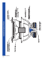
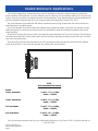
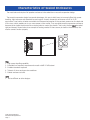
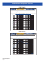
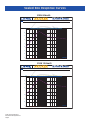
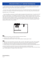
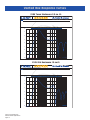
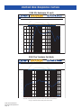
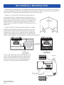
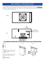
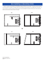
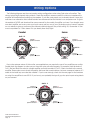
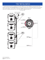
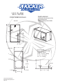
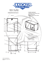
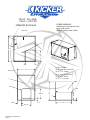
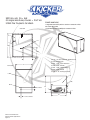
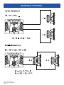
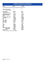
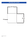
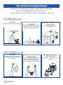
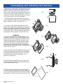
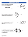
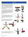
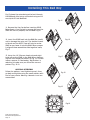
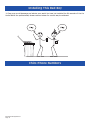
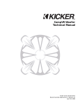
SOLOX Technical Manual Kicker SoloX Subwoofer Recommended Applications / Version 1.1 January 14, 2002 Features y Mica Filled Polypropylene with a Titanium Deposit Impregnated Cone An Ultra High Performance look that makes the SoloX truly a statement piece. Look at it this way, we needed a high tech look to the SOLOX because the first thing you notice about speakers are their cones! y Advanced Cone Technology The outer edge of the cone has been rolled to increase cone rigidity to decrease cone flex under high excursion. The cone gives you deeper and stronger bass at higher listening levels with less distortion due to less tendency to flex. Because, when a woofer cone flexes, there is a loss of output. This loss of output translates into less bass. y Massive Surround Radius High SPL=VMAX=Cone area + Xmax + surround radius. What does this mean? According to Dr. Koneairea, the Vmax of the driver takes into account the cone area as well as the Xmax of the driver. To increase the Xmax - the distance the cone can move in one direction - the surround must be large enough to handle the demands. Taking this into consideration, the new SOLOX surround has been designed to handle the massive power needed for high SPL. y SPAIR (Simple Pull Apart Insertable Replacement) (Patent Pending) Because this woofer assembly weighs over 100lbs. (or 45.36 kGs. to you across the pond!) we developed a removable soft parts assembly to ease the installation and removal of the speaker. Makes repairs ...a snap! y SLAM (SPAIR Lockdown Attachment Mechanism) The aluminum frame attached to the SPAIR properly secures the removable speaker assembly (SPAIR) to the BAM (Basket And Motor assembly). With the excursion capabilities of this woofer it is very important that there is a tight seal against the BAM to allow the speaker to perform properly. y SPLAT (Speaker Precise Location Alignment Tool) Locates and anchors the BAM to the baffle of your enclosure. A picture frame like structure that must be used to insure a solid mount. It is inserted into the enclosure prior to the BAM being installed. Once the BAM is in place the SPLAT is located on the baffle around the rear of the speaker. The supplied mounting hardware should be inserted to make sure the SPLAT stays put. Once all 4 screws are sufficiently tightened, the BAM will be secure. y ARCTIC Cap (Aluminum Rapid Cooling Thermal Induction Centering Cap) Mounted on top of the extended pole--piece it is responsible for insuring the voice coil on the SPAIR is properly centered when inserted into the BAM, adds more mass for increased thermal transfer from the voice coil to the pole piece and channels air into the “X” Vent for increased cooling. y S4 Quad Spider Array One spider cannot handle the demands alone. Our engineers had to design a quad spider array that would keep up with the demand of the enormous motor structure. 4 Poly nomex spiders make up the array to properly center the voice coil under high excursion. y Triple Stack Custom Tooled Magnets With excursion capabilities of this monster speaker a single magnet structure just would not do. We figured it worked for Wendy’s, why not us? Triple stack is the only way to satisfy even the largest appetite for sound and with a BAM this big, a single just wouldn’t fill the appetite of the SOLOX. y Stitched Surround A signature of KICKER woofers has always been the stitched surround. It prevents the surround from separating from the cone at high excursions. When the woofer is moving back and forth it puts a lot of strain on the adhesive that is holding the surround to the cone and often causes the two to separate. Stitching the surround to the cone eliminates this from happening. If stitching were inexpensive, everybody would do it! Kicker SoloX Subwoofers Recommended Applications Page 2 Features cont. ) Kicker was one of the first companies to switch to the Inverted Structural y ISD (Inverted Structural Dome Dome. We have designed a cone with a groove for the ISD to lock into, further adding strength to structure. When a cone reaches it’s peak it wants to buckle because it’s momentum keeps it moving out. The ISD provides structural support for the cone to resist buckling. NOTE: When the cone buckles, the output of the woofer decreases. Therefore, the ISD is not just a cosmetic thing, it is an integral part of the woofer to maintain it’s maximum performance. While everyone has outies we decided innies work better! y Dual Ultra-Length High-Temp 3.5” Voice Coils For high excursion, increased power handling and flexible wiring options. With the increased circumference of the coil we needed to increase the size of our pole-piece. Our engineers locked themselves in a room and got out their slide rules and calipers to come up with the proper size pole needed for such an enormous motor structure. OK, so they just flipped a coin! y Strain Relief Boots for Tinsel Lead Wires Large heavy gauge tinsel lead wire with strain relief boots. Because the cone moves in and out with such force our engineers came up with strain relief boots for the lead wires. This reinforces the lead wire so it will not break under stress. y B3-Link 3-Way Connection System which allows you to use 1. Binding post 2. Terminal Block 3. Barrier strip for connecting the speaker wires. y Uniplate V.2 with Vented Hyper-Extended Pole (Patent Pending) 1. Utilizes “X” Vent technology to insure proper heat dissipation. Slits were cut into the pole piece. The slits increase the surface area of the pole as well as channel the air down the pole keeping it cooler. 2. Provides enhanced heat transfer for cool operation and maximum power handling. The heat is transferred from the pole piece to the back plate, effectively acting like a radiator in an engine. This lowers the operating temperature of the voice coil. Note:The increase in temperature increases the impedance of the speaker. This results in lower output and is referred to as Power Compression. 3. Reduces non-linear magnetic fields around the voice coil gap for superior cone motion control. The extended pole assures the voice coil is always in the magnetic field when moving peak to peak. When the speaker reaches it’s Xmax, the voice coil is still in the gap between the pole piece and magnet structure due to its extended pole-piece. 4. Releases pressure under ISD for freer cone motion and enhanced low frequency response. Air trapped under the ISD is forced out though the pole-piece to allow the cone to move freely. Heat and pressure build up under the ISD and need to be released to allow the speaker to function properly. Kicker SoloX Subwoofers Recommended Applications Page 3 SoloX Cutaway View Kicker SoloX Subwoofers Recommended Applications Page 4 Break-In Procedure Thank you for your support of Kicker products, and especially our SOLOX square subwoofer. The SOLOX is truly a unique product in the world of subwoofers. Our technical and R&D staffs have designed some extreme enclosures beyond the small sealed boxes KICKER woofers are famous for. They have truly outdone themselves with the SOLOX. In this paper we will explore some applications for the SOLOX complete with box drawings and cut sheets plus some important information regarding the break-in period for this ground-breaking speaker. Important Break-In Information Due to the complex nature of the SOLOXs they require a little extra time to break-in. Especially in sealed enclosures, break-in is a must in order for woofers to produce optimum low bass response. Due to the high performance suspension system incorporated in the SOLOX it is very stiff “out of the box”. Approximately two weeks of daily playing will allow the suspension to break-in and reach its optimum equilibrium. The “broken-in“ sub will exhibit stronger bass performance, smoother response, and greater low bass extension. For those of you with more sophisticated audio equipment, the SOLOX can be broken-in on the test bench overnight with the following procedure. SOLOX Freeair Break-in Procedure 1. Connect the speaker to a power amp with a minimum of 100 watts. The speaker should not be mounted in any enclosure - just freeair. Please make sure it will not walk off the bench while it is playing! 2. Connect an audio generator to the input of the power amp, and adjust the generator to approximately 25Hz. 3. Now adjust the gain on the amplifier and generator so that the cone is moving to Xmax. This can be determined visually by looking at the “blur depth” of the logo on the ISD. A close approximation will do. On the S18X this will be about 1-1/2”. NOTE: Keep in mind that as the speaker is used under normal conditions the break-in will continue, so if you don’t have time for the complete break-in period the speaker will still break-in itself under normal usage. Kicker SoloX Subwoofers Recommended Applications Page 5 Sealed Enclosure Applications The SOLOX is designed for Vented enclosure/ High SPL applications and that is where maximum output and power handling will be achieved. If you are willing to give up maximum SPL and power handling for more low bass output, then you can utilize our sealed enclosure recommendations.These sealed enclosure recommendations will give the smoothest response with the most energy at really low frequencies, around 20 to 30 Hz. The recommended Tuner sealed box will deliver massive amounts of high impact bass and can be driven with punishing levels of amplifier power. One of the benefits of the SoloX series high performance suspension system is that they can operate in larger sealed enclosures for ultra low bass performance (SUV applications) while still maintaining excellent control and power handling. SOLOX series woofers also perform well in any sealed enclosure between the Tuner and SUV sizes. These systems will exhibit some benefits of both (high impact and low extension) generally sounding more like the box to which they are most closely sized. These enclosure volume recommendations are for the airspace inside the enclosure and include the displacement of the woofer. Do not make the airspace any greater than recommended. S18X Recommended Enclosures Model Tuner minimum: 3 cu.ft., F3= 31.6Hz, Pmax= 6000W Tuner maximum: 6 cu.ft., F3= 26.5Hz, Pmax= 3500W SUV minimum: 9 cu.ft., F3= 24.8Hz, Pmax= 3000W SUV maximum: 12 cu.ft., F3= 23.8Hz, Pmax= 2500W For more enclosure choices check out our website www.kicker.com or call Jerimy “WB” in Technical Services at 1-405-624-8583. Kicker SoloX Subwoofers Recommended Applications Page 6 Characteristics of Sealed Enclosures The most basic and simple of all speaker enclosures is the sealed box or acoustic suspension design. The acoustic suspension design has several advantages; it is easy to build, easy to tune and offers high power handling, tight response and extended low end output. Acoustic suspension enclosures roll off at 12 dB per/octave. Cone motion is better controlled at all frequencies because of the constant pressure on the back side of the cone, which enables you to run more power to the woofer. They are called acoustic suspension enclosures because the air inside the box acts like a viscous brake to control the woofer. That is why the box must be sealed tight and braced. Shown below is an example of bracing needed. If there are any air leaks in the enclosure, the woofer cannot function properly. Pros 1 - High power handling capability 2 - Extended low frequency response and smooth rolloff (12 dB/octave). 3 - Excellent transient response. 4 - Tolerant of minor enclosure size variations. 5 - Easiest enclosure to build. Cons 1 - Not as efficient as other designs. Kicker SoloX Subwoofers Recommended Applications Page 7 Sealed Box Response Curves S18X 3.0cu.ft. C SOLOX S18 Sealed Tuner Minimum Response Curve 90 dB Graph 1 > Acoustic On Axis Response: SPL, Phase 85 80 75 70 65 60 55 C 50 10 Frequency 50 100 Hz 500 1K S18X 6.0cu.ft. C SOLOX S18 Sealed Tuner Maximum Response Curve 90 dB Graph 1 > Acoustic On Axis Response: SPL, Phase 85 80 75 70 65 60 55 C 50 Kicker SoloX Subwoofers Recommended Applications Page 8 10 Frequency 50 100 Hz 500 1K Sealed Box Response Curves S18X 9.0cu.ft. C SOLOX S18 Sealed SUV Minimum Curve 90 dB Graph 1 > Acoustic On Axis Response: SPL, Phase 85 80 75 70 65 60 55 C 50 10 Frequency 50 100 Hz 500 1K S18X 12.0cu.ft. C SOLOX S18 Sealed SUV Maximum Curve 90 dB Graph 1 > Acoustic On Axis Response: SPL, Phase 85 80 75 70 65 60 55 C 50 Kicker SoloX Subwoofers Recommended Applications Page 9 10 Frequency 50 100 Hz 500 1K Ported/Vented Enclosure Applications Ported SOLOXs incorporate massive slot loaded ports with ultra low air velocity for ground pounding street bass that will make your hair stand on end (if you have any left)! These are the enclosures of choice for outrageous street bass and high performance SPL contests. The following chart shows three recommended ported enclosures for each Solo-Baric driver. Tuner has increased bass efficiency over a sealed enclosure, yet can still fit in tighter applications. It is the smallest design that will work well for each woofer. Although it is the smallest ported enclosure the output from 30 to 80 HZ will be considerably higher than that of a sealed box. The two other ported designs have proportionately more output in this region. SUV is a medium sized enclosure that will kick out bass that can be heard for blocks away. And it does go LOW! SPL is a high efficiency enclosure that delivers the output necessary to put up the big numbers. If space is not at a premium and you want to get the most from your SOLOX, try one of these designs. You won’t be disappointed. You may want to take a look at The Truckers Car Wash Enclosure if you got the room for it! Note: You must add the port volume to the volume of the box! See the cut sheets. Recommended Ported Enclosure – High Efficiency – Model S18X Tuner 5 cu.ft. Port: 60sq.in. x 14.5” Fb= 35Hz, Pmax= 5000W (with 25hZ subsonic filter) SUV 10 cu.ft. Port: 150 sq.in. x 21” Fb= 35Hz, Pmax=4500W (with 25hZ subsonic filter) SPL 10 cu.ft. Port: 300sq.in. x 9” Fb= 56Hz, Pmax= 10000 (Above tuning freq. only) * See below! *This enclosure is intended for SPL ONLY! It is designed to be used with test tones above 56Hz! Playing music with frequencies below 56Hz will result in very, very bad things happening!! In other words, THIS IS AN SPL ENCLOSURE ONLY! NOTE: The use of a subsonic filter is necessary to insure the life of the woofer in a ported enclosure. Kicker SoloX Subwoofers Recommended Applications Page 10 Characteristics of Vented Enclosures A vented enclosure is not much more complex than a sealed box. It consists, basically, of a box with a hole in it. However, despite its simple design, vented boxes are considerably harder to get good performance from than sealed boxes - although many times the extra effort can be worth it. The vent in the enclosure interacts with the volume of air in the cabinet and the driver to help increase output and reduce cone excursion at and around the tuning frequency. In fact, at box tuning, almost all the bass is produced by the vent - NOT the woofer. The trick in building a vented box is to get the right size enclosure and the right size vent. You can’t be to far off on either of these factors or your speaker’s performance will suffer. In particular, using a too-small box or a toohigh vent tuning frequency can eliminate bass instead of increasing it. Porting a sealed box that is too small usually does nothing to improve frequency response. The vents placement within the enclosure is also important. You must leave at least the equivalent of the vents diameter between the vent and any inside wall. For example, you would not place a vent with a 3” diameter within 3” of any wall. The same is true for clearance between the vent opening and the bottom of the enclosure. Pros 1 - Reduced cone excursion and reduced distortion around vent tuning. 2 - Increased output capabilities around vent tuning. 3 - Vented boxes give you that extra “Bump” that is preferred in certain types of music. Cons 1 - Total loss of cone control below vent tuning, which can result in high distortion and driver mechanical failure. 2 - Midrange sound coming from inside the box through the vent can produce unpleasant sound coloration. 3 - Vented enclosures are more sensitive to changes such as temperature, humidity and driver fatigue. 4 - Enclosure design is more complex and the enclosure itself must be more solidly constructed because internal pressure at frequencies around vent tuning can be nearly twice as high as a sealed enclosure. 5 - Vented enclosures usually don’t sound as fast as sealed boxes because the resonant effects of the vent tuning which is always slightly out of phase with the driver’s output. Kicker SoloX Subwoofers Recommended Applications Page 11 Vented Box Response Curves S18X Tuner Enclosure 5.0 cu. ft. C SOLOX S18 Ported Tuner Response Curve 95 dB Graph 1 > Acoustic On Axis Response: SPL, Phase 90 85 80 75 70 65 60 C 55 10 Frequency 50 100 Hz 500 1K S18X SUV Enclosure 10 cu.ft. C SOLOX S18 Sealed SUV Response Curve 95 dB Graph 1 > Acoustic On Axis Response: SPL, Phase 90 85 80 75 70 65 60 C 55 Kicker SoloX Subwoofers Recommended Applications Page 12 10 Frequency 50 100 Hz 500 1K Vented Box Response Curves S18X SPL Enclosure 10 cu.ft. C SOLOX S18 Sealed SPL Response Curve 90 dB Graph 1 > Acoustic On Axis Response: SPL, Phase 85 80 75 70 65 60 55 C 50 10 Frequency 50 100 Hz 500 1K S18X The Truckers Car Wash KDL SOLOX S18 The Trucker's Car Wash 80 dB Graph 1 > Acoustic On Axis Response: SPL, Phase 75 70 65 60 55 50 45 C 40 20 Frequency 100 500 1K Hz 5K 10K We know what you’re thinking...why The Trucker’s Car Wash? It’s simple Beavis... It’s Big, it’s Bad and it doesn’t take $&@* off of no one! Kicker SoloX Subwoofers Recommended Applications Page 13 20K Box Building & Mounting Hints All the cubic feet numbers given in the supplied charts include the displacement of the woofer. For the ported boxes the displacement of the port must be added to the final design. It will be impractical to use round ports for these designs. The rectangular port information given will yield the best results. Always use 1” or thicker MDF and make sure all the joints are secure and well sealed. The peak pressure in a ported box can exceed that of a sealed enclosure. All of these designs need some internal bracing. Be sure to add a minimum 4”x 4” triangle braces between each of the larger unsupported panels. Kicker recommends using a good grade of wood glue and silicone sealer for an airtight box. X Note:If you prefer an ultra-smooth bass response, you should loosely fill your ported SOLOX Enclosure with polyfil. If you do so, the entrance to the port (inside the box) must be covered with hardware cloth, chicken wire, or expanded metal to prevent the polyfil from being blown out through the port. Use of polyfil will slightly decrease efficiency, but will deepen and extend low bass response. X X 50 % filled with Polyfil Chicken Wire or Expanded Metal Chicken Wire or Expanded Metal Do not install a ported box with the port against a solid surface. The port opening must remain unobstructed. Use the smallest dimension of the rectangular port as the minimum amount of space required between the port and any surface to insure unrestricted airflow. At Least 4 " Hatchback OR Trunk Kicker SoloX Subwoofers Recommended Applications Page 14 Box Building & Mounting Hints If you would like to use a vented enclosure, but the box designs we provide you with (in this manual) do not fit because of width or depth, the designs can be modified. The shape of the enclosure is not vital, but The Volume Is. The volume, of the design you choose, must stay the same. The following diagrams provide you with some help to insure your enclosure is built correctly. Front 45° Wedge Round Over Inner Corner Top Remember: If you are going to bend the port at 90°° you will need to add 1/2 of the ports height to the length! See Below. Example: (Fig. 1) Hport = 3” Wport = 10” Lport = 20” Fig. 1 Fig. 2 3" 3" 10" 10" (Fig. 2) Since Hport is 3” you need to add 1.5”( 1/2 of Hport) to Lport. This means that L1 + L2 = 21.5” Always measure L1 and L2 down the center to get an accurate measurement! Kicker SoloX Subwoofers Recommended Applications Page 15 L2 20" 3" L1 Box Building & Mounting Hints Here are a couple more examples of the different shape enclosures you can build. The woofer can be mounted on the same side as the port or the back side of the enclosure can be slanted to fit up against your back seat.. On the cut sheets we provide, change the dimensions to accommodate the woofer and the vent on the same side. Make sure the internal volume does not change! Top Side OR Top Kicker SoloX Subwoofers Recommended Applications Page 16 Side Wiring Options The following diagrams are the most popular wiring configurations when using Dual voice coil woofers. They show a typical single channel wiring scheme. Check the amplifier’s owners manual for minimum impedance the amplifier will handle before hooking up the speakers. If your like most people, you’ve already thrown it away, but wait there is an alternative. Most manufacturers have discovered that the internet is on computers now. So go to the website of KICKER and download the owners manual for the model of amplifier you have. If you bought someone else’s amplifier, we’re sorry, save your lunch money and buy one of ours. We always post our owner’s manuals on our website to give our consumers the ultimate technical support! Okay a little wiring 101, Remember: 4 Ohm mono is equivalent to 2 Ohm stereo. But you already knew that, Right! Series Parallel + Amplifer + Speaker Connection Amplifer + Speaker Connection COIL 1 #Ω COIL 2 #Ω COIL 2 #Ω - Coil 1 - Coil 2 - Coil 1 Coil 2 Amplifer Speaker Connection Amplifer Speaker Connection COIL 2 #Ω - COIL 1 #Ω COIL 1 #Ω Coil 2 + Coil 1 COIL 1 #Ω Coil 1 COIL 2 #Ω + Coil 2 + Due to the extreme nature of this woofer, some applications may require the use of two amplifiers per woofer. Double check the diagram to make sure you have the voice coils wired properly. For example, both terminals of Coil 1 (Red and Black) are wired to a single amplifier and both terminals of Coil 2 ( Silver) are wired to the second amplifier. Please make sure to check the polarity. We know that sounds obvious, but even a seasoned veteran of 2 weeks in the install bay can make that mistake! ! If you’re man enough, check out the next page for the lowdown on using four amplifiers to one SOLOX. If you’re not, your probably the type of guy who puts import racing decals on your camaro! + Coil 1 COIL 1 #Ω Amplifer 2 Speaker Connection Amplifer 1 + Speaker Connection COIL 2 #Ω - Coil 1 - COIL 1 #Ω Coil 2 Amplifer 2 + Speaker Connection Coil 2 Kicker SoloX Subwoofers Recommended Applications Page 17 Amplifer 1 Speaker Connection COIL 2 #Ω + “The” Wiring Option If you are using our KX1200.1 amplifiers, you have the ability to run Four amplifiers to one mammoth SOLOX woofer! For those of you who payed attention in math, one less than five, one more than three, or two more than two! In other words a TON OF POWER! Check out the diagram below for the lowdown. If you still have questions check out our website www.kicker.com or call Jerimy “WB” in Technical Services at 1-405-624-8583. 3.5mm/ 1/8" Tip Sleeve Mono 2 conductor Primary AMP SIGNAL IN AMP STRAPPING OUT Out In IN Coil 1 + COIL 1 #Ω Amplifer 1 Speaker Connection COIL 1 #Ω Secondary AMP - + Coil 2 COIL 2 #Ω Coil 1 Amplifer 1 + Speaker Connection - COIL 2 #Ω + Coil 2 Primary AMP - AMP STRAPPING SIGNAL IN OUT Out In IN Amplifer 2 Speaker Connection + Secondary AMP + Kicker SoloX Subwoofers Recommended Applications Page 18 Amplifer 2 + Speaker Connection + 5.0 cf, Fb=35Hz .50 cf = Port Vol. POWER HANDLING: S18X2-TUNER Enclosure 5000W with 25Hz Subsonic Filter set at 24dB/Octave Without subsonic filter 2500W Side View B D E 27 14-1/2 3 22 Front View Cut List: 3/4" MDF (2) 25" x 19" Top & Bottom(A) (2) 22" x 19" Sides(B) (2) 20" x 25" Front & Back(C) C (1) 14.5" x 20" Port(D) (6) 4" x 4" Gusset(E) A R2-7/8 R3/8 16-11/16 19 3 1 1 2-21/32 2-21/32 16-11/16 Kicker SoloX Subwoofers Recommended Applications Page 19 20 10.0 cf, Fb=35Hz 1.82 cf = Port Vol. POWER HANDLING: S18X2-SUV Enclosure 4500W with 25Hz Subsonic Filter set at 24dB/Octave Without subsonic filter 2250W Side View B D E 37 21 6 Cut List: 3/4" MDF 27 (2) 25" x 35" Top & Bottom(A) Front View (2) 27" x 25" Sides(B) (2) 25" x 35" Front & Back(C) (1) 21" x 25" Port(D) (6) C 4" x 4" Gusset(E) A R2-7/8 R3/8 16-11/16 25 1 6 2 5-5/32 16-11/16 Kicker SoloX Subwoofers Recommended Applications Page 20 25 1 10.0 cf, Fb=35Hz 1.56 cf = Port Vol. POWER HANDLING: S18X2-SPL Enclosure 10000W with 56Hz Subsonic Filter set at 24dB/Octave Without subsonic filter 5000W Side View B D E 37 9 12 Cut List: 3/4" MDF 27 (2) 25" x 35" Top & Bottom(A) Front View (2) 27" x 25" Sides(B) (2) 25" x 35" Front & Back(C) C (1) 9" x 25" Port(D) (6) 4" x 4" Gusset(E) A R2-7/8 R3/8 16-11/16 25 1 12 1 2 5-5/32 16-11/16 Kicker SoloX Subwoofers Recommended Applications Page 21 25 2001.8cu.yds, Fb= 6Hz (2) single axle Dump trucks = Port Vol. POWER HANDLING: S18X2-The Trucker's Car Wash 1 Large Nuclear Facility with a Uranium Transsonic Filter set at 384 dB/Octave Side View 1 Small Nuclear Facility without Transsonic filter B D E 96ft 23ft 8ft Cut List: 1 ft. thick Californian Redwood trees 96 years old preferred (2) 25ft. x 94ft. Top & Bottom(A) 27 (2) 27ft. x 25ft. Sides(B) Front View (2) 25ft. x 94ft. Front & Back(C) (1) 25ft. x 23ft. Port(D) (6) 6ft. x 6ft. Roofing trusses(E) C A R 3ft. R2-7/8 25 16-11/16 inches 1 8 1 25 16-11/16 inches Kicker SoloX Subwoofers Recommended Applications Page 22 Resistance Formulas R BASS BOOST (dB) 9 6 12 3 15 0 18 GAIN 0 11 X-OVER FREQ. (Hz) 50 200 R BASS BOOST (dB) 9 6 12 3 15 0 18 GAIN 0 11 X-OVER FREQ. (Hz) 50 Kicker SoloX Subwoofers Recommended Applications Page 23 200 Thiele/Small Parameters Model S18X1 Nominal Impedance 1 (Coil impedance) SPL 1W/1M 90.27 Displacement, cc 3930 Displacement, CuIn 239.8 Mounting Depth 11-3/8 Revc 2.05 VC Inductance, mH 3.247 Sd, SqM 0.1426 BL 31.45 Vas, Liters 185.64 Vas, CuFt 6.55 Mms, gms 859.8 Fs 21.4 Qms 8.838 Qes 0.240 Qts 0.233 Pmax, Peak watts 10000 RMS watts 5000 EXmax, mm 24.48 ( Excursion maximum, see next page.) Kicker SoloX Subwoofers Recommended Applications Page 24 S18X2 2 89.7 3930 239.8 11-3/8 4.07 4.289 0.1426 40.36 177.61 6.27 836.5 22.18 7.83 0.291 0.281 10000 5000 24.48 Excursion Maximum 101 As you read the specifications for your SoloX you may notice a new parameter called EXmax. EXmax stands for Excursion Maximum and expresses the maximum one-way linear excursion capability of the driver based on: 1. Linearity (how much distortion the speaker system exhibits) 2. Excursion limits of the moving parts (how far it can move before it breaks) 3. BL (the strength of the motor assembly) In other words, EXmax tells you just how far the woofer is capable of moving before reaching the physical limits of the moving parts, diminishing motor strength and NOT taking into consideration how much distortion is created. Strange statement huh?! Let’s break it down. When a woofer is used for EXTREME SPL (notice that...EXTREME SPL) applications, it is driven well out of the linear range that would be used if sound quality (low distortion/high linearity) were your goals. Any woofer can be driven to the point where it starts exhibiting non-linear response. At this point the distortion of the system starts to rise and BL starts to fall off. There may be more linear excursion available but your ears tell you it is starting to sound bad, un-natural, so you stop turning up the volume as you have reached the limits of that system for a linear response (low distortion). But what if low distortion was not a measuring criteria? What then? This is where EXmax comes into play. SPL is all about compressing air, and besides, who cares if it is 40% distortion, Mr. SPL Microphone sure doesn’t! Your not listening to it for pleasure, only trying to compress the air inside a vehicle to impress a microphone. We personally would never want to listen to a system at 40% distortion for more than about .05 seconds...tops.(most people under the age of say...umm...80 would agree) But if you are standing outside a vehicle sealed up tighter than a frog’s bum burping test tones to get a really big number on a meter, subwoofer linearity (distortion) is not a factor. Compressing the air is your goal in this scenario, not necessarily linearity. This does not mean a high SPL sub is designed to be non-linear or exhibit high distortion, it just means ANY sub driven into non-linearity will exhibit high distortion. But if the sub can continue to compress air even though it is operating at a high distortion level you will get more SPL. Make sense? Great! The SoloX was designed to excel in vented enclosures and achieve extreme SPL numbers when asked to do so. That is why the EXmax specification is shown, to let you know just how far this baby can go when asked to bring the house down! The EXmax figure is derived from driving the SoloX until 55% linearity is achieved and measuring the EXmax at that point. The SoloX has a TREMENDOUS amount of motor strength and an over-built cone/suspension system which allows it to drive well into the non-linear operating range and still compress air to make SPL. So what you are saying is that the SoloX is a high distortion/high SPL subwoofer? No! No! No! We are saying the SoloX is capable of EXTREME SPL output and at those levels you will have high distortion. (ALL subs have high distortion when played into a very non-linear range) If the SoloX is played under NORMAL (in other words... NOT EXTREME SPL) conditions it can play very loud and very low with very high linearity/low distortion, just like you would expect from a KICKER subwoofer. Now that you know what EXmax is and what it means, hit the wood shop, eat some dust and get your enclosure built. Your SoloX wants to go outside and play! Kicker SoloX Subwoofers Recommended Applications Page 25 Mounting Hole Cutouts Kicker SoloX Subwoofers Recommended Applications Page 26 “The Adventures Of Sam Stikman” If you did not take the time to check out Sam before, Please take a minute to read about SAM. It will save you a trip to the Hospital, or worse, a broken woofer, an empty wallet, & NO chics! The WRONG way! SEE SAM! (SAM failed to read the Instructions!) SEE SAM FLAT ON HIS BACK IN AGONY! (If SAM had read the Instructions he would have known this speaker weighs more than a Mini Cooper!) SEE SAM HAULED OFF IN AN AMBULANCE! (Don’t be a SAM ...Read the Instructions!) AMBULANCE RTFM The CORRECT way! SEE SAM! (See SAM read the Instructions!) (He now knows it weighs more than a Mini Cooper!) m it a nd g r or ya ym si trf gigbshe ue i lr pk m Kicker SoloX Subwoofers Recommended Applications Page 27 SEE SAM & SID FOLLOW THE INSTRUCTIONS! (Sam knew the speaker weighed more than a Mini Cooper, so he asked his friend Sid for help. In return Sid gets to cruise with Sam.) SEE SAM & SID CRUISIN’ WITH THE CHICS! (Be a SAM ... Chics dig guys who can read!) Unwrapping and Installing This Bad Boy Now that you have read “The Adventures of Sam Stikman” again and decided on which enclosure design to use, you may now remove the SoloX from it’s box. Please follow the instructions lined out here to insure proper installation. Have you found the “Optional” DVD yet? We haven’t either! Huh, must be part of the STXL package! Fig.1 1. With assistance from a friend (or an engine hoist) remove the SoloX from the cardboard facilitation chamber or “box” if you will. Fig. 1 2. Once out of the carton remove the (4) four acorn head nuts and (8) eight bolts securing the SPAIR to the BAM and wood baffle assembly. Place SPAIR in safe clean location! This does not mean on the floor next to the car where it gets kicked and tripped over everytime you walk by. Fig.2 ATTENTION! 3. Install the Gap Cap into the BAM around the pole-piece to protect the motor assembly from debris while you are installing the woofer. If any metal shavings were to fall into the gap, they would be impossible to remove! Please use the Gap Cap! If this were not important we would have taken the money we spent to design and produce them and bought a spa for the tech bay! So use the cap ! Fig.3 Fig.2 Fig.3 Fig.4 4. With the Gap Cap now installed remove the (4) double end threaded studs that lock the BAM to the wood baffle assembly. Be careful not to let the SPLAT fall on you foot otherwise... you guessed it, splat! Fig.4 The SPLAT and wood baffle will now come free from the BAM. The baffle will now become your mounting template. Fig.5 5. Place the wood template on your enclosure baffle to mark the holes for mounting. Make sure it is in the correct spot before you start cutting. Remember, “Cut twice, but only mark once!” Fig.6 Kicker SoloX Subwoofers Recommended Applications Page 28 Fig.5 Fig.6 Installing This Bad Boy 6. Once the holes are marked remove template. Using a jigsaw cutout the woofer hole and use a 3/8” drill bit for the mounting holes. Fig.7 Fig.7 ACHTUNG! ATTENTION! You will need assistance for the following steps! Baffle 7. Insert the SPLAT into the cutout and move into position. We know what your thinking ...How can this fit in through the hole. Relax tried it once and it worked, so we put it into production! Fig.8 8.Use masking tape to temporarily hold the SPLAT in place while securing the BAM. This tape can be removed after the corner hardware has been started. Fig.9 9. With your assistant, insert the BAM and start the corner hardware. Now is the time you remove the unidirectional bonding strip! (Tape) Tighten the double threaded studs to secure the BAM to the baffle. Now take inventory to make sure nothing dropped on the floor while wrestling the big unit into position. Fig.10 Kicker SoloX Subwoofers Recommended Applications Page 29 Fig.8 Fig.9 Fig.10 B3 Link 10. Before you pull the wires through the BAM, you must decide which of the three metods you will use. The parts needed for this step are shown in Fig. 11. In addition to the included parts you will need a brain larger than a pea. If you are not sure about the size of a pea, our graphic artist has provided one here for your use. Keep in mind, the pea is for measurement purposes only and has no real purpose in the final installation. The Binding posts must be removed when using the other methods of connecting the speaker wire. When connecting the wire make sure you are using proper polarity, otherwise the POLARITY POPO will be after you! If you reverse the polarity you’ll know it, that 18 inch woofer will slam like a solid 8 incher! Fig.12-15 Fig.11 PEA Hooker Audio 8 ga Speaker Wire Gary Biggs Approved Fig.12 Fig. 12 shows the Binding Post method of connecting the speaker wires. Make sure the binding post is tight so the wires will not come out. This is the B3 Link option as shipped from factory. Fig. 13 shows the Barrier strip method of connecting the speaker wires. Make sure the screw is tight so the wires will not come off. Hooker Audio 8 ga Speaker Wire Hooker Audio 8 ga Speaker Wire Gary Biggs Approved Gary Biggs Approved Hooker Audio 8 ga Speaker Wire o e di ir Au W d r er ove ke ak ppr o e A s o H Sp Bigg ga ry 8 Ga Kicker SoloX Subwoofers Recommended Applications Page 30 Hooker Audio 8 ga Speaker Wire Gary Biggs Approved Gary Biggs Approved Fig. 14 shows the Terminal Block method of connecting the speaker wires. Make sure the screw Fig.14 is tight so the wires will not come out. Hooker Audio 8 ga Speaker Wire 8 Fig.13 G ar H ga oo S ke y pe r A Big a gs ke ud Ap r io W pr ov ed ire Gary Biggs Approved Installing This Bad Boy Fig.15 shows the wires being pulled out through the BAM and after being connected using one of our stylish B3 Link Methods! Fig.15 11. Remove the Gap Cap before inserting SPAIR. Relax Beavis, if you forget to remove the cap, the SPAIR will not fit properly into the BAM. Fig.16 Fig.16 12. Insert the SPAIR back into the BAM. Be careful not to damage the voice coil. The double threaded studs and the ARCTIC Cap will help to center SPAIR as you lower it into the BAM. When properly aligned these assemblies slide together easily. Fig.17 13. Using the 1/4”-20 acorn head nuts and eight bolts secure the SPAIR to the BAM. When tightening the nuts follow the pattern in Fig. 19. This will insure a proper fit. Remember, “Big Brother” is watching to make sure you follow the correct pattern! Fig. 18-19 ACHTUNG! ATTENTION! Follow the pattern, hand tightening each, then go back and tighten using the same pattern with tool of your choice. Warning: Hammer is not recommended! Fig.17 Fig.18 Fig.18 Fig.19 Kicker SoloX Subwoofers Recommended Applications Page 31 Installing This Bad Boy 14. Pop open a cold beverage and admire your work! You have just installed the 8th wonder of the Car Audio World! See professionally drawn cartoon below for correct way to celebrate! Chics Phone Numbers Kicker SoloX Subwoofers Recommended Applications Page 32 Hookups for Freebies Who Owes Me Cash Kicker SoloX Subwoofers Recommended Applications Page 33 SPEAKER SYSTEMS LIMITED WARRANTY Stillwater Designs warrants this product to be free from defects in material and workmanship under normal use for a period of one (1) year from date of original purchase from an Authorized Kicker Dealer, unless this product is labeled “B Stock”, in which case it is warranted for ninety (90) days from date of purchase. Should service be necessary under this warranty for any reason due to manufacturing defect or malfunction during the warranty period, Stillwater Designs will replace or repair (at its discretion) the defective merchandise with equivalent merchandise at no charge. Warranty replacements on “BStock” may have cosmetic scratches and blemishes. Discontinued products may be replaced with equivalent products. This warranty is valid only for the original purchaser and is not extended to owners of the product subsequent to the original purchaser. Any applicable implied warranties are limited in duration to a period of the express warranty as provided herein beginning with the date of the original purchase at retail, and no warranties, whether express or implied, shall apply to this product thereafter. Some states do not allow limitations on implied warranties, therefore these exclusions may not apply to you. This warranty gives you specific legal rights; however you may have other rights that vary from state to state. WHAT TO DO IF YOU NEED WARRANTY OR SERVICE Defective merchandise must be returned to your local Authorized Stillwater Designs (Kicker) Dealer for warranty. Assistance in locating an Authorized Dealer can be obtained by writing or calling Stillwater Designs direct. You can confirm that a dealer is authorized by asking to see a current authorized dealer window decal. If it becomes necessary for you to return defective merchandise, call the Kicker Customer Service Department at (405)6248510 for a Return Authorization (RA) number. Package all defective items in the original container or in a package that will prevent shipping damage, and return to Stillwater Designs, 5021 North Perkins Road, Stillwater, OK 74075 The RA number must be clearly marked on the outside of the package. Return only defective components. Return of entire cabinets, system packs, pairs, etc. increases your return freight charges. Non-defective items received will be returned freight collect. Include a dated proof-of-purchase from an Authorized Dealer. Warranty expiration on items returned without proof-ofpurchase will be determined from the manufacturing date code. Coverage may be invalidated if this date is greater than 18 months previous to the date item is sent in. Freight must be prepaid; items received freight collect will be refused. Failure to follow these steps may void your warranty. Any questions can be directed to the Kicker Customer Service Department at (405)624-8510. WHAT IS NOT COVERED? This warranty is valid only if the product is used for the purpose for which it was designed. It does not cover: • Install slips (screwdriver holes) • Items previously repaired by any • Damage caused by exposure to water unauthorized repair facility. and/or excessive heat. • Items returned from unauthorized • Damage through negligence, misuse, or individuals or dealers. accident. • Return shipping on non-defective items. • Items physically damaged due to abuse. • Speakers damaged due to amplifier • Freight damage. clipping or distortion. • The cost of shipping product to Stillwater • Speakers with silicon caulk used for gasket Designs Service. material. HOW LONG WILL IT TAKE? Stillwater Designs maintains a goal of 24-hour service for all returns. Delays may be incurred if lack of replacement inventory or parts is encountered. INTERNATIONAL WARRANTY Contact your International Stillwater Designs dealer or distributor concerning specific procedures for your country’s warranty policies. P.O. Box 459 • Stillwater, Oklahoma 74076 • U.S.A. • 405 624-8510 WARNING: KICKER drivers are capable of producing sound levels that can permanently damage your hearing! Turning up a system to a level that has audible distortion is more damaging to your ears than listening to an undistorted system at the same volume level. The threshold of pain is always an indicator that the sound level is too loud and may permanently damage your hearing. Please use common sense when controlling volume! February 2003 SOLOX Limited Warranty Ok, you have read all the fine print on the opposing page describing the warranty on a Solo X Subwoofer, (enough there to make even Judge Judy happy) but what does it all mean? Well, let's just lay it all out in as simple of terms as possible. The Solo X is a high performance machine that is built to take gobs of power, play extremely loud and create enough low bass to rattle the fillings out of your friend's teeth who lives in the next county. It is built using the finest materials and highest degree of workmanship we have available. It is the NASCAR of subwoofers…designed to be driven hard into all four corners…and we are sure you will drive it just that way! With all that being said…we know some of you will still be able to break this product…it is a plain and simple fact. When you build an extreme product to be used by extreme people these people can and will find the breaking point…just like Tony Stewart snapping a rod in a motor. That is why we designed the Solo X to have a permanently mounted BAM (Basket And Motor) assembly with a replaceable soft parts assembly, the SPAIR (Simple Pull Apart Insertable Replacement), so that when you find the breaking point (and if you can still hear or feel) you can re-build it on the spot. If you read the big poster that came with your woofer (you did…right?) you know Sam & Sid told you this thing weighs more than a Mini Cooper (well…really it weighs in at near 100 pounds). The BAM which is about 90% of the weight in a Solo X stays mounted in your enclosure AND in your car; you simply exchange the much lighter SPAIR. This saves you all the fun of wrestling with the entire Solo X and the ENORMOUS costs of shipping a 100 pound woofer to Stillwater, Oklahoma. The SPAIR and all the parts contained within it are not covered under warranty. This includes: ¾ Burnt, Shucked, Bent, Unraveled or Open Voice Coils. ¾ Torn, Ripped or Punctured Surrounds. ¾ Torn, Ripped or Punctured Cones. ¾ Torn, Ripped or Punctured Spiders. ¾ Burnt or Frayed Tinsel Leads. We also do not warranty the SPAIR for: ¾ Wear and Tear under normal use. ¾ Product damaged due to abuse. ¾ Damage to Vehicle and/or other components of the sound system. ¾ Scattered, Smothered, Covered and Chunked units. The SPAIR and BAM are not covered under warranty for any damage due to shipping or improper packaging. So what will KICKER cover under warranty? ¾ Poor or misaligned glue joints. ¾ Poor or misaligned parts. ¾ Material, Machining or Assembly flaws with the BAM. So in a nut-shell if and when you break it (which takes A LOT) you simply return the soft parts assembly (the SPAIR) to your local dealer and purchase another SPAIR. Special Note: OK that all sounds pretty black and white but we are KICKER and we know stuff happens. If your Solo X stops working and after pulling the SPAIR you find a failure other than that mentioned above that you feel is a manufacturing defect or poor workmanship you may call Stillwater Designs (KICKER) for a RMA (Return Merchandise Authorization). You will then have to wrestle the big unit, meaning the Solo X Subwoofer, (BAM and SPAIR both) and pack them in the original shipping container that you got at the time of purchase. You MUST use the original packing to protect the unit during shipping!!! You will be responsible for the freight charges. After receiving your Solo X and examining it, one of three things will happen. ¾ If a problem is found that is indeed covered under warranty, we will repair the unit and return it to you at no additional charge. ¾ If no problem is found we will return the unit to you and you will be responsible for the freight charge. ¾ If a problem is found that is not covered under the warranty as described in the warranty statements, you will be charged for the cost of the repair and freight charge to return the unit to you. P.O. Box 459 x Stillwater, Oklahoma 74076 x U.S.A. x 405 624-8510 or www.Kicker.com