1
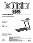
Owner’s Manual
215-00132
11/06 Rev A
KPS-CC
Cable Crossover
Table of Contents
Before You Start
3
Important Safety Information
4
Assembly
5-12
Parts List
13
Exploded View
14
Warranty Information
15
Before You Start
THANK YOU for making this unit a part of your exercise program.
Keys Fitness assures the very best in value, appearance, durability
and biomechanics.
This manual will guide you through the assembly process. If at
any time you are having trouble with the assembly or use of this product, then
please contact us at our Keys Fitness Help line. We have trained service technicians on site to take care of you, our valued customer.
REGISTRATION CARD
To avoid unnecessary delays in warranty parts and to ensure that a permanent
record of your purchase is on file with our company, be sure to send in the warranty registration card or register on-line at www.keysfitness.com within 10 days
of purchase.
KEYS FITNESS Series
Model: KF-CC
QUESTIONS?
CALL
1-888-340-0482
M on d a y - F r i d a y
8 : 3 0 - 5 : 3 0 C e n tr a l T i m e
When calling please have the following product information available:
Model Name :
Date Mfg.:
PO # :
Serial #:
Model Name Decal Location
Important Safety Information
Prior to assembly, remove components from the box and verify that all the listed parts were
supplied.
NOTE: Hand tighten bolts and nylon nuts until machine is fully assembled.
Read all precautions and instructions in this manual before using this equipment.
WARNING!
efore using this unit or starting any exercise program, consult your
B
physician. This is especially important for persons over the age of
35 and/or persons with pre-existing health problems. Keys Fitness
Products LP assumes no responsibility for personal injury or property
damage sustained by or through the use of this product.
It is the owner’s responsibility to ensure that all users of this unit have
read the Owner’s Manual and are familiar with safety information and
precautions.
SAFETY PRECAUTIONS
•T
his unit should only be used on a level surface and is intended for
indoor use only. Keys Fitness recommends an equipment mat be
placed under the unit to protect the floor or carpet and for easier
cleaning.
•W
ear comfortable, good-quality walking or running shoes and appropriate clothing. Do not use this unit with bare feet, sandals, socks or
stockings!
•A
lways examine your unit before using to ensure all parts are in
working order.
• Do not leave children unsupervised near or on the unit.
•S
ervice to your unit should only be performed by an authorized
service representative, unless authorized and/or instructed by a
Keys Fitness technician. Failure to follow these instructions will void
the warranty.
Assembly
NOTE: Hand tighten bolts and nylon nuts until machine is fully assembled.
Step 1
Attach Middle Base (2) to Left Rear Upright (4) and Inner Base (1) using Bolts (42), Washers
(53) and Nylon Lock Nuts (54).
NOTE: Hand tighten bolts and nylon nuts until machine is fully assembled.
Step 2
Attach Middle Base (2) to Right Rear Upright (3) and Inner Base (1) using Bolts (42), Washers
(53) and Nylon Lock Nuts (54).
Assembly
NOTE: Hand tighten bolts and nylon nuts until machine is fully assembled.
Step 3
NOTE: Before completing any other steps, you should position noth ends of the unit 12 ft
apart from each other to accommodate the Cross Tube (11). This will keep you from having to
move the unit once it is loaded with weights.
Slide Weight Bumpers (38) and Guide Rods (9) onto holes of Middle Base (2).
Slide quantity 9 of the 10 lb. plates (33) onto guide rods. Then slide quantity 10 of the 5 lb.
plates (34) onto guide rods.
Slide Top Plate (32) onto top of weight stack. Insert Weight Pin (35)
Repeat STEP 3 on other side.
Assembly
NOTE: Hand tighten bolts and nylon nuts until machine is fully assembled.
Step 4
Insert Left Slide Frame (6) onto Slide Guide Tube (5) as shown and lock into one of the holes
in tube.
Attach Slide Guide Tube (5) to Inner Base (1) with Bolt (41), Washers (53) and Nylon Lock Nut
(54).
Slide Top Frame (8) onto Guide Rods (9) and Slide Guide Tube (5) and connect as shown, using
Bolts (46), Washers (53), Nylon Locknut (54) and Bolt (44).
Secure Top Frame (8) to Left Upright (4) using Bolts (40), Washers (53) and Nylon Lock Nuts
(54).
Assembly
NOTE: Hand tighten bolts and nylon nuts until machine is fully assembled.
Step 5
Insert Right Slide Frame (7) onto Slide Guide Tube (5) as shown and lock into one of the holes
in tube.
Attach Slide Guide Tube (5) to Inner Base (1) with Bolt (41), Washers (53) and Nylon Lock Nut
(54).
Slide Top Frame (8) onto Guide Rods (9) and Slide Guide Tube (5) and connect as shown, using
Bolts (46), Washers (53), Nylon Locknut (54), and Bolt (41).
Secure Top Frame (8) to Right Upright (3) using Bolts (40), Washers (53) and Nylon Lock Nuts
(54).
Assembly
NOTE: Hand tighten bolts and nylon nuts until machine is fully assembled.
Step 6
Slide Top Cross Tube (11) into both sides of the Top Frame (8) and secure as shown, using
Bolts (41), Washers (53) and Nylon Lock Nuts (54). Note: two people will be needed to complete this step safely.
Connect Chin-Up Handle (16) to Top Cross Tube (11) using Bolts (48), Washers (53) and Nylon
Lock Nuts (54).
10
Assembly
NOTE: Hand tighten bolts and nylon nuts until machine is fully assembled.
Step 7
Secure Big Pulleys (20) to Double Pulley Bracket (13) using Bolts (43), Washers (53), and
Nylon Lock Nuts (54).
Secure Double Pulley Bracket (13) to Left Slide Frame (6) using Bolt (47), Small Bushings (36)
and Nylon Lock Nuts (54).
Secure Big Pulleys (20) to unit using Bolts (40), Washers (53) and Nylon Lock Nuts (54).
Attach Small Pulleys (21) to unit using Bolts (40), Washers (53), Pulley Spacers (37) used on
the two pulleys on the Top Frame (8), and Nylon Lock Nuts (54).
Insert Cable (15) through the pulleys in the Double Pulley Bracket (13) and install as shown.
Secure cable end to Left Slide Frame (6) using Bolt (44), Washers (53) and Nylon Lock Nuts
(54).
Repeat for Right Side.
11
Assembly
NOTE: Hand tighten bolts and nylon nuts until machine is fully assembled.
Step 8
Attach Handle (10) to each side of frame and secure with Bolts (39) and Washers (51).
TIGHTEN ALL BOLTS AND NUTS before continuing!
Once all bolts and nuts are tightened, then attach Weight Shrouds (12,62,63) with Allen Bolts
(49) and Washers (52).
12
Parts List
KF-CC Parts list Rev A
Ref #
Part #
description
Qty
1
3-010
BASE, INNER KF-CC
3-0103
BASE, MIDDLE KF-CC
3
3-0104
UPRIGHT, REAR RIGHT KF-CC
1
4
3-0105
UPRIGHT, LEFT REAR KF-CC
1
5
3-010
TUBE, SLIDE GUIDE KF-CC
19-000
LEFT SLIDE FRAME KPS-CC
1
19-00059
RIGHT SLIDE FRAME KPS-CC
1
8
19-0009
FRAME, TOP KF-CC
9
3-0085
GUIDE ROD, KPS-CC
4
10
19-0008
HANDLE, KF-CC
11
3-0101
TUBE, TOP CROSS KF-CC
1
1
3-0095
WEIGHT SHROUD,TOP KF-180
4
13
19-00054
DOUBLE PULLEY BRACKET KPS-CC, KPS-SCC
14
19-0004
SWIVEL PULLEY BLOCK KPS-CC, KPS-SCC
15
9-0001
CABLE KPS-CC P15
1
19-000
HANDLE, CHIN UP KF-CC
1
1
19-00
SELECTOR ROD INRAY-GYMS
18
0-00048
JAM NUT 1/"
18
0-00048
JAM NUT 1/"
19
10-005
POP PIN (LOCKING), KF-45/KF-AAB
0
3-008
BIG PULLEY 4.5"
1
3-0031
SMALL PULLEY, KPS-CC/CG/LATA/SCC
10-0001
HAND STRAP INRAY GYM
3
10-00059
ANKLE STRAP INRAY GYM
4
0-00391
SQUARE PLUG, 50.8 KF SERIES
8
5
0-00035
PLASTIC SLEEVE, 3.5X50.8
4
0-0010
PLUG 3 - KPS
4
0-00004
PLUG 5
4
8
0-00459
GRIP, KPS-CC 30X4X0
9
0-00055
GRIPS KPS-CC 30x4x500
30
0-00054
LONG GRIPS 30X4X59
31
10-00008
GEAR HOOK, KPS, 10-00008
3
3-00031
TOP PLATE KPS-GYM
35
10-00004
WEIGHT PIN
3
0-0003
SMALL BUSHING KPS-CG
4
3
0-0003
PULLEY SPACER
8
38
0-000
WEIGHT BUMPER KPS
4
39
0-001
SCREW, BUTTON HD SOCKET CAP M1X3
4
40
0-004
BUTTON HEAD SOCKET CAP SCREW M10X5
8
41
0-005
SCREW, BUTTON HEAD SOCKET CAP M10X5
8
4
0-0034
SCREW, M10X80 BUTTON HEAD SOCKET CAP
4
43
0-004
SCREW, BUTTON HEAD SOCKET CAP M10X50
10
44
0-003
SCREW, BUTTON HEAD SOCKET CAP M10X35
45
0-00
SCREW, BUTTON HD SOCKET CAP M10X55
4
0-00
SCREW, BUTTON HEAD SOCKET CAP M10X5
4
4
0-003
SCREW, BUTTON HD SOCKET M10X140
48
0-004
SCREW, BUTTON HD SOCKET CAP M10X135
49
0-005
SCREW, BUTTON HD SOCKET CAP M8X10
50
0-0011
SCREW, M1*35
51
0-001
WASHER, 13*4*1.5
5
0-0013
WASHER, 9**
1
53
0-00093
WASHER, 10
54
0-00091
NYLON NUT, M10
38
55
0-001
ALLEN WRENCH S
5
0-00394
PLUG, 50.8X. KF SERIES
5
0-003
SCREW, M8X5 BUTTON HEAD SOCKET CAP
58
0-000
ALLEN WRENCH, S=5
1
59
0-0049
SLEEVE, EZ GLIDE 1 50.8 KF-LATM/KF-CC
8
0
0-0040
SLEEVE, EZ GLIDE 50.8 KF-LATM
8
1
0-001
ALLEN WRENCH, S=8
1
3-00958
WEIGHT SHROUD, MIDDLE KF-180
4
3
3-00959
WEIGHT SHROUD, BOTTOM KF-180
4
4
0-00
SMALL SPACER, KF-180
3
5
0-00
SCREW, BUTTON HD SOC CAP MX18
3
0-0003
NYLON NUT M
3
0-00
WASHER, .X1X1.
4
8
0-001
Allen Wrench S4
10
1
4
1
4
1
1
13
63
62
64
66
12
14
51
10
65
67
45
24
60
52
2
9
59
43
54
21
43 54
4
30
39
50
14
42
49
43
38
57
18
21
44
25
47
46
27
46 49
28
52
8
40
53 56
53
1
21
37
40
5
35
41
21
6 43
41
36
41
21
53
53
41
20
53
13
15
20
23
22
54
53
53
29
31
54
48
31
54
16
29
48
26
26
7
11
3
32
19
20
Exploded View
Warranty Information
KEYS FITNESS PRODUCTS, L.P.
LIFETIME WARRANTY
This Warranty applies in the United States and Canada to products manufactured or distributed by Keys Fitness Products, LP (“Keys”) under the KEYS brand name. The warranty is nontransferable and valid only to the original purchaser.
Keys warrants that the Product you have purchased for non-commercial, personal, family, or
household use from Keys or from an authorized Keys reseller is free from defects in materials or workmanship under normal use during the warranty period. Your sales receipt, showing
the date of purchase of the Product, is your proof of purchase. This warranty only extends
to you, the original purchaser. It is not transferable to anyone who subsequently purchases
or acquires the Product from you. This Warranty becomes VALID ONLY if the product is purchased through a Keys Fitness authorized dealer unless otherwise authorized by Keys Fitness in writing and must be
assembled / installed according to the instructions included with the Product.
In a light institutional setting, Keys will extend a one year limited warranty to the original purchaser.
During the warranty period Keys will repair or replace (at Keys' option) the product if it becomes defective, malfunctions, or otherwise fails to conform with this Warranty under normal use. In repairing the Product, Keys may replace
defective parts with new or, at the option of Keys, serviceable used parts that are equivalent to new parts in performance. All exchanged parts and Products replaced under this warranty will become the property of Keys. Keys
reserves the right to change manufacturers of any part to cover any existing warranty.
This warranty DOES NOT COVER shipping charges, export taxes, custom duties and taxes, or any other charges
associated with transportation of the parts or Product. To obtain warranty service, you must contact a Keys authorized retailer, service technician or Keys Fitness at our phone number located in this manual. Any parts determined
to be defective must be returned to Keys to obtain warranty service. You must prepay any shipping charges, export
taxes, custom duties and taxes, or any other charges associated with transportation of the parts or Product. In addition, you are responsible for insuring any parts or Product shipped or returned. You assume the risk of loss during
shipment. You must present Keys with proof-of-purchase documents (including the date of purchase). Any evidence
of alteration, erasure or forgery of proof-of-purchase documents will be cause to void this Warranty.
This Warranty does not extend to any product not purchased from Keys or from an authorized Keys reseller. This
Limited Warranty does not extend to any Product that has been damaged or rendered defective; (a) as a result of
accident, misuse, or abuse; (b) by the use of parts not manufactured or sold by Keys; (c) by modification of the
Product (d) normal wear and tear; (e) operation on incorrect power supplies; or (f) as a result of service by anyone other than Keys, or an authorized Keys warranty service provider. Product on which the serial number has been
defaced or removed is not eligible for warranty service. Should any Product submitted for warranty service be found
ineligible, an estimate of repair cost will be furnished and the repair will be made if requested by you upon Keys'
receipt of payment or acceptable arrangements for payment.
EXCEPT AS EXPRESSLY SET FORTH IN THIS WARRANTY, KEYS MAKES NO OTHER WARRANTIES, EXPRESSED
OR IMPLIED, INCLUDING ANY IMPLIED WARRANTIES OF MERCHANTABILITY AND FITNESS FOR A PARTICULAR
PURPOSE. KEYS EXPRESSLY DISCLAIMS ALL WARRANTIES NOT STATED IN THIS LIMITED WARRANTY. ANY IMPLIED
WARRANTIES THAT MAY BE IMPOSED BY LAW ARE LIMITED TO THE TERMS OF THIS LIMITED WARRANTY. NEITHER
KEYS NOR ANY OF ITS AFFILIATES SHALL BE RESPONSIBLE FOR INCIDENTAL OR CONSEQUENTIAL DAMAGES.
SOME STATES DO NOT ALLOW LIMITATIONS ON HOW LONG AN IMPLIED WARRANTY LASTS OR THE EXCLUSION
OR LIMITATION OF INCIDENTAL OR CONSEQUENTIAL DAMAGES, SO THE ABOVE LIMITATIONS OR EXCLUSION MAY
NOT APPLY TO YOU. This Limited Warranty gives you specific legal rights and you may also have other rights that
may vary from state to state. This is the only express warranty applicable to Keys-branded products. Keys neither
assumes nor authorizes anyone to assume for it any other express warranty.
PLEASE SEND IN THE INCLUDED WARRANTY CARD OR REGISTER ON-LINE AT www.keysfitness.com WITHIN TEN
(10) DAYS OF PURCHASE TO REGISTER YOUR UNIT WITH KEYS FITNESS PRODUCTS, LP. MAIL WARRANTY CARD
TO: KEYS FITNESS PRODUCTS, PO BOX 551239, DALLAS, TX 75355
15
Keys Fitness Products, L.P.
4009 Distribution Drive, Suite 250
Garland, Texas 75041
Customer Service: 1-888-340-0482