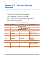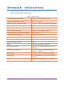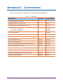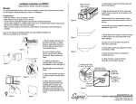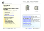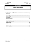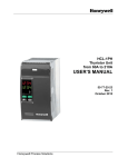
1
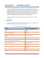
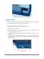
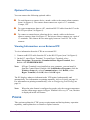
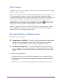
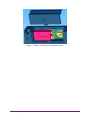
Vision Temperature
Recorder
User’s Guide
Limited Warranty
Supco International Ltd hereby warrants that it will repair or replace, at its option, any part of the
VISION TEMPERATURE RECORDER or any of its accessories, which proves defective by reason
of improper workmanship or material, free of charge for parts and labor, for a period of ONE YEAR
from the date of original purchase by the buyer. This warranty does not apply if, in the sole opinion
of Supco International Ltd, the VISION TEMPERATURE RECORDER, or any of its accessories,
has been intentionally or accidentally damaged due to misuse, neglect, or improper packing,
shipping, modification or servicing, by other than Supco International Ltd, or personnel authorized
by Supco International Ltd. For information on how to obtain service under this warranty, contact
the dealer where your VISION TEMPERATURE RECORDER was purchased or contact Supco
International Ltd at the address printed below:
SUPCO International Ltd
P.O. Box 8047
Haumanut Street 3
Netanya 42180
Israel
Telephone: 972-9-865-4101
Fax: 972-9-865-9111
[email protected]
Liability Disclaimer Statement
Supco International Ltd (hereafter known as Supco) makes no warranty, representation, or guarantee
regarding the suitability of its products for any particular purpose, nor does Supco assume any
liability arising out of the application or use of any product, and specifically disclaims any and all
liability, including without limitation consequential or incidental damages.
Supco products are not designed, intended, or authorized for use as components in life support
systems, or for any other application in which the failure of the Supco product could create a
situation where personal injury or death or significant financial loss may occur.
Should any person or persons purchase or use Supco products for any such unintended or
unauthorized application, that person or persons shall indemnify and hold Supco and its officers,
employees, affiliates, and distributors harmless against all claims, costs, damages, and expenses, and
reasonable attorney fees arising out of, directly or indirectly, any claim of personal injury, death or
financial loss associated with such unintended or unauthorized use, even if such claim alleges that
Supco was negligent regarding the design or manufacture of the product in question.
TABLE OF CONTENTS
Chapter 1
Introduction ........................................................... 1
Features...............................................................................................1
Description..........................................................................................2
Chapter 2
Installation .............................................................. 4
Package Contents................................................................................4
Installation Options.............................................................................4
Bracket Mounting ........................................................................5
Connections ........................................................................................6
Mandatory Connections and Startup...........................................6
Optional Connections..................................................................7
Viewing Information on an External PC .....................................7
Power ..................................................................................................7
Power Source ..............................................................................8
Battery Installation and Replacement .........................................8
Chapter 3
Operation .............................................................. 10
Displaying Temperatures ..................................................................10
Printing .............................................................................................10
Advancing and Changing Printer Paper ............................................11
Alarms ..............................................................................................12
Chapter 4
Configuration........................................................ 13
Online Help.......................................................................................14
Configuring Alarm Settings ..............................................................14
Configuring the Alarm Range....................................................14
Configuring the Alarm Delay ....................................................15
Vision Temperature Recorder
i
Configuring the Alarm Output...................................................15
Configuring the End of Paper Alarm.........................................16
Configuring Print Settings ................................................................16
Configuring Temperature and Date Formats.....................................18
Changing the Time and Date ............................................................18
Changing the Password.....................................................................19
Changing the Device ID....................................................................19
Changing the Temperature Calibration .............................................20
Erasing the Log.................................................................................21
Changing the Sampling Rate.............................................................21
Chapter 5
Troubleshooting.................................................... 22
Appendix A Factory Default Settings ...................................... 23
Appendix B Specifications ........................................................ 25
Appendix C Components .......................................................... 26
Appendix D Menu Structure .................................................... 27
ii
Vision Temperature Recorder
CHAPTER 1
INTRODUCTION
The Vision Temperature Recorder (VTR) records, saves, and prints up to 290
temperature readings at predefined intervals. The VTR produces an alarm whenever
the temperature goes above or below a defined range. The alarm can be produced
immediately when the temperature goes out of the defined range, or after the
temperature remains out of range for a certain period of time. The VTR provides
several printing options, including the ability to send data to an external PC. The
VTR can also send alarms to an external device via a relay contact.
The VTR can monitor, log, and print temperatures of -40°C to +130°C (-40°F to
+266°F), +\- 1°.
FEATURES
Table 1 describes the VTR features, with references to the section and page in this
manual describing how to use or configure the feature.
Table 1: Vision Temperature Recorder Features
FEATURE
FOR FURTHER INFORMATION SEE
Records temperatures at intervals of between one and 90
minutes
Changing the Sampling Rate on
page 21
Produces an alarm if the temperature goes above or
below a predefined range
Configuring the Alarm Range on
page 14
Records and displays temperatures in either Celsius or
Fahrenheit, and date in European or English (American)
format
Configuring Temperature and Date
Formats on page 18
Records and prints 290 readings on request at any time
Printing on page 10
Three printing formats, including graphic or text, and ID
number, time, temperature, and alarm status
Configuring Print Settings on page 16
Audio and visual alarms, including an option for sending
alarms to an external device
Alarms on page 12 and Optional
Connections on page 7
Option to export data to external PC
Viewing Information on an External
PC on page 7
Optional backup battery
Battery Installation and Replacement
on page 8
Waterproof, remote 10 meter sensor
Vision Temperature Recorder
1
DESCRIPTION
Figure 1 shows the front and top of the VTR.
Figure 1: Vision Temperature Recorder - Front/Top View
1.
2.
3.
4.
5.
6.
7.
8.
9.
2
Power switch
RS-232 port
12V DC power jack
Buzzer silent contacts
Temperature sensor input jack
Remote alarm contacts
Paper cover clip
Secure to the bracket
Paper cover
Vision Temperature Recorder
Figure 2 shows the rear and bottom of the VTR.
Figure 2: Vision Temperature Recorder - Rear View
10.
11.
12.
13.
14.
15.
Secure tie hole
Hanging hole
Bracket hanging hole
Batteries cover
Bracket mounting
Buzzer alarm grill
Figure 3 shows the display area of the VTR.
Figure 3: Vision Temperature Recorder - Display Area
Vision Temperature Recorder
3
CHAPTER 2
INSTALLATION
This chapter explains how to install the VTR, and includes the following topics:
▲
▲
▲
▲
Package Contents – Lists the contents of the VTR package.
Installation Options – Describes the possible ways to install the VTR, and
describes how to attach the VTR to a wall bracket.
Connections – Describes the mandatory and optional cable connections,
including instructions on how to start the VTR.
Power – Describes the VTR’s power requirements and backup battery
operation capability, and explains how to install or replace batteries.
PACKAGE CONTENTS
The VTR package should include the following components:
Table 2: Package Contents
DESCRIPTION
QUANTITY
PART NUMBER
VTR unit with one temperature channel
1
10 m temperature sensor cord (33 feet)
1
VKT
Thermal paper roll, 2 inches wide, 40 meters
long (131 feet)
2 (1 installed)
143156
12V DC power adaptor, 2 Amps - US (120V)
OR
12V DC power adaptor, 2 Amps - EU (230V)
1
061008
3.6V Lithium battery
1 (installed)
CR2032
Hanging bracket
1
143158
User’s Guide
1
123248
061009
INSTALLATION OPTIONS
You can use the VTR as a standalone unit or attach it to a wall. There are two ways
to attach the VTR to a wall:
4
Vision Temperature Recorder
▲
▲
Direct Mounting – Attach the VTR directly to the wall.
Bracket Mounting – Attach the VTR bracket to the wall, and hang the VTR
on the bracket, as described below.
Bracket Mounting
To attach the VTR to the wall using the bracket:
1. Mount the VTR bracket to the wall with three screws, as shown in Figure 4.
Hooks
Figure 4: Bracket Mounting
Note:
Make sure to leave enough space on the left to operate the main switch
and connect all the other cables mentioned in Connections on page 6.
2. Hang the VTR on the two hooks on the mounted bracket, as shown in Figure 4.
3. Open the paper cover by pushing the two cover clips (item 7 in Figure 1) to the
inside and pulling the cover out.
4. Fasten one screw through the hole under the paper roll to secure the VTR to the
bracket, as shown in Figure 5.
5. Return the paper cover to its place.
Vision Temperature Recorder
5
Figure 5: Securing the Unit to the Bracket
CONNECTIONS
This section describes the cables you must connect in order to use the VTR, as well
as cables you can attach in order to use optional features.
Mandatory Connections and Startup
To connect and start up the VTR:
1. Plug the AC adaptor into the power supply and connect the 12V DC power cord
to the power jack (item 3 in Figure 6).
2. Connect the temperature sensor cord to the temperature sensor input jack (item 5
in Figure 6).
3. Switch the power switch to the On position (item 1 in Figure 6). The Power and
Sensor LEDs turn green. After a few moments, the temperature should appear in
the display area.
Figure 6: Connections
6
Vision Temperature Recorder
Optional Connections
You can connect the following optional cables:
▲
▲
▲
To send alarms to a remote device, attach a cable to the remote alarm contacts
(item 6 in Figure 6). The remote alarm contacts are a pair of ¼” terminals,
1 Amps, 12V.
To export temperature data to a PC, attach an RS-232 cable from the PC to the
RS-232 port (item 2 in Figure 6).
To connect a remote buzzer silencing device, attach a cable to the buzzer
silencer contacts (item 4 in Figure 6). The buzzer silencer contacts are a pair of
¼” terminals. The silencer device must apply between 5 and 12V DC to the
contacts.
Viewing Information on an External PC
To view information from the VTR on an external PC:
1. Connect an RS-232 cable from the PC to the RS-232 port (item 2 in Figure 6).
2. On the PC, open Hyper Terminal. To open Hyper Terminal, select
Start>Programs>Accessories>Communications>HyperTerminal, then
double-click HYPERTRM.EXE.
Note:
If Hyper Terminal is not installed on your computer, you can install it
from the Control Panel. Double-click Add/Remove Programs, click the
Windows Setup tab, select Communications, click Details, select
Hyper Terminal, click OK, then click OK again.
The PC displays whatever information the VTR prints, both manually and
automatically. For information on printing manually, refer to Printing on page 10.
For information on printing automatically, refer to Configuring Print Settings on
page 16.
Note:
When the print format is configured as graph, only the current temperature
and the alarm range appear in Hyper Terminal. On every 12th row, the data
is displayed in full text format.
POWER
This section explains the VTR’s power requirements and backup battery operation
capability, and explains how to install or replace batteries.
Vision Temperature Recorder
7
Power Source
The VTR uses a 12V power supply. When the VTR is using the main power supply,
the Power LED is lit green.
In the event of a power failure, or if the working temperature goes over 65°C, the
VTR automatically switches over to a 9V backup battery (if installed). When
operating in backup mode, the VTR logs temperature measurements to memory, but
does not print. The Power LED blinks, and the display area shows the current
temperature every 30 seconds for two seconds. You can also display the current
. With a new 9V
temperature for two seconds at a time manually by pressing
battery, the VTR can operate in backup mode for 60 hours.
When the main power returns, the Power LED goes on without blinking, and the
printer prints the temperature measurements that were recorded but not printed
when the VTR was operating in backup mode.
Battery Installation and Replacement
The VTR uses two batteries:
▲
▲
Lithium battery (CR2032) – Used for saving logging data and configuration
settings, and for running the real-time clock. After replacing the Lithium
battery, you should check and reset the VTR configuration settings.
9V alkaline backup battery – Used for backup operation (refer to Power
Source on page 8). This battery is optional, and is not included with the VTR
package. When the Low Batt LED blinks, you should replace the 9V backup
battery.
To change or install batteries:
1. Push and slide the cover of the battery compartment out, as shown in Figure 7.
2. Install the batteries as indicated, according to the polarity marks in the battery
compartment.
3. Position the cover over the battery compartment and snap it back into place.
8
Vision Temperature Recorder
Figure 7: Battery Installation and Replacement
Vision Temperature Recorder
9
CHAPTER 3
OPERATION
This chapter explains how to operate the VTR, and includes the following topics:
▲
▲
▲
▲
Displaying Temperatures
Printing
Advancing and Changing Printer Paper
Alarms
DISPLAYING TEMPERATURES
When the VTR is on, it displays the current temperature. You can also display the
maximum and minimum measured temperatures in the VTR’s memory by pressing
and
. The time period this covers depends on the sampling rate. For
example, if the sampling rate is one minute, the VTR’s memory includes up to 290
minutes of temperature data. If the sampling rate is every 10 minutes, the VTR’s
memory includes up to 2,900 minutes of data.
▲
▲
Press
to display the lowest temperature in memory. Press
again to
display the highest temperature in memory, AdJ (for adjusting parameters),
and to return to the current temperature. After three seconds, the display
automatically returns to the current temperature.
Press
to display AdJ (for adjusting parameters). Press
again to
display the highest temperature in memory, the lowest temperature in memory,
and to return to the current temperature. After three seconds, the display
automatically returns to the current temperature.
Note:
You can configure the VTR to display temperatures in either Celsius or
Fahrenheit. Refer to Configuring Temperature and Date Formats on
page 18.
PRINTING
The VTR can be configured to print temperatures automatically at defined intervals.
For a description of the available print modes and instructions on configuring the
print settings, refer to Configuring Print Settings on page 16.
10
Vision Temperature Recorder
You can also print manually or send a list of measurements in memory to a PC. To
. SEnd appears in the
send a list of measurements to the printer or a PC, press
display area.
▲
▲
▲
To print, press
.
To send a list of measurements to a PC, press
.
If you do not press either button within three seconds, the display automatically
returns to the current temperature.
The VTR prints or sends a list of all saved measurements in whatever print mode is
currently configured. If the VTR is also configured to print or send measurements
automatically, then when the printing is finished, the VTR prints or sends all
measurements that were recorded during the manual printing or sending operation.
Note:
When you send a report to a PC, all data is sent within ten seconds.
. The printout or report displays the message
To manually stop printing, press
MEMORY REPORT STOPPED BY USER.
ADVANCING AND CHANGING PRINTER PAPER
The VTR uses thermal printing paper to print temperature readings. This type of
paper uses heat, rather than ink, to print. The VTR’s printer does not print on
ordinary paper. When ordering replacement paper rolls, make sure to order thermal
paper.
When a red line appears on the side of the paper, this indicates that the paper roll is
almost finished. You should replace the paper roll before it reaches the end, so that
the printer will not stop.
To replace the paper roll:
1. Press
Note:
two or three times to advance the paper.
The
button does not work unless the printer is set for automatic
printing. Refer to Configuring Print Settings on page 16.
2. Tear out the latest printed report.
3. Open the paper cover and remove the leftover paper roll. The alarm buzzer will
sound, and the Out of Paper LED will blink.
4. Straighten the edge of the new paper roll with a scissors.
Vision Temperature Recorder
11
5. Place the new paper roll in the paper compartment and push the edge of the
paper straight through the printer.
to advance the paper through the printer. After installing the new
6. Press
roll, the alarm buzzer and the Out of Paper LED should go off.
ALARMS
The VTR has the following alarm indicators:
▲
▲
▲
Buzzer – Some alarms trigger an internal buzzer. You can silence the buzzer
by pressing
. You can also configure the VTR so that the buzzer does not
go off. Refer to Configuring the Alarm Output on page 15.
LEDs – The four LEDs to the left of the display area indicate various alarms,
as described below. The top LED indicates that the VTR’s power is on.
Relay Contact to External Device – You can connect the VTR to an external
device and configure the VTR to send alarms to the external device via a relay
contact. Refer to Configuring the Alarm Output on page 15.
The following events trigger an alarm:
▲
▲
▲
▲
12
Paper jam – If there is a paper jam, the Out of Paper LED lights.
Disconnected Temperature Sensor – If the temperature sensor is
disconnected from the device, the display area shows the message nOS and the
Alarm LED lights.
Alarm Range – If the measured temperature goes outside the maximum or
minimum defined temperature range for a consecutive period of time equal to
the defined alarm delay period (if any), an alarm is sent. The internal buzzer
sounds (if enabled), and an alarm is sent to an external device via the relay
contact (if enabled). In addition, the Alarm LED lights. For instructions on
configuring the buzzer and relay contact to respond to Alarm Range alarms,
refer to Configuring the Alarm Output on page 15.
End of Paper – If the printer paper runs out, the internal buzzer sounds (if
enabled), and an alarm is sent to an external device via the relay contact (if
enabled). In addition, the Alarm LED lights. For instructions on configuring
the buzzer and relay contact to respond to Out of Paper alarms, refer to
Configuring the End of Paper Alarm on page 16.
Vision Temperature Recorder
CHAPTER 4
CONFIGURATION
This chapter explains how to configure the VTR. To configure VTR parameters,
you must enter a password. The default password is
. For
instructions on changing your password, refer to Changing the Password on
page 19.
To change the VTR configuration:
1. Press
or
2. Press
. PASS appears in the display area.
until AdJ appears in the display area.
3. Enter your password. ALr appears in the display area. ALr allows you to
change the alarm settings.
4. The VTR has nine root menu items. To scroll through the root menu items, press
. To scroll through the root menu items in reverse order, press
. The
following are the root menu items:
∇
ALr – Alarm configuration
∇
Prn – Printing configuration
∇
SCAL –Temperature and date format configuration
∇
CLoC – Date and time configuration
∇
ChPA – Password configuration
∇
SIdn – ID number configuration
∇
CALb – Temperature calibration
∇
Lo9r – Erasing the log
∇
SAPr – Sampling rate configuration
Note:
For a full diagram of the VTR menu tree, refer to Appendix D, Menu
Structure on page 27. For a list of the default factory settings, refer to
Appendix A, Factory Default Settings on page 23.
5. When you reach the root menu item that you want, press
sub-menu item appears.
6. When you have finished configuring an item, you must press
configuration changes.
Vision Temperature Recorder
. The first
to save the
13
ONLINE HELP
{Question - which button do you press for HELP?}
Notes:
You cannot print online help unless the printer is set for automatic
printing. Refer to Configuring Print Settings on page 16.
If the VTR is configured to send output to an external PC, help messages
will also be sent to the external PC.
CONFIGURING ALARM SETTINGS
To configure alarm settings, display the ALr root menu. From the ALr root menu,
you can configure the following alarm settings:
▲
▲
▲
▲
Alarm Range (ALS) – Allows you to define a temperature range. When the
current temperature is outside of this range, the VTR sends an alarm.
Alarm Delay (ALdl) – Allows you to define an alarm delay. If the current
temperature goes out of the defined temperature range, the VTR does not send
an alarm until the temperature remains outside of the range for the length of
time defined by the Alarm Delay parameter.
Alarm Output (ALO) – Allows you to define whether or not the VTR’s
internal alarm sounds when an alarm is sent, and whether or not alarms are sent
to an external device.
End of Paper Alarm (EOFP) – Allows you to define whether or not the
VTR’s internal alarm sounds, and whether or not alarms are sent to an external
device, when the paper runs out or jams.
Configuring the Alarm Range
To configure the high and low temperatures that will trigger an alarm:
1. From the ALr menu, press
. ALS appears.
2. Press
. LoA1 appears. Press
or
to set the minimum temperature.
Temperatures below this temperature will trigger an alarm.
3. Press
. HIA1 appears. Press
or
to set the maximum temperature.
Temperatures above this temperature will trigger an alarm.
4. Press
14
. The changes are saved and ALS appears.
Vision Temperature Recorder
∇
To change other alarm settings, press
alarm menu items.
∇
To go to another root menu item, press
to display the other root menu items.
∇
To exit configuration and display the current temperature, press
twice.
or
to display the other
again, then press
or
Configuring the Alarm Delay
To configure the alarm delay:
1. From the ALr menu, press
. ALS appears.
2. Press
. ALdl appears.
3. Press
. The current alarm delay setting appears.
4. Press
or
to scroll among the possible alarm delay values: n0 (no
delay), 10 (minutes), 30 (minutes), 1 h (1 hour), and 2 h (2 hours). When the
value you want to select appears, press
. ALdl appears.
5. Press
. The changes are saved and ALr appears.
6. Press
again to exit configuration and display the current temperature.
Configuring the Alarm Output
To configure the alarm output:
1. From the ALr menu, press
. ALS appears.
2. Press
or
3. Press
. The current alarm buzzer setting appears:
twice. ALO appears.
∇
buOn – The internal buzzer will sound when there is an alarm.
∇
buOF – The internal buzzer will not sound when there is an alarm.
. To change the setting, press
or
4. To keep the current setting, press
to toggle the setting, then press
. The current external device setting
appears:
∇
CoOn – A signal is sent to the external device when there is an alarm.
∇
CoOF – A signal is not sent to the external device when there is an
alarm.
5. To keep the current setting, press
. To change the setting, press
to toggle the setting, then press
. ALO appears.
Vision Temperature Recorder
or
15
6. Press
. The changes are saved and ALr appears.
7. Press
again to exit configuration and display the current temperature.
Configuring the End of Paper Alarm
To configure the End of Paper alarm output:
1. From the ALr menu, press
. ALS appears.
2. Press
. EOFP appears.
3. Press
. The current End of Paper alarm buzzer setting appears:
∇
buOn – The internal alarm sounds when the printer is out of paper or
jammed.
∇
buOF – The internal alarm does not sound when the printer is out of
paper or jammed.
4. To keep the current setting, press
. To change the setting, press the
or
button to toggle the setting, then press
. The current End of Paper
external device setting appears:
∇
CoOn – An alarm is sent to the external device when the printer is out of
paper or jammed.
∇
CoOF – An alarm is not sent to the external device when the printer is
out of paper or jammed.
5. To keep the current setting, press
. To change the setting, press
to toggle the setting, then press
. EOFP appears.
or
6. Press
. The changes are saved and ALr appears.
7. Press
again to exit configuration and display the current temperature.
CONFIGURING PRINT SETTINGS
To configure print settings, display the Prn root menu. From the Prn root menu,
you can configure the following print settings:
▲
▲
16
Print Format – Allows you to choose from among three print formats. Both
the VTR printer output and the external PC output will use the selected format.
Printer – Allows you to define whether or not the VTR automatically prints
temperature readings. When the printer is set to print automatically, the VTR
prints each temperature reading that it measures, at the defined measurement
intervals. Refer to Changing the Sampling Rate on page 21.
Vision Temperature Recorder
▲
PC Output – Allows you to define whether or not the VTR sends temperature
readings to an external PC.
To configure print settings:
1. From the Prn menu, press
∇
. The current print format appears:
LChr – The VTR prints and sends output to an external PC using a large
character format. Each temperature record includes the following
information: Date, time, and temperature. The following is an example of
a temperature record in large character format:
29 15:32 25.0C
In this example, the date is the 29th of the current month, the time is
15:32 (3:32 p.m.), and the temperature is 25.0°C
∇
SChr – The VTR prints and sends output to an external PC using a small
character format. Each temperature record includes the following
information: ID of the unit recording the measurement, time, date, and
temperature. The following is an example of a temperature record in
small character format:
INRAY 12345 29/04/04 15:32 25.0C
In this example, the ID of the VTR unit is INRAY 12345 (refer to
Changing the Device ID on page 19), the date is April 29, 2004 (refer to
Changing the Time and Date on page 18), the time is 15:32 (3:32 p.m.),
and the temperature is 25.0°C.
∇
Note:
9rAP – The VTR prints in a graph format. The graph format prints
temperature measurements in the form of a curved graph. Every
temperature value is printed next to the relevant graph point. The
minimum and maximum temperature thresholds are shown as separate
striped lines, and the temperature range values are printed in text every
12th row. If temperature range alarms are enabled, the letter A appears
next to any line in which the temperature is outside of the defined
temperature range. In every 12th row, full information is printed in large
character format.
When information is printed to an external PC in graph format, the current
temperature and the alarm range are printed, but the graph itself is not
printed.
2. To keep the current setting, press
. To change the setting, press
or
to toggle the setting, then press
. The current printer setting appears:
∇
PrOn – The VTR printer prints temperature records automatically at the
defined measurement intervals.
∇
PrOF – The VTR printer does not print temperature records unless you
request a printout manually. Refer to Printing on page 10.
Vision Temperature Recorder
17
3. To keep the current setting, press
. To change the setting, press
or
to toggle the setting, then press
. The current PC output setting
appears:
∇
PCOn – The VTR sends temperature records to an external PC
automatically at the defined measurement intervals.
∇
PCOF – The VTR printer does not send temperature records unless you
request it to send output manually. Refer to Printing on page 10.
4. To keep the current setting, press
. To change the setting, press
to toggle the setting, then press
. Prn appears.
or
5. Press
to save your changes, exit configuration, and display the current
temperature.
CONFIGURING TEMPERATURE AND DATE FORMATS
To configure the format in which the VTR displays temperatures (Celsius or
Fahrenheit) and dates (European or American):
1. Display the SCAL root menu.
2. From the SCAL menu, press
∇
F d9 – Fahrenheit
∇
C d9 – Celsius
. The current temperature format appears:
3. To keep the current setting, press
. To change the setting, press
or
to toggle the setting, then press
. The current date format appears:
∇
EndA – English (American) date format (mm/dd/yy)
∇
EudA – European date format (dd/mm/yy)
. To change the setting, press
4. To keep the current setting, press
to toggle the setting, then press
. SCAL appears.
or
5. Press
to save your changes, exit configuration, and display the current
temperature.
CHANGING THE TIME AND DATE
To change the time and date:
1. Display the CLoC root menu.
2. From the CLoC menu, press
Note:
18
. SdAY appears.
To keep the current date and change the time, press
or
to toggle
the setting to Shr, then follow the instructions starting at number 4.
Vision Temperature Recorder
3. To change the date, press
. The current month appears in numerical format
or
to change the setting,
(01 = January, 02 = February, etc.). Press
then press
. The current day of the month appears. Press
or
to
. The last two numbers of the year appear.
change the setting, then press
Press
or
to change the setting, then press
. Shr appears.
4. To change the time, press
when Shr is displayed. The current hour appears.
Press
or
to change the setting, then press
. The current time in
or
to change the setting, then press
.
minutes appears. Press
CLoC appears.
5. Press
to save your changes, exit configuration, and display the current
temperature.
CHANGING THE PASSWORD
To change the VTR password:
1. Display the ChPA root menu.
2. From the ChPA menu, press
. PASS appears.
3. Enter a sequence of four keys. PASS appears again.
4. Enter the same sequence of four keys. If the second sequence is the same as the
first sequence, ChPA appears. If it is not, PASS appears again, and you must
repeat steps three and four.
5. Press
to save the new password, exit configuration, and display the current
temperature.
CHANGING THE DEVICE ID
The VTR has a device ID that appears in temperature reports. The purpose of the
device ID is to identify the device producing printouts and reports when printouts
and reports are being collected from more than one device.
The device ID consists of 11 alphanumeric characters. You can change each
character individually by entering a numerical code of one or two numbers. Table 3
shows the code for setting the device ID.
Vision Temperature Recorder
19
Table 3: Numerical Code for Setting Device ID
CHR.
CODE
CHR.
CODE
CHR.
CODE
CHR.
CODE
CHR.
CODE
0
0
8
8
F
16
N
24
V
32
1
1
9
9
2
2
3
3
4
G
17
O
25
W
33
10
H
18
P
26
X
34
A
11
I
19
Q
27
Y
35
4
B
12
J
20
R
28
Z
36
5
5
C
13
K
21
S
29
-
37
6
6
D
14
L
22
T
30
7
7
E
15
M
23
U
31
To change the device ID:
1. Display the SIdn root menu.
. The number 1 appears, followed by a space and a code for the first
2. Press
or
to change the character,
character in the device ID appears. Press
according to the code in Table 3.
3. Press
to move on to the next character. Repeat this procedure for each
character.
4. When you are finished, press
5. Press
to save your changes. SIdn appears.
again to exit configuration and display the current temperature.
CHANGING THE TEMPERATURE CALIBRATION
To change the temperature calibration:
1. Display the CALb root menu.
2. Press
. The number 0.0 appears.
3. Press
or
to raise or lower the temperature measurement, in steps of
0.1°. You can raise or lower the measurement by -2° to 2° in one action.
4. When you are finished, press
. CALb appears.
5. Press
to save your changes, exit configuration, and display the current
temperature.
20
Vision Temperature Recorder
ERASING THE LOG
The VTR saves a log of up to 290 temperature measurements. To erase the log:
1. Display the Lo9r root menu.
2. Press
. The log is erased, and ALr appears.
3. Press
to exit configuration and display the current temperature.
CHANGING THE SAMPLING RATE
The VTR measures temperatures at defined intervals. To change the intervals at
which temperatures are measured:
1. Display the SAPr root menu.
2. Press
. The current sampling rate appears. The sampling rate can be any
value between 1 and 90 minutes.
or
to change the sampling rate. When you are finished, press
3. Press
. SAPr appears.
4. Press
to save your changes, exit configuration, and display the current
temperature.
Vision Temperature Recorder
21
CHAPTER 5
TROUBLESHOOTING
Table 4 lists common problems and suggested solutions.
Table 4: Troubleshooting
PROBLEM
SUGGESTED SOLUTIONS
No power
Wait five seconds after switching on the power switch.
Poor or no printing
• Make sure you are using thermal printing paper. The VTR
will not print on non-thermal paper.
• Replace the printing side of the thermal paper, or replace the
thermal paper itself.
• Move the VTR to a location that is warmer than -18°C (0°C).
Wrong time or date
• Make sure you are using the correct date format (dd/mm/yy or
mm/dd/yy).
• Replace the Lithium battery (CR2032).
Cannot print online help
22
Change the print mode to PrOn.
Vision Temperature Recorder
APPENDIX A FACTORY DEFAULT
SETTINGS
To restore the VTR to its factory default settings:
1. Switch the power switch off.
2. Switch the power switch back on while pressing
3. When FAdF appears in the display area, press
Note:
.
.
Restoring factory settings does not delete the temperature logs.
Table 5 lists the factory default settings.
Table 5: Factory Default Settings
MENU ITEM
PARAMETER
DEFAULTS
LEGAL VALUES
PASSWORD SETTINGS
PASS
Password
ALARM SETTINGS (AL
ALS
Alarm Range Settings
Min: -20°C Max: 30°C°
-55°C to 150°C
-67°F to 302°F
ALdl
Alarm Delay
No
No, 15 min, 30 min, 1 hr,
2 hr
ALO
Alarm Output
buOn/CoOn
buOn/buOF
CoOn/CoOF
EOP
End of Paper
buOn/CoOn
buOn/buOF
CoOn/CoOF
PRINT SETTINGS (PRN)
Print Format
SChr
LChr (large), SChr
(small), 9rAP (graph)
Printer On/Off
PrOn
PrOn, PrOF
PC Output On/Off
PCOn
PCOn, PCOF
Vision Temperature Recorder
23
TEMPERATURE AND DATE FORMATS (SCAL)
Temperature Format
C d9 (Celsius)
C d9 (Celsius), F d9
(Fahrenheit)
Date Format
EudA (dd/mm/yy)
EudA (dd/mm/yy), EndA
(mm/dd/yy)
CURRENT DATE AND TIME (CLOC)
SdAY
Date
31/12/03
Shr
Time
12:00
DEVICE ID NUMBER (SIDN)
SIdn
Device ID Number
123AB45C67D
TEMPERATURE CALIBRATION (CALB)
CALb
Temperature Calibration
0°
–2° to 2°
SAMPLING RATE (SAPR)
SAPr
24
Sampling Rate
10 min
1 to 90 minutes
Vision Temperature Recorder
APPENDIX B SPECIFICATIONS
Table 6 lists the VTR’s specifications.
Table 6: Specifications
Temperature Measurement Range
-40°C to +130°C (-40°F to +266°F)
Temperature Measurement Accuracy
+/- 1°C (+/- 1.8°F)
Ambient Operating Temperature Range
-18°C to +65°C (0°F to +150°F) non-condensing
Ambient Operating Relative Humidity
0 to 95% non-condensing (IP65)
Temperature Writing and Storage Resolution
0.1°C (0.2°F)
Storage Temperature Range
-40°C to +65°C (-40°F to +150°F)
Temperature Sensor Cord Length (extensible)
10 m (33 feet)
Temperature Sensor Diameter
6.35 mm (0.25 inches)
Alarm Contact Rating
1 Amps, 12V DC
Thermal Chart Paper Width
50.8 cm (2 inches)
Thermal Chart Paper Length
40 m
Display
Numeric LED Display, 4 characters
Primary Power Supply
220-240 V AC, 50/60 Hz (optional 115 V AC,
50/60 Hz)
Alternative Power Supply
12V DC, 2 Amps (for vehicle operation with
adapter, not supplied)
Battery Backup
9V battery, logs up to 50 hours (not supplied)
Clock Battery
3.6V Lithium battery, two years in average use
(supplied)
Size
208.6 x 135 x 69 mm (8.2 x 5.3 x 2.7 inches)
Vision Temperature Recorder
25
APPENDIX C COMPONENTS
Table 7 lists the VTR’s components, including optional components.
Table 7: Components
DESCRIPTION
SUPPLIED
PART NUMBER
VTR with temperature channel
1
Temperature Sensor, 10 m (33 feet)
1
VKT
2” thermal paper roll, 40 m length (33 feet)
2
143156
12V DC, 2A power adaptor:
USA: 130V AC operation
EU:230V AC operation
1
061008
061009
3.6V Lithium battery
1
CR2032
User’s Manual
1
123248
Wall mounting bracket
1
143158
Paper compartment cover
Optional
143150
Battery compartment cover
Optional
143149
IP65 clear case and hinge, 25x25x10cm (9.8x9.8x4”)
Optional
143164
Silencer remote kit, 5m (16.4 feet)
Optional
VLSK
Extension cable for temperature sensor, 3m (10 feet)
Optional
CABLE10H
RS-232 serial data cable, 1.8m (6 feet)
Optional
13495
Vehicle power reducer from 24V DC to 12V DC
Optional
VPR
Automatic telephone dialer
Optional
ADTA
26
Vision Temperature Recorder
APPENDIX D MENU STRUCTURE
27