1
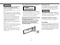
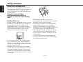
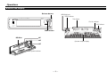
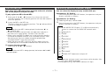
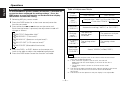
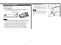
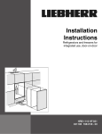
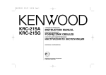
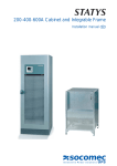
KMD-D401
3 DISC AND 1 DISC MD AUTO CHANGER
INSTRUCTION MANUAL
B64-1955-00 (EN)
English
Contents
Safety precautions
Before use
2WARNING
Safety Precautions ........................................................................2
To prevent injury or fire, take the
following precautions:
Operations
Buttons and Display ......................................................................5
MD Changer Play ..........................................................................6
Plus-one MD play ..........................................................................7
Switching Spectrum Analyzer Display...........................................7
Menu Systems..............................................................................8
Theft Deterrent Faceplate .............................................................9
• Insert the unit all the way in until it is fully
locked in place. Otherwise it may fall out of
place when jolted.
• To prevent a short circuit, never put or leave
any metallic objects (such as coins or metal
tools) inside the unit.
• If the unit starts to emit smoke or strange
smells, turn off the power immediately and
consult your Kenwood dealer.
• Make sure not to get your fingers caught
between the faceplate and the unit.
• Be careful not to drop the unit or subject it to
strong shock.
The unit may break or crack because it
contains glass parts.
Installation
Accessories.................................................................................10
Installation Procedure..................................................................10
Connections ................................................................................11
Installation ...................................................................................11
Troubleshooting guide .................................................13
Specifications ................................................................15
US and foreign patents licensed from
Dolby Laboratories.
—2—
2CAUTION
To prevent damage to the machine,
take the following precautions:
• Make sure to ground the unit to a negative
12V DC power supply.
• Do not open the top or bottom covers of the
unit.
• Do not install the unit in a spot exposed to
direct sunlight or excessive heat or humidity.
Also avoid places with too much dust or the
possibility of water splashing.
• Do not set the removed faceplate or the
faceplate case in areas exposed to direct
sunlight, excessive heat or humidity. Also
avoid places with too much dust or the
possibility of water splashing.
• To prevent deterioration, do not touch the
terminals of the unit or faceplate with your
fingers.
• Do not subject the faceplate to excessive
shock, as it is a piece of precision equipment.
• Do not place any object between the
faceplate and the unit.
• During installation, do not use any screws
except for the ones provided. The use of
improper screws might result in damage to
the main unit.
The marking of products using lasers
(Except for some areas)
CLASS 1
LASER PRODUCT
The label is attached to the chassis/case and
says that the component uses laser beams
that have been classified as Class 1. It means
that the unit is utilizing laser beams that are
of a weaker class. There is no danger of
hazardous radiation outside the unit.
Setting of the O-N switch will be required
depending on the centre unit that is to be
connected. (See page 10.)
The operations you perform and the
resultant operation of the unit will differ
depending on the setting of the O-N
switch. Please see the appropriate
description of operations for the "O" or
"N" switch setting.
2
3
1
O
N
O
—3—
N
Cleaning the Unit
If the faceplate of this unit is stained, wipe it
with a dry soft cloth such as a silicon cloth.
If the faceplate is stained badly, wipe the
stain off with a cloth moistened with neutral
cleaner, then wipe neutral detergent off.
2CAUTION
Applying spray cleaner directly to the unit
may affect its mechanical parts. Wiping the
faceplate with a hard cloth or using a volatile
liquid such as thinner or alcohol may scratch
the surface or erases characters.
Cleaning the Faceplate Terminals
If the terminals on the unit or faceplate get
dirty, wipe them with a dry, soft cloth.
Lens Fogging
Right after you turn on the car heater in cold
weather, dew or condensation may form on
the lens in the MD player of the unit. Called
lens fogging, MDs may be impossible to play.
In such a situation, remove the disc and wait
for the condensation to evaporate. If the unit
still does not operate normally after a while,
consult your Kenwood dealer.
English
Safety precautions
IMPORTANT INFORMATION
This unit is NOT designed to be connected
directly to control units that are manufactured
and sold before 1994. If used with such
units, an optional CA-SD200 (sold separately)
must be used.
FAILURE TO FOLLOW THESE
INSTRUCTIONS MAY RESULT IN
DAMAGE TO THIS UNIT AND CONTROL
UNIT.
Handling Mini discs
• The MD shutter is designed so that it cannot
be opened. If forced open, the cartridge will
be damaged and use of the MD will no
longer be possible. If the shutter has been
opened due to some cause, be careful not to
touch the recording portion with a finger.
Doing so will cause the sound to skip.
• Do not leave the MD in the unit for a
prolonged period. The ejected MD should be
placed in an MD case for storage.
• Do not leave the MD in a place exposed to
direct sunlight (such as on a instrument
panel) or in other places that reach high
temperatures. The MD cartridge will become
misshapen and will no longer be usable.
• MDs designed for use with data cannot be
used. Please use MDs designed for music.
• Do not use lens cleaners. Doing so will lead
to breakdown.
• If the MD performance time exceeds 100
minutes, the lower two digits are displayed
for the performance time.
• Do not use an MD that has a peeling label.
Use of an MD that has a loose or peeling
label may cause problems, such as the label
coming off inside the player and the resultant
inability to eject the MD.
• Wipe away dirt or dust from the cartridge
surface with a dry cloth before use. Using an
oil-soiled cartridge in particular may result in
the disc not loading or being unable to eject
it. (At time of cleaning, be careful not to open
the shutter.)
—4—
Operations
Buttons and Display
Release button
MENU indicator
DEMO indicator
3 MD CHANGER + 1 PLAYER
KMD-D401
24BIT ATRAC
OPERATION
Title display
MENU
DISP
Disc No. indicator
DISC indicator
DASC
DIGITAL AUDIO
MINI DISC
60
120
250
380
500
750
1k
2k
4k
8k
16k
11BAND
SPECTRUM ANALYZER
DISP button
01
02
MD Slot
2
1
Spectrum analyzer display
3
03
Opration indicator
—5—
English
Operations
MD Changer Play
To set MDs in the main unit:
1 Insert the first MD in the MD slot.
The first MD is set in the play position.
2 Insert the second MD in the MD slot.
The second MD is held in the disc No.2 stack position.
3 Insert the third MD in the MD slot.
The third MD is held in the disc No.3 stack position.
NOTE
• The 0 buttons change colour according to the operation
state, as follows.
If a disc is present in the stack position:
The 0 button corresponding to the disc number glows red.
If no disc is present in the stack position:
The 0 button corresponding to the disc number glows green.
• An MD cannot be inserted while the operation indicator is
red. Wait until it changes to green, then insert the MD.
• When an MD is inserted, it will be stored as the smallest
available disc number. For example, if disc No.1 and disc
No.2 are both empty, the inserted disc will be denoted as
disc No.1.
To play an MD:
Select the disc changer mode on the centre unit.
NOTE
Disc No.3 being played: the
indicator blinks
To store an MD:
Press one of the 01 - 03 buttons for at least one second.
The MD currently set in the play position will be stored in the
stacker position.
NOTE
When an MD has been stored in the stack position, the unit will
enter one of the states listed below, depending on the type of
centre unit connected.
Centre units brought on to the market in 1998 or earlier:
The system will remain in the disc play STOP state.
Centre units brought on sale in 1999 or later (certain models
excluded):
The system will switch to the tuner mode.
To eject an MD:
Press one of the 01 - 03 buttons depending on the disc you
want to remove.
NOTE
The 0 button with the disc number corresponding to the MD
currently being ejected will blink green.
NOTE
When the O-N switch is set to "O", the phrase "NO NAME" will be
displayed if the centre unit display is switched accordingly, but
the DNPS (Disc Name Pre-Set) function cannot be used on the
MD in the main unit.
• If your system is connected to a centre unit brought on to
the market in 1999 or later (excluding certain models), it will
automatically switch to MD play mode when the first MD is
inserted, even if there are other sources.
• The 0 button with the disc number corresponding to the MD
currently playing will blink red.
To switch the MD:
Select the disc number using the DISC+ or DISC- button on
the centre unit.
Disc No.1 being played: the
indicator blinks
Disc No.2 being played: the
indicator blinks
—6—
Plus-one MD play
Switching Spectrum Analyzer Display
Even when three MDs have been set in the main unit, a further
MD can be played as the plus-one MD.
To play a plus-one MD (a fourth MD):
1 Press one of the 01 - 03 buttons for at least one second.
The MD currently set in the play position will now be stored in
the stack position.
2 Insert the MD in the MD slot.
The disc is then set in the play position. The
and the disc begins to play.
indicator blinks
You can select the display to enjoy sounds with eyes.
Operation for "N" Setting:
Each time you press the DISP button, the spectrum analyzer
display switches as follows;
Operation for "O" Setting:
1 Selecting MD play source mode.
2 Each time you press the DISP button, the spectrum analyzer
display switches as follows;
▼
NOTE
1 "SCAN MODE ON":Displays 2 to 0 are automatically
shown in succession for about five seconds each.
• While the plus-one MD is being played, the buttons 01 to
03 will blink red.
• An MD cannot be inserted when the operation indicator is
red. Wait until it goes green, and then insert the MD.
• When a plus-one MD has been set in the main unit, the disc
cannot be changed or the disc scan switched ON/OFF from
the centre unit, nor can random magazine playback be
switched ON/OFF from the centre unit.
• While the plus-one MD is playing, the disc repeat function
will operate, but it cannot be cancelled from the centre unit.
To remove the plus-one MD:
Press one of the 01 - 03 buttons.
▼
2 "PEAK HOLD"
▼
3 "LASER"
▼
4 "H-SCOPE"
▼
5 "FIREWORKS"
▼
6 "SQUASH"
▼
7 "V-SCOPE"
▼
8 "BLIZZERD"
▼
NOTE
9 "KISS"
While the plus-one MD is being ejected, the buttons 01 to 03
will blink green.
▼
0 "SIDE WAVE"
▼
! "SPEANA OFF":Spectrum analyzer off.
NOTE
• The spectrum analyzer name is not shown while the disc title
or track title is being displayed.
• During operation 1, the DEMO indicator will light.
—7—
English
Operations
Menu System
Table of Adjustment Mode
To accommodate a greater number of functions, a function set
system has been employed for making settings. Press the
DISP button to enter the function set mode and then display
the function to make the setting.
Adjustment
mode
(Display)
1 Selecting MD play source mode.
2 Press the DISP button for at least one second, enter the
Operation of Control button
DISC+ button
DISC- button
Selectable
title*1
(“TITLE”)
↔ Analyzer title (“ANA”) ↔ Disc title(“DISC”)↔
↔ Track title (“TRACK”) ↔
Title scroll*2
(“SCROLL”)
Automatic scrolling (“AUTO”) ↔ Off (“OFF”)
function set mode.
3 Press either the 4 or ¢ button on the centre unit.
Each time the button is pressed, the adjustment mode will
change as follows:
Spectrum
Analyzer
level*3
(“ANA LV”)
∞
”MENU TITLE" (Selectable title)*1
∞5
”MENU SCROLL" (Title scroll)*2
∞5
”MENU ANA LV" (Spectrum analyzer level)*3
∞5
”MENU LCD CNT" (LCD contrast level)*4
∞5
”MENU COLOR" (Selectable Illumination)
LCD contrast
level*4
(“LCD CNT”)
The spectrum
analyzer level
increased.
The spectrum analyzer
level decreased.
The setting values
higher.
The setting values
lower.
5
Selectable
Illumination
(“COLOR”)
4 Press the DISC+ or DISC- button on the centre unit.
Look at the table to adjust the mode being displayed.
Green(“GREEN”)↔Red(“RED”)
5 Press the DISP button to end the function set mode.
NOTE
*1: The spectrum analyzer name is not shown while the disc title or
track title are being displayed.
*2: • Even when the system is set to "OFF", the title will
appear once on the scroll display if the track or the disc is
switched.
• The analyzer name is shown at all times on the scroll
display.
*3: The volume changes according to the volume setting on the centre
unit, so set the centre unit to a normal volume level before
adjusting it.
*4: The contrast on the spectrum analyzer display is not adjustable.
—8—
Theft Deterrent Faceplate
The faceplate of the unit can be detached and taken with you,
helping to deter theft.
Removing Faceplate:
Press the release button and drop open the faceplate.
In its dropped condition, whilst drawing the faceplate to one
side, pull it to the front and remove it.
Release button
2
3
1
3 MD CHANGER + 1 PLAYER
KMD-D401
24BIT ATRAC
OPERATION
DISP
Reattaching Faceplate:
Hold the faceplate so that the
operation face faces the front
toward you and press until it
locks. The faceplate will be set
and the unit will be operational.
DASC
DIGITAL AUDIO
MINI DISC
60
120
250
380
500
750
1k
2k
4k
8k
16k
£
NOTE
When there is difficulty in setting
the faceplate, align the depression
on the left side of the faceplate
with the shaft of the unit, then
lock.
Shaft
Depression
11BAND
SPECTRUM ANALYZER
NOTE
• If the controls remain untouched for a period of 5 minutes or
more after the panel has dropped open or been removed, the
disc will automatically stop playing. (A warning beep starts
sounding 30 seconds before play stops automatically.)
• The faceplate is a precision piece of equipment and can be
damaged by shocks or jolts. For that reason, keep the
faceplate in its special storage case whilst detached.
• Do not expose the faceplate or its storage case to direct
sunlight or excessive heat or humidity. Also avoid places
with too much dust or the possibility of water splashing.
—9—
Accessories
Installation Procedure
English
External view
......... Number of items
1
.........2
2
.........2
3
.........1
2CAUTION
The use of any accessories except for those provided might result
in damage to the unit. Make sure only to use the accessories
shipped with the unit, as shown above.
The O-N switch should be set according to the control unit in
use as well as to the connected models.
When the centre unit is compatible with the "N"-operation, set
the O-N switch to "N". When it is not compatible with the "N"operation, set the O-N switch to "O" because the operation is
not available. The initial setting of the switch is "N".(see page 3)
1. To prevent a short circuit, remove the key from the ignition and
disconnect the - battery.
2. Set the O-N switch of this unit to suit the centre unit.
3. Connect the speaker input wires to the front speaker wires of the
wiring hernees of the centre unit.
4. Connect the control cable to the control connector.
5. Install the unit in your car.
6. Reconnect the - battery.
7. Press the reset button on the centre unit.
2CAUTION
• Do not connect the changer control cable while the centre unit
is turned on.
• Be sure to press the reset button after installation.
• Whether the centre unit in use is compatible with the "N"operation or not can be identified by referring to its instruction
manual (description of the disc control mode, etc.).
• If you use the changer switching unit, see the instruction
manual for the KCA-S210A included in the unit. Set the O-N
switch on the KCA-S200 to "O".
• Do not let unconnected wires or terminals touch metal on the
car or anything else conducting electricity. To prevent a short
circuit, do not remove the caps on the ends of the unconnected
wires or the terminals.
• After the unit is installed, check whether the brake lamps,
blinkers, wipers, etc. on the car are working properly.
• Mount the unit so that the mounting angle is 30° or less.
— 10 —
Connections
Installation
■ Installation
Control input
Firewall or metal support
White
White/Black
Centre unit
Screw (M4X8)
(commercially
available)
White/Black
–
+
FRONT • L
White
Gray/Black
–
Gray
Metal mounting strap
(commercially available)
On cars where there is no compartment in the centre for
installing a car audio unit:
Use the spacer 2 to affix the centre unit sleeve and the sleeve
attached to the main unit in such a way that they are correctly
aligned both depthwise and horizontally.
On cars lacking a centre
compartment
R
Speaker input cable(Accessory3)
U
P
Gray/Black
Gray
KMD-D401
Self-tapping
screw
(commercially
available)
+
FRONT • R
Bend the tabs of the
mounting sleeve with
a screwdriver or
similar utensil and
attach it in place.
2
L
2CAUTION
If the speaker input cable is not connected, or connected wrongly,
the spectrum analyzer will not be displayed.
— 11 —
Installation
■ Removing the Unit
English
■ Removing the hard rubber frame
1 Engage the catch pins on the removal tool and remove the two
1 Refer to the section “Removing the hard rubber frame” and
locks on the lower level.
Lower the frame and pull it forward as shown in the figure.
2 Remove the Hex-head screw with integral washer (M4´8) on
then remove the hard rubber frame.
the back panel.
Catch
3 Insert the two removal tools deeply into the slots on each side,
as shown.
Lock
Screw (M4X8)
(commercially
available)
Accessory1
Removal tool
Catch facing up
2 When the lower level is removed, remove the upper two
locations.
4 Lower the removal tool
toward the bottom, and pull
out the unit halfway whilst
pressing towards the
inside.
2CAUTION
Be careful to avoid injury from the catch pins on the removal tool.
NOTE
The frame can be removed from the top side in the same
manner.
5 Pull the unit all the way out
with your hands, being
careful not to drop it.
— 12 —
Troubleshooting Guide
What might seem to be a malfunction in your unit may just be the result of slight misoperation or miswiring. Before
calling service, first check the following table for possible problems.
PROBLEM
POSSIBLE CAUSE
SOLUTION
The disc control mode cannot
be selected.
No cable has been connected to the disc changer input
terminal on the unit.
Connect the control cable to the disc changer input terminal
on the centre unit.
The disc cannot be changed.
Four MDs have been set in the main unit.
Remove the MD currently playing.
No sound can be heard, or the
volume is low.
The spectrum analyzer is not
displayed.
Attenuator is turned on.
Turn off Attenuator.
The fader or balance settings are set all the way to one
side.
Reset the fader or balance settings.
5 minutes have elapsed since the panel dropped open.
When 5 minutes have elapsed since the panel dropped
open, the disc will automatically stop playing.
The speaker input cable is not connected.
Refer to the "Connections" section, and connect the cable.
The fader setting has been adjusted to the rear side.
Adjust the fader control on the centre unit to the centre
position.
The analyzer display level has been set too low.
Adjust it to a higher level.
The volume is too low.
Raise the volume, or alternatively, adjust the analyzer display
level to a higher level.
Nothing happens when the
buttons are pressed.
The computer chip in the unit is not functioning normally.
Press the reset button on the centre unit.
The MD cannot be inserted.
There is already an MD loaded.
Eject the currently loaded MD and then load the new one.
The MD does not load.
The insertion orientation of the MD is incorrect or the MD
is upside down.
Insert the MD in the proper orientation.
The MD loads but soon comes
out again.
Nothing is recorded on the MD.
Switch the MD for one that is recorded.
A track will not play.
Random play has been selected.
Turn off random play.
The system will not enter the
Menu mode.
The system is not in MD play mode.
If the main unit is not in MD play mode, it will not go into the
Menu mode.
— 13 —
Troubleshooting Guide
English
The following messages are displayed on the centre unit when certain problems are occurring in your system. Take
the recommended actions.
E-01 / EJECT No MD is loaded.
E-04
• The MD is extremely soiled.
• The MD has so many scratches.
NO PANEL
E-30
The faceplate of this unit has been removed.
] Replace it.
BLANK
Nothing has been recorded on the MD.
] The next MD will automatically be played.
NO TRACK
No tracks are recorded on the MD, although it has a title.
] The next MD will automatically be played.
E-99
Mecha Error
The unit is malfunctioning for some reason.
] Press the reset button on the centre unit. If the "E- 99" / "Mecha Error" code does not disappear, consult your nearest service
centre.
E-0d
HOLD
The protective circuit in the unit activates when the temperature inside the MD player exceeds 60°C (140°F), stopping all operation.
] Cool down the unit by opening the windows or turning on the air conditioner. As the temperature falls below 60°C (140°F), the
disc will start playing again.
— 14 —
Specifications
Specifications subject to change without notice.
MD player section
General
Laser diode ....................................................GaAlAs (l=780 nm)
Digital filter (D/A)......................................8 Times Over Sampling
D/A Converter......................................................................20 Bit
Frequency response (±1 dB) ...................................5 Hz – 20 kHz
Total harmonic distortion (1 kHz) .......................................0.03 %
Signal to Noise ratio.................................................90 dB (1 kHz)
Dynamic range ....................................................................87 dB
Channel separation ..............................................................80 dB
Spindle speed ...............................................400 – 900 rpm (CLV)
Wow & Flutter ........................................Below Measurable Limit
— 15 —
Operating voltage ..............................14.4 V (11 – 16 V allowable)
Current consumption ............................................................0.8 A
Installation size (W ´ H ´ D) ..........................180 ´ 50 ´ 160 mm
7-1/16 ´ 1-15/16 ´ 6-1/16 in.
Weight..................................................................1.3 kg (2.9 Lbs)