1
Owner’s Manual
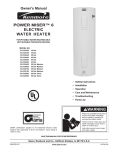
THE ECONOMIZER™ 6
COMPACT ELECTRIC
WATER HEATER
FOR POTABLE WATER HEATING ONLY.
NOT SUITABLE FOR SPACE HEATING.
MODEL NO.
153.316040
153.316050
153.316060
153.316070
153.316331
153.326060
153.326070
153.326331
6 GALLON
10 GALLON
19 GALLON SHORT
19.9 GALLON TALL
30 GALLON
19 GALLON 240 V. SHORT
19.9 GALLON 240 V. TALL
30 GALLON 240 V.
• Safety Instructions
• Installation
• Operation
• Care and Maintenance
• Troubleshooting
• Parts List
GAMA certification applies to all residential electric water heaters
with capacities of 20 to 120 Gallons. Input rating of 12kW or
less.
SAVE THIS MANUAL FOR FUTURE REFERENCE.
Sears, Roebuck and Co., Hoffman Estates, IL 60179 U.S.A
PRINTED 0607
www.sears.com
PART NO. 185775-000
SAFE INSTALLATION, USE AND SERVICE
Your safety and the safety of others is extremely important in the installation, use and servicing of this water heater.
Many safety-related messages and instructions have been provided in this manual and on your own water heater to warn
you and others of a potential injury hazard. Read and obey all safety messages and instructions throughout this manual.
It is very important that the meaning of each safety message is understood by you and others who install, use or service
this water heater.
This is the safety alert symbol. It is used to alert you
to potential personal injury hazards. Obey all safety
messages that follow this symbol to avoid possible
injury or death.
DANGER
DANGER indicates an imminently hazardous
situation which, if not avoided, could result
in death or injury.
WARNING
WA R N I N G i n d i c a t e s a p o t e n t i a l l y
hazardous situation which, if not avoided,
could result in death or injury.
CAUTION
CAUTION
CAUTION indicates a potentially hazardous
situation which, if not avoided, may result
in minor or moderate injury.
CAUTION used without the safety alert
symbol indicates a potentially hazardous
situation which, if not avoided, could
result in property damage.
All safety messages will generally tell you about the type of hazard, what can happen if you do not follow the safety message
and how to avoid the risk of injury.
The California Safe Drinking Water and Toxic Enforcement Act requires the Governor of California to publish a list of substances
known to the State of California to cause cancer, birth defects, or other reproductive harm, and requires businesses to warn
of potential exposure to such substances.
This product contains a chemical known to the State of California to cause cancer, birth defects, or other reproductive harm.
This appliance can cause low level exposure to some of the substances listed, including formaldehyde.
IMPORTANT DEFINITIONS
• Sears Service Center: The Sears Service Center has the ability equivalent to a licensed tradesman in the fields of plumbing and
electrical work including a thorough understanding of the requirements of the National Electrical Code as it relates to the installation
of electric water heaters. The Sears Service Center also has a thorough understanding of this instruction manual, and is able to
perform repairs strictly in accordance with the service guidelines provided by the manufacturer.
GENERAL SAFETY
TABLE OF CONTENTS
SAFE INSTALLATION, USE AND SERVICE........................... 2
Temperature Settings....................................................... 13
GENERAL SAFETY................................................................. 3
Thermostat Adjustment.................................................... 13
Table of Contents............................................................ 4
Temperature-Pressure Relief Valve Operation................ 13
INTRODUCTION...................................................................... 5
Draining...................................................................... 13,14
Product Specifications................................................. 5
Thermostat Removal/Replacement................................. 14
MATERIALS AND BASIC TOOLS NEEDED............................ 6
Element Cleaning/Replacement.................................14-16
Materials Needed............................................................... 6
Drain Valve Washer Replacement................................... 17
Basic Tools......................................................................... 6
Anode Rod Inspection..................................................... 17
Additional Tools Needed When Sweat Soldering.............. 6
Service............................................................................. 17
Troubleshooting Guide..........................................18-20
Installation Instructions.......................................7-12
Start Up Conditions........................................................ 18
Removing the Old Water Heater..................................... 7,8
Facts to Consider About the Location................................ 8
Thermal Expansion....................................................... 18
Insulation Blankets............................................................. 8
Strange Sounds............................................................ 18
Water Piping................................................................. 9,10
Operational Conditions...............................................18-20
T & P Valve and Pipe Insulation....................................... 10
Smelly Water............................................................ 18,19
Temperature-Pressure Relief Valve............................ 10,11
“Air” in Hot Water Faucets............................................ 19
Filling the Water Heater................................................... 11
Rumbling Noise............................................................. 19
Wiring ........................................................................ 11,12
High Temperature Shut Off System............................... 19
Wiring Diagrams.............................................................. 11
Not Enough or No Hot Water......................................... 20
Wiring Connections.......................................................... 12
Water Is Too Hot............................................................ 20
Service and ADJUSTMENT.........................................12-17
Leakage Checkpoints...................................................... 21
Temperature Regulation.................................................. 12
REPAIR PARTS LIST........................................................ 22,23
Thermostat....................................................................... 12
Warranty........................................................................... 24
INTRODUCTION
Thank You for purchasing a Sears water heater. Properly
installed and maintained, it should give you years of trouble
free service. It is strongly suggested that this new water heater
be professionally installed, contact the local Sears Service
Center or any Sears store. They will arrange for prompt,
quality installation by Sears authorized contractors.
safety rules, the water heater will not operate properly. It
could cause DEATH, SERIOUS BODILY INJURY, AND/OR
PROPERTY DAMAGE.
Abbreviations Found In This Instruction Manual:
•
•
•
•
•
•
ANSI - American National Standards Institute
ASME - American Society of Mechanical Engineers
GAMA - Gas Appliance Manufacturers Association
NEC - National Electrical Code
NFPA - National Fire Protection Association
UL - Underwriters Laboratories Inc.
This manual contains instructions for the installation, operation,
and maintenance of the electric water heater. It also contains
warnings throughout the manual that you must read and
understand. All warnings and all instructions are essential
to the proper operation of the water heater and your safety.
READ THE ENTIRE MANUAL BEFORE ATTEMPTING TO
INSTALL OR OPERATE THE WATER HEATER.
2. The installation must conform with these instructions
and the local code authority having jurisdiction and the
requirements of the power company. In the absence of
local code requirements follow NFPA-70, the National
Electrical Code (current edition), which may be ordered
from: National Fire Protection Association, 1 Batterymarch
Park, Quincy, MA 02269.
Preparing for the Installation
3. If after reading this manual you have any questions or do not
understand any portion of the instructions, call Sears Service Center.
1. Read the “General Safety” section of this manual first and
then the entire manual carefully. If you don’t follow the
4. Carefully plan your intended placement of the water
heater. INSTALLATION OR SERVICE OF THIS WATER
HEATER REQUIRES ABILITY EQUIVALENT TO THAT OF
A LICENSED TRADESMAN IN THE FIELD INVOLVED.
PLUMBING AND ELECTRICAL WORK ARE REQUIRED.
an earthquake. See instructions for correct installation
procedures. Instructions may be obtained from California
Office of the State Architect, 400 P Street, Sacramento,
CA 95814.
Examine the location to ensure the water heater complies with the
“Facts to Consider About the Location” section in this manual.
6. Massachusetts Code requires this water heater to be
installed in accordance with Massachusetts 248-CMR
2.00: State Plumbing Code and 248-CMR 5.00.
5. For California installation this water heater must be braced,
anchored, or strapped to avoid falling or moving during
PRODUCT SPECIFICATIONS
MAXIMUM FUSE
TANK
DIMENSIONS
ELEMENT
MINIMUM
OR CIRCUIT
CAPACITY
IN INCHES (mm)
RECOVERY RATE
WATTAGE
MODEL
IN GALLONS
GALS.PER HOUR
WIRE SIZE*
BREAKER
NUMBER
(LITERS)
DIA.
HEIGHT
@900F Rise
120 Volt 240 Volt
(GAUGE)
SIZE (AMPS)
153.316040
6 (22.7)
14.250” (362) 15.375” (391)
7.5
1650
----
12
20
153.316050
10 (37.8)
16” (406) 18.25” (464)
7.5
1650
----
12
20
153.316060
19 (71.9)
18” (457) 24.9” (632)
7.5
1650
----
12
20
153.316070
19.9 (75.3)
16” (406) 31.62” (803)
7.5
1650
----
12
20
153.316331
30 (113.6)
22” (559)
30” (762)
7.5
1650
----
12
20
153.326060
19 (71.9)
18” (457) 24.9” (632)
9.1
----
2000
14
15
153.326070
19.9 (75.3)
16” (406) 31.62” (803)
9.1
----
2000
14
15
153.326331
30 (113.6)
22” (559)
30” (762)
9.1
----
2000
14
15
* Wiring size based on standard 60°C copper wire. If distance from fuse box to water heater is more than 90 feet, refer to your local electrical code.
Some compact models have labeled optional plumbing connections see below.
MODEL
NUMBER
STANDARD
SIDE COLD INLET
STANDARD
SIDE HOT INLET
STANDARD
SIDE T&P
MODEL HAS OPTIONAL
TOP COLD INLET
MODEL HAS OPTIONAL
TOP HOT OUTLET OR T&P
153.316040
YES
YES
YES
YES, PLUGGED
YES, PLUGGED
153.316050
YES
YES
YES
NO
YES, PLUGGED
153.316060
YES
YES
YES
YES, PLUGGED
YES, PLUGGED
153.316070
YES
YES
YES
YES, PLUGGED
YES, PLUGGED
153.316331
YES
YES
YES
NO
NO
153.326060
YES
YES
YES
YES, PLUGGED
YES, PLUGGED
153.326070
YES
YES
YES
YES, PLUGGED
YES, PLUGGED
153.326331
YES
YES
YES
NO
NO
MATERIALS AND BASIC TOOLS NEEDED
Materials Needed
To simplify the installation Sears has available the installation parts shown below. You may or may not need all of these materials,
depending on your type of installation.
WATER HEATER INSTALLATION KIT WITH
FLEXIBLE CONNECTORS FOR 3/4” OR 1/2”
THREADED OR COPPER PLUMBING.
E X PA N S I O N TA N K S F O R T H E R M A L
EXPANSION CONDITIONS AVAILABLE IN
2 GALLONS , AND 5 GALLONS capacity
through local Sears store or
Service Center.
Basic Tools
DRAIN PANS AVAILABLE IN 20”
DIAMETER FOR WATER HEATERS
HAVING A DIAMETER 18” OR
LESS, 24” DIAMETER FOR WATER
HEATERS HAVING A DIAMETER
22” OR LESS AND AVAILABLE
IN 28” DIAMETER FOR WATER
HEATERS HAVING A DIAMETER
26” OR LESS.
Additional Tools Needed When Sweat
Soldering
You may or may not need all of these tools, depending on your
type of installation. These tools can be purchased at your local
Sears store.
Tubing Cutters or Hacksaw
Propane Torch
Soft Solder
Solder Flux
Emery Cloth
Wire Brushes
Pipe Wrench (2)
Screwdriver
6 Foot Tape or Folding Rule
Garden Hose
Drill
Pipe Dope or Teflon Tape
TUBING CUTTER
DRILL
HACKSAW
SLOT-HEAD SCREWDRIVER
ROLL OF TEFLON TAPE (USE ON
WATER CONNECTIONS)
PHILLIPS SCREWDRIVER
ROLL OF
EMERY CLOTH
PIPE DOPE (SQUEEZE TUBE)
USE FOR WATER CONNECTIONS
ROLL OF
LEAD-FREE
SOFT SOLDER
3/4” (19 mm) WIRE BRUSH
GARDEN HOSE
6 FOOT TAPE
PROPANE
TORCH
PIPE WRENCH
1/2” (13 mm) WIRE BRUSH
SOLDER
FLUX
INSTALLATION INSTRUCTIONS
Removing the Old Water Heater
The water passing out of the drain valve may be extremely hot.
To avoid being scalded, make sure all connections are tight and
that the water flow is directed away from any person.
4. Check again to make sure the electrical supply is turned “OFF”
to the water heater. Then disconnect the electrical supply
connection from the water heater junction box.
FIGURE 1.
1. Turn “OFF” electrical supply to the water heater.
FIGURE 5.
5. a. FIGURE 2.
2. Turn “OFF” the water supply to the water heater at the water
shut-off valve or water meter.
If you have copper piping to the water heater, the two
copper water pipes can be cut with a hacksaw
approximately four inches away from where they connect
to the water heater. This will avoid cutting off the pipes
too short. Additional cuts can be made later if necessary.
Disconnect the temperature-pressure relief valve
drain line. When the water heater is drained, disconnect
the hose from the drain valve. Close the drain valve.
The water heater is now completely disconnected and
ready to be removed.
FIGURE 3.
3. Attach a hose to the water heater drain valve and put the
other end in a floor drain or outdoors. Open the water heater
drain valve. Open a nearby hot water faucet which will relieve
pressure in the water heater and speed draining.
FIGURE 6.
FIGURE 4.
b. If you have galvanized pipe to the water heater,
loosen the two galvanized pipes with a pipe wrench at the
union in each line. Also disconnect the piping
remaining to the water heater. These pieces should
be saved since they may be needed when
reconnecting the new water heater. Disconnect the
temperature-pressure relief valve drain line. When the
water heater is drained, disconnect the hose from the
drain valve. Close the drain valve. The water heater is
now completely disconnected and ready to be
removed.
Water heater life depends upon water quality, water pressure
and the environment in which the water heater is installed. Water
heaters are sometimes installed in locations where leakage may
result in property damage, even with the use of a drain pan piped
to a drain. However, unanticipated damage can be reduced or
prevented by a leak detector or water shut-off device used in
conjunction with a piped drain pan. These devices are available
from some plumbing wholesalers and retailers, and detect and
react to leakage in various ways:
FIGURE 7.
• Sensors mounted in the drain pan that trigger an alarm or turn
off the incoming water to the water heater when leakage is
detected.
• Sensors mounted in the drain pan that turn off the water supply
to the entire home when water is detected in the drain pan.
• Water supply shut-off devices that activate based on the water
pressure differential between the cold water and hot water pipes
connected to the water heater.
Mineral buildup or sediment may have accumulated in the
old water heater. This causes the water heater to be much
heavier than normal and this residue, if spilled out, could cause
staining.
Facts to Consider About the Location
You should carefully choose an indoor location for the new water
heater, because the placement is a very important consideration
for the safety of the occupants in the building and for the most
economical use of the appliance. This water heater is not
intended for outdoor installation.
INSTALLATION IN RESIDENTIAL GARAGES: The water heater
must be located and/or protected so it is not subject to physical
damage by a moving vehicle.
Whether replacing an old water heater or putting the water
heater in a new location, the following critical points must be
observed.
• The location selection must provide adequate clearances for
servicing and proper operation of the water heater.
Insulation Blankets
• The location selected should be indoors as close to and as
centralized with the water piping system as possible. This
water heater, as well as all water heaters, will eventually leak.
Do not install without adequate drainage provisions so water
flow will not cause damage.
Insulation blankets are available to the general public for external
use on electric water heaters but are not necessary with this
product. The purpose of an insulation blanket is to reduce
the standby heat loss encountered with storage tank heaters.
Your water heater meets or exceeds the National Appliance
Energy Conversation Act standards with respect to insulation
and standby loss requirements, making an insulation blanket
unnecessary.
Should you choose to apply an insulation blanket to this heater,
you should follow these instructions below. Failure to follow
these instructions can result in fire, serious personal injury,
or death.
• Do not cover the temperature and pressure relief (T & P) valve
with an insulation blanket.
WATER HEATERS EVENTUALLY LEAK: Installation of the water
heater must be accomplished in such a manner that if the tank
or any connections should leak, the flow of water will not cause
damage to the structure. When such locations cannot be avoided,
a suitable drain pan should be installed under the water heater.
Drain pans are available at your local Sears stores. Such drain
pans must be piped to an adequate drain.
• Do not cover the instruction manual. Keep it on the side of
the water heater or nearby for future reference.
• Do obtain new warning and instruction labels for placement
on the blanket directly over the existing labels.
Water Piping
meter with a check valve, etc... in the cold water supply;
means must be provided to control thermal expansion.
Contact the local utility or Sears Service Center on how to
control this situation.
NOTE: If using copper tubing, solder tubing to an adapter
before attaching the adapter to the water connections. Do
not solder the water supply lines directly to the connections.
It will harm the fittings on the water heater.
HOTTER WATER CAN SCALD: Water heaters are intended
to produce hot water. Water heated to a temperature which
will satisfy clothes washing, dish washing, and other sanitizing
needs can scald and permanently injure you upon contact.
Some people are more likely to be permanently injured by
hot water than others. These include the elderly, children, the
infirm, or physically/mentally handicapped. If anyone using hot
water in your home fits into one of these groups or if there is a
local code or state law requiring a certain temperature water
at the hot water tap, then you must take special precautions.
In addition to using the lowest possible temperature setting
that satisfies your hot water needs, a means such as a mixing
valve, shall be used at the hot water taps used by these
people or at the water heater. Mixing valves are available at
plumbing supply or hardware stores. Follow manufacturers
instructions for installation of the valves. Before changing
the factory setting on the thermostat, read the “Temperature
Regulation” section in this manual.
NOTE: To protect against untimely corrosion of hot and cold
water fittings, it is strongly recommended that di electric
unions or couplings be installed on this water heater when
connected to copper pipe.
1. Look at the side of the water heater. The hot water outlet is
marked hot. Put two or three turns of teflon tape around the
threaded end of the threaded-to-sweat coupling and around
the 3/4” threaded nipple. Using flexible connectors, connect
the hot water pipe to the hot water outlet of the water heater.
2. Look at the side of the water heater. The cold water inlet is
marked cold. Put two or three turns of teflon tape around the
threaded end of the threaded-to-sweat coupling and around
the 3/4” threaded nipple. Using flexible connectors, connect the
cold water pipe to the cold water inlet of the water heater.
See Figure 8 for mixing valve usage.
FIGURE 8.
Figure 9 shows the attachment of the water piping to the
water heater. The water heater is equipped with 3/4” water
connections.
FIGURE 9.
NOTE: Your water heater is insulated to minimize heat
loss from the tank. Further reduction in heat loss can be
accomplished by insulating the hot water lines from the
water heater.
If a water heater is installed in a closed water supply system;
such as one having a back-flow preventer, check valve, water
Optional Installation Instructions
FIGURE 9A.
NOTE: Figure above is used to illustrate installation of
T&P and pipe insulation only. As indicated in PRODUCT
SPECIFICATION Section. Actual optional Cold & Hot / T&P
spud location vary from model to model.
Some compact models have optional plumbing
connections. On these units, if top connection is
preferred over the side connection, use the following
instructions as they apply to your connection:
Temperature-Pressure Relief Valve
To c h a n g e Te m p e r a t u r e a n d P r e s s u r e ( T & P ) v a l v e
locatio n: R emo ve 3/4” pl ug fro m op en in g i n jacket
top. Replace 3/4” plug opening with T&P valve;
plug original T&P valve opening with 3/4” plug. be
sure to reapply pipe j oint compound or
teflon tape around the threaded ends
of the temperature and pressure ( T & P )
valve and the 3/4” plug when reinstalling
components.
To change Cold Inlet location: Remove 3/4” plug from
opening in jacket top. Replace 3/4” plug opening with
Cold Inlet nipple; plug original Cold Inlet opening with 3/4”
plug. be sure to reapply pipe joint compound
or teflon tape around the threaded ends
of the cold inlet nipple and the 3/4” plug
when reinstalling components.
This heater is provided with a properly certified combination
temperature - pressure relief valve by the manufacturer.
To change Hot Outlet location: Screw 3/4” NPT galvanized
cap (not included, purchase locally) onto Side Hot Outlet
and install 3/4” NPT nipple (not included, purchase
locally) in the opening identified as HOT/T&P location.
be sure to reapply pipe j oint compound
or teflon tape around the threaded ends
of the 3/4” npt nipples when reinstalling
components.
The valve is certified by a nationally recognized testing laboratory
that maintains periodic inspection of production of listed equipment
of materials as meeting the requirements for Relief for Hot
Water Supply Systems, ANSI Z21.22 • CSA 4.4, and the code
requirements of ASME.
If replaced, the valve must meet the requirements of local codes,
but not less than a combination temperature and pressure relief
valve certified as indicated in the above paragraph.
T & P Valve and Pipe Insulation
The valve must be marked with a maximum set pressure not to
exceed the marked hydrostatic working pressure of the water
heater (150 psi = 1,035 kPa) and a discharge capacity not less
than the water heater input rate as shown on the model rating
plate. (Electric heaters - watts x 3.412 equal Btu/hr input rate)
Remove insulation for T & P valve and pipe connections from
carton.
Fit pipe insulation over the incoming cold water line and the
hot water line. Make sure that the insulation is against the side
jacket of the heater.
Your local jurisdictional authority, while mandating the use
of a temperature-pressure relief valve complying with
ANSI Z21.22 • CSA 4.4, may require a valve model different
from the one furnished with the water heater.
Fit T & P valve insulation over valve. Make sure that the insulation
does not interfere with the lever of the T & P valve.
Compliance with such local requirements must be satisfied
by the installer or end user of the water heater with a locally
Secure all insulation using tape.
10
prescribed temperature-pressure relief valve installed in the
designated opening in the water heater in place of the factory
furnished valve.
The temperature-pressure relief valve must be manually
operated at least once a year. Caution should be taken to
ensure that (1) no one is in front of or around the outlet of the
temperature-pressure relief valve discharge line, and (2) the
water manually discharged will not cause any bodily injury or
property damage because the water may be extremely hot.
For safe operation of the water heater, the relief valve must not
be removed from its designated opening nor plugged.
The temperature-pressure relief valve must be installed directly
into the fitting of the water heater designed for the relief valve.
Position the valve downward and provide tubing so that any
discharge will exit only within 6 inches (153 mm) above, or at any
distance below the structural floor. Be certain that no contact is
made with any live electrical part. The discharge opening must
not be blocked or reduced in size under any circumstances.
Excessive length, over 30 feet (9.14 m), or use of more than
four elbows can cause restriction and reduce the discharge
capacity of the valve.
If after manually operating the valve, it fails to completely
reset and continues to release water, immediately close
the cold water inlet to the water heater, follow the draining
instructions, and replace the temperature-pressure relief
valve with a new one.
No valve or other obstruction is to be placed between the
relief valve and the tank. Do not connect tubing directly to
discharge drain unless a 6 inch air gap is provided. To prevent
bodily injury, hazard to life, or property damage, the relief
valve must be allowed to discharge water in quantities should
circumstances demand. If the discharge pipe is not connected
to a drain or other suitable means, the water flow may cause
property damage.
FIGURE 10.
Filling the Water Heater
The Discharge Pipe:
• Shall not be smaller in size than the outlet pipe size of the
valve, or have any reducing couplings or other restrictions.
• Shall not be plugged or blocked.
• Shall be of material listed for hot water distribution.
• Shall be installed so as to allow complete drainage of both the
temperature-pressure relief valve, and the discharge pipe.
• Shall terminate at an adequate drain.
Never use this water heater unless it is completely full of water.
To prevent damage to the tank and heating element, the tank
must be filled with water. Water must flow from the hot water
faucet before turning “ON” power.
• Shall not have any shut-off valve between the relief valve and
tank nor in the discharge pipe.
To fill the water heater with water:
• Close the water heater drain valve by turning the handle to
the right (clockwise). The drain valve is located on the lower
front of the water heater.
• Open the cold water supply valve to the water heater.
NOTE: The cold water supply valve must be left open
when the water heater is in use.
• To insure complete filling of the tank, allow air to exit by
opening the nearest hot water faucet. Allow water to run until
a constant flow is obtained. This will let air out of the water
heater and the piping.
• Check all new water piping for leaks. Repair as needed.
11
Wiring
1. Provide a way to easily shut off the electric power when
working on the water heater. This could be with a circuit
breaker or fuse block in the entrance box or a separate
disconnect switch.
2. Install and connect a circuit directly from the main fuse or
circuit breaker box. This circuit must be the right size and
have its own fuse or circuit breaker. Refer to the chart in
the “Product Specifications” section for the correct size
wire and fuse or circuit breaker.
3. If metal conduit is used for the grounding conductor:
A. The grounding electrode conductor shall be of copper,
aluminum, or copperclad aluminum. The material shall be
of one continuous length without a splice or joint.
B. Rigid metal conduit, intermediate metal conduit, or
electrical metallic tubing may be used for the grounding
means if conduit or tubing is terminated in fittings approved
for grounding.
You must provide all wiring of the proper size outside of the
water heater. You must obey local codes and electric company
requirements when you install this wiring.
C. Flexible metal conduit or flexible metallic tubing shall be
permitted for grounding if all the following conditions are
met:
If you are not familiar with electric codes and practices, or if
you have any doubt, even the slightest doubt, in your ability
to connect the wiring to this water heater, obtain the service
of a competent electrician. Contact your Sears salesperson
to arrange for a professional electrician.
• The length in any ground return path does not exceed 6
feet.
• The circuit conductors contained therein are protected by
overcurrent devices rated at 20 amperes or less.
WIRING DIAGRAMS
C-2
STANDARD WIRING FOR
SINGLE ELEMENT 240 VOLT
C-2
• The conduit or tubing is terminated in fittings approved for
grounding.
STANDARD WIRING FOR
SINGLE ELEMENT 120 VOLT
For complete grounding details and all allowable exceptions,
refer to the current edition of the NEC - National Electrical
Code NFPA 70.
4. A standard 1/2” conduit opening has been made in the
water heater junction box for the conduit connection.
5. Use wire nuts and connect the power supply wiring to the
wires inside the water heater’s junction box.
6. The water heater must be electrically “grounded” by the
installer. A green ground screw has been provided on the
water heater’s junction box. Connect ground wire to this
location.
FIGURE 11.
WATER HEATERS EQUIPPED FOR ONE VOLTAGE ONLY:
This water heater is equipped for one type voltage only.
Check the rating plate near the bottom access panel for
the correct voltage. DO NOT use this water heater with
any voltage other than the one shown on the model rating
plate. Failure to use the correct voltage can cause problems
which can result in death, serious bodily injury, or
property damage. If you have any questions or doubts
consult your electric company.
7. Replace the wiring junction cover using the screw
provided.
WIRING CONNECTIONS
If wiring from your fuse box or circuit breaker box was
aluminum for your old water heater, replace it with copper
wire. If you wish to reuse the existing aluminum wire, have
the connection at the water heater made by a competent
electrician. Contact your Sears salesperson to arrange for
a professional electrician.
FIGURE 12.
12
SERVICE AND ADJUSTMENT
Temperature Regulation
TEMPERATURE SETTINGS
It is recommended that the dial be set lower whenever possible.
HOTTER WATER CAN SCALD: Water heaters are intended
to produce hot water. Water heated to a temperature which
will satisfy clothes washing, dish washing, and other sanitizing
needs can scald and permanently injure you upon contact. Some
people are more likely to be permanently injured by hot water
than others. These include the elderly, children, the infirm, or
physically/mentally handicapped. If anyone using hot water in
your home fits into one of these groups or if there is a local code
or state law requiring a certain temperature water at the hot water
tap, then you must take special precautions. In addition to using
the lowest possible temperature setting that satisfies your hot
water needs, some type of tempering device, such as a mixing
valve, should be used at the hot water taps used by these people
or at the water heater. Mixing valves are available at plumbing
supply or hardware stores. Follow manufacturers instructions
for installation of the valves, Before changing the factory setting
of the thermostat, read the “Temperature Regulation” section in
this manual.
Temperature
Setting
VERY HOT = approx. 160°F (71°C)
C = approx. 150°F (66°C)
B = approx. 140°F (60°C)
A = approx. 130°F (54°C)
HOT = approx. 120°F (49°C) Time to Produce 2nd & 3rd
Degree Burns on Adult Skin
About 1/2 second
About 1-1/2 seconds
Less than 5 seconds
About 30 seconds
More than 5 minutes
NOTE: Water temperature range of 120°—140°F (49°-60°C)
recommended by most dishwasher manufacturers.
Thermostat Adjustment
(Refer to thermostat illustrations under “Thermostat” section)
Never allow small children to use a hot water tap, or to draw
their own bath water. Never leave a child or handicapped person
unattended in a bathtub or shower.
Thermostat
The thermostat of this water heater has been factory set at a
position which approximates 120°F (49°C), to reduce the risk
of scald injury.
The thermostat is adjustable if a different water temperature
is desired. Read all warnings in the “Temperature-Regulation”
section before proceeding.
The thermostat is adjustable if a different water temperature
is desired. Read all warnings in this manual and on the water
heating before proceeding.
13
Draining
1. Turn “OFF” the electric power to the water heater at the
junction box.
2. Take off the access panel and remove the insulation cap with
handle.
3. The slotted adjustment (using a screwdriver) can be turned
clockwise (
) to increase the temperature setting or
counter clockwise (
) to decrease the temperature
setting.
4. Replace the insulation cap with handle and access
panel.
The water heater should be drained if being shut down during
freezing temperatures. Also, periodic draining and cleaning of
sediment from the tank may be necessary.
5. Turn “ON” the power supply.
Temperature-Pressure Relief
Valve Operation
The temperature-pressure relief valve must be manually operated
at least once a year.
1. Before beginning turn “OFF” the electric power supply to the
water heater.
2. CLOSE the cold water inlet valve to the water heater.
The temperature-pressure relief valve must be manually
operated at least once a year. Caution should be taken to
ensure that (1) no one is in front of or around the outlet of the
temperature-pressure relief valve discharge line, and (2) the
water manually discharged will not cause any property damage
or bodily injury. The water may be extremely hot.
3. OPEN a nearby hot water faucet and leave open to allow for
draining.
4. Connect a hose to the drain valve and terminate to an
adequate drain or outdoors.
5. OPEN the water heater drain valve to allow for tank
draining.
NOTE: If the water heater is going to be shut down and
drained for an extended period, the drain valve should be
left open with hose connected allowing water to terminate
to an adequate drain.
6. Close the drain valve.
7. Follow “Filling the Water Heater” instructions in the “Installation
Instructions” section.
FIGURE 14.
If after manually operating the valve, it fails to completely reset
and continues to release water, immediately close the cold water
inlet to the water heater, follow the draining instructions, and
replace the temperature-pressure relief valve with a new one.
8. Turn “ON” power to the water heater.
Failure to install and maintain a new properly listed temperaturepressure relief valve will release the manufacturer from any claim
which might result from excessive temperature or pressure.
If the temperature-pressure relief valve on the appliance weeps
or discharges periodically, this may be due to thermal expansion.
Your water heater may have a check valve installed in the water
line or a water meter with a check valve. Consult your local
Sears Service Center for further information. Do not plug the
temperature-pressure relief valve.
Never use this water heater unless it is completely full of water.
To prevent damage to the tank and heating element, the tank
must be filled with water. Water must flow from the hot water
faucet before turning “ON” power.
14
Thermostat Removal/Replacement
1. Before beginning turn “OFF” the electric power supply to the
water heater.
1. Turn “OFF” the electrical power to the water heater at the
junction box.
HAZARD OF ELECTRICAL SHOCK! Before removing any
access panels or servicing the water heater, make sure the
electrical supply to the water heater is turned “OFF”. Failure to
do this could result in DEATH, SERIOUS BODILY INJURY OR
PROPERTY DAMAGE.
2. Remove the screw(s) securing the access panel and
remove panel and the insulation block.
FIGURE 16.
3. Lift out the tab as shown below to unclip the terminal cover
from the thermostat. The terminal cover can now be removed
from the thermostat.
HAZARD OF ELECTRICAL SHOCK! Before removing any
access panels or servicing the water heater, make sure the
electrical supply to the water heater is turned “OFF”. Failure to
do this could result in DEATH, SERIOUS BODILY INJURY, OR
PROPERTY DAMAGE.
2. Turn off the water supply to the water heater at the water
Shut-off valve or water meter.
FIGURE 17.
FIGURE 15.
3. Attach a hose to the water heater drain valve and put the
other end in a floor drain or outdoors. Open the water
heater drain valve. Open a nearby hot water faucet
which will relieve pressure in the water heater and speed
draining.
4. Disconnect wires from thermostat.
5. Remove the thermostat from behind the thermostat bracket.
6. Place the new thermostat in the bracket making sure it fits
firmly against the tank.
7. Attach the wires to the new thermostat.
NOTE: Some of the terminals may require straight-in wiring
through an eye-opening. If wires are now looped, recut and
strip wire 3/8” to a straight length and insert.
8. Put plastic terminal cover back in place.
FIGURE 18.
9. Replace the insulation block to cover the thermostat.
The water passing out of the drain valve may be extremely hot.
To avoid being scalded, make sure all connections are tight and
that the water flow is directed away from any person.
10.Replace access panel, then turn the electric power on.
Element Cleaning/Replacement
4. Remove the screw(s) securing the access panel, and
remove panel.
To remove the element from your tank in order to clean or replace it:
15
FIGURE 19.
5. Remove insulation to expose the terminal cover.
Replacement elements must (1) be the same voltage and (2)
no greater wattage than listed on the model rating plate affixed
to the water heater.
10.A new gasket should be used in all cases to prevent a
possible water leak. (See Element Gasket in the “Parts Order
List ” Chart). Place the new element gasket on the thread
side of the cleaned or new element and screw into tank,
securing tightly using an element wrench.
FIGURE 20.
6. Lift out the tab as shown to unclip the terminal cover from the
thermostat. The terminal cover can now be removed from
the thermostat.
FIGURE 23.
11. Close the water heater drain valve by turning the handle to
the right (clockwise).
12.Open the cold water supply valve to the water heater.
NOTE: The cold water supply valve must be left open when
the water heater is in use.
FIGURE 21.
13.To insure complete filling of the tank, allow air to exit by
opening the nearest hot water faucet. Allow water to run until
a constant flow is obtained. This will let air out of the water
heater and the piping.
7. Disconnect the two wires on the element and unscrew the
old element from the tank.
Never use this water heater unless it is completely full of water.
To prevent damage to the tank and heating element, the tank
must be filled with water. Water must flow from the hot water
faucet before turning “ON” power.
FIGURE 22.
8. Clean the area around the element opening. Remove any
sediment from or around the element opening, inside the
tank.
14.Check element for water leaks. If leakage occurs, tighten
element or repeat steps 2 and 3, remove element and
reposition gasket. Then repeat steps 10 through 14.
9. If you are cleaning the element you have removed, do so by
scraping or soaking in vinegar or a de-liming solution.
15.Reconnect the two wires to the element and then check
to make sure the thermostat remains firmly against the
surface of the tank.
16
FIGURE 24.
16.Replace terminal cover on thermostat making sure that the
locking tabs on the terminal cover are in place.
• Follow “Draining” instructions in the “Service and Adjustment”
section.
• Turning counter clockwise, remove the hex cap below the screw
handle.
• Remove the washer and put the new one in place.
• Screw the handle and cap assembly back into the drain valve
and retighten using a wrench. DO NOT OVER TIGHTEN.
• Follow “Filling the Water Heater” instructions in the “Installation
Instructions” section.
FIGURE 25.
• Check for leaks.
• Turn “ON” electric power to the water heater.
17.Replace the insulation to cover the thermostat and
the element.
FIGURE 28.
Anode Rod Inspection
FIGURE 26.
The anode rod is used to protect the tank from corrosion. Most
hot water tanks are equipped with an anode rod. The submerged
rod deteriorates to protect the tank. Instead of corroding the tank,
water ions attack and eat away the anode rod. This does not effect
the water’s taste or color. The rod must be maintained to keep the
tank in operating condition.
18. Replace access panel.
19. Turn “ON” electric power to water heater.
Anode deterioration depends on water conductivity, not
necessarily water condition. A corroded or pitted anode rod indicates
high water conductivity and should be checked and/or replaced more
often than an anode rod that appears to be intact. Replacement of
the depleted anode rod can extend the life of your water heater.
Inspection should be conducted by calling the Sears Service Center
for an authorized contractor. At a minimum, the anode(s) should
be checked annually after the warranty period.
FIGURE 27.
Service
Drain Valve Washer Replacement.
Before calling for repair service, read the “Start Up Conditions”
and “Operational Conditions” found in the Troubleshooting
section of this manual.
NOTE: For replacement, use a 17/32” x 13/64” x 1/8” thick
washer available at your nearest hardware store. For
ordering a replacement washer, refer to the “Repair Parts
List” section.
If a condition persists or you are uncertain about the operation
of the water heater, let a qualified person check it out.
• Before beginning turn “OFF” the electrical power supply to the
water heater.
Contact Sears Repair Services at 1-800-4-MY-HOME
(1-800-469-4663).
17
TROUBLESHOOTING
Start Up Conditions
THERMAL EXPANSION
Water supply systems may, because of such events as high line
pressure, frequent cut-offs, the effects of water hammer among
others, have installed devices such as pressure reducing valves,
check valves, back flow preventers, etc...to control these types of
problems. When these devices are not equipped with an internal
by-pass, and no other measures are taken, the devices cause
the water system to be closed. As water is heated, it expands
(thermal expansion) and closed systems do not allow for the
expansion of heated water.
The water within the water heater tank expands as it is heated
and increases the pressure of the water system. If the relieving
point of the water heater’s temperature-pressure relief valve
is reached, the valve will relieve the excess pressure. The
temperature-pressure relief valve is not intended for the
constant relief of thermal expansion. This is an unacceptable
condition and must be corrected.
FIGURE 29.
It is recommended that any devices installed which could create
a closed system have a by-pass and/or the system have an
expansion tank to relieve the pressure built by thermal expansion
in the water system. Thermal expansion tanks are available from
Sears stores and through the Sears Service Centers. Contact the
local plumbing inspector, water supplier and/or the Sears Service
Center for assistance in controlling these situations.
Strange Sounds
Possible noises due to expansion and contraction of some metal
parts during periods of heat-up and cool-down do not represent
harmful or dangerous conditions.
Operational Conditions
Thermal Expansion Tank Specifications
Tank Dimensions
Pipe
Model Capacity
in Inches
Fitting
Number In Gallons Diameter
Length
On Tank
153.331020
2
8 (203 mm) 12-3/4 (323 mm) 3/4” Male
SMELLY WATER
In each glass-lined water heater there is installed one anode
rod (see parts section) for corrosion protection of the tank.
Certain water conditions will cause a reaction between this rod
and the water. The most common complaint associated with the
anode rod is one of a “rotten egg smell”. This odor is derived
from hydrogen sulfide gas dissolved in the water. The smell is
the result of four factors which must all be present for the odor
to develop:
Expansion Tank Sizing Chart
Expansion
Tank
Capacity
Needed
Inlet*
Water Heater Capacity (Gallons)
Water
Pressure
6
10
20
30
40-80 psi
2
2
2
2
A. A concentration of sulfate in the supply water.
*Highest recorded inlet water pressure in a 24 hour period or
regulated water pressure.
B. Little or no dissolved oxygen in the water.
C.A sulfate reducing bacteria within the water heater. (This
harmless bacteria is non-toxic to humans.)
NOTE: Expansion tanks are pre-charged with a 40 psi air
charge. If the inlet water pressure is higher than 40 psi, the
expansion tank’s air pressure must be adjusted to match
that pressure, but must not be higher than 80 psi.
D.An excess of active hydrogen in the tank. This is caused by
corrosion protective action of the anode.
18
Smelly water may be eliminated or reduced in some water
heater models by replacing the anode rod(s) with one of less
active material, and the chlorinating the water heater tank and
all water lines. Contact the local Sears Service Center for further
information concerning an Anode Replacement Kit #9001453
and this Chlorination Treatment. Anode replacement and
chlorination of the tank are not covered by the water heater’s
limited warranty.
If smelly water persists, after anode replacement and chlorination
treatment, you should consider chlorinating or aerating your
water supply.
Do not remove the anode leaving the tank unprotected. By
doing so, all warranty on the water heater tank is voided.
“AIR” IN HOT WATER FAUCETS
1. Before beginning, turn “OFF” electrical power supply to the
water heater.
FIGURE 30.
2. Remove the screw(s) securing the access panel and remove
panel.
HYDROGEN GAS: Hydrogen gas can be produced in a hot
water system that has not been used for a long period of time
(generally two weeks or more). Hydrogen gas is extremely
flammable and explosive. To prevent the possibility of injury
under these conditions, we recommend the hot water faucet
be opened for several minutes at the kitchen sink before any
electrical appliances which are connected to the hot water
system are used (such as a dishwasher or washing machine).
If hydrogen gas is present, there will probably be an unusual
sound similar to air escaping through the pipe as the hot water
faucet is opened. There must be no smoking or open flame near
the faucet at the time it is open.
3. Remove the insulation.
4. Reset the high limit by pushing in the red button marked
“RESET”.
RUMBLING NOISE
In some water areas, scale or mineral deposits will build up on
your heating elements. This buildup will cause a rumbling noise.
Follow “Element Cleaning/Replacement” instructions to clean
and replace the elements.
FIGURE 31.
5. Replace the insulation so that it completely covers the
thermostat and element.
HIGH TEMPERATURE SHUT OFF SYSTEM
6. Replace the access panel.
The water heater has a high limit shut off system with a reset
button located on the thermostat.
7. Turn “ON” electric power to the water heater.
Follow the resetting instructions which refer to the high limit
behind the access panel.
If the high limit must be reset again, call Sears Service Department
to find out why high limit turned “OFF” the electric power.
19
NOT ENOUGH OR NO HOT WATER
7. If you had experienced very hot water and now no hot water,
the problem may be due to the high temperature shut off
system. See “High Temperature Shut Off System” in the
“Troubleshooting” section.
1. In a new installation, the water heater may not be properly
connected. Make sure the cold water supply valve is open. Review
and check piping installation. Make sure that the cold water line is
connected to the cold water inlet to the water heater and the hot
water line to the hot water outlet on the water heater.
8. During very cold weather, the incoming water will also be
colder and it will require a longer time to become heated.
2. Make sure the electrical supply to your water heater is “ON”.
9. The hot water usage may exceed the capacity of the water
heater. If so, wait for water heater to recover after abnormal
demand. Also examine pipes and faucets for possible water
leaks.
3. Check for loose or blown fuses in your water heater circuit.
Circuit breakers weaken with age and may not handle their
rated load and should be replaced.
4. Make certain the disconnect switch, if used, is in the “ON”
position.
10.If you can not determine the problem, then call the Sears
Service Department.
5. Check to see the electric service to your house has not been
interrupted. If this is the case, contact the electric company.
WATER IS TOO HOT
6. Is the thermostat set to the desired temperature? See
“Temperature Regulation” section.
Adjust the thermostat to a lower setting. See the “Temperature
Regulation” section.
20
LEAKAGE CHECKPOINTS
Read this manual first. Then before checking the water heater
make sure the electric supply has been turned “OFF”, and
never turn the electric supply “on” before the tank is completely
full of water.
Never use this water heater unless it is completely full of water.
To prevent damage to the tank and heating element, the tank
must be filled with water. The water must flow from the hot water
faucet before turning “ON” power.
A. *Condensation may be seen on pipes in humid weather or
pipe connections may be leaking.
B. Small amounts of water from the temperature-pressure relief
valve may be due to thermal expansion or high water pressure
in your area.
C.*The temperature-pressure relief valve may be leaking at the
tank fitting.
FIGURE 32.
D.The element may be leaking at the tank fitting.
E. The element may be leaking at the tank fitting.
Use this guide to check a “Leaking” water heater. Many suspected
“Leakers” are not leaking tanks. Often the source of the water
can be found and corrected.
F. *The drain valve may be leaking at the tank fitting.
G.Water in the water heater bottom or on the floor may be
from condensation, loose connections or the temperaturepressure relief valve. DO NOT replace the water heater until
a full inspection of all possible water sources is made and
necessary corrective steps taken.
If you are not thoroughly familiar with electric codes, the water
heater, and safety practices, contact your local Sears Service
Center to check the water heater.
H.Check anode rod fitting for leak.
Note: Models with optional fitting locations on top, check
for leaks at plugs.
Leakage from other appliances, water lines, or ground seepage
should also be checked.
Note: To check where threaded portion enters tank, insert
cotton swab between jacket opening and fitting. If cotton
is wet, follow “Draining” instructions in the “Service and
Maintenance” section and then remove fitting. Put pipe
dope or teflon tape on the threads and replace. Then follow
“Filling the Water Heater” instructions in the “Installation
Instructions” section.
21
REPAIR PARTS LIST
KENMORE THE ECONOMIZERTM 6
COMPACT ELECTRIC WATER HEATERS
MODEL NO’S
153.316040
153.316050
153.316060
153.316070
153.326060
153.326070
6 Gallon
10 Gallon
19 Gallon Short
19.9 Gallon Tall
19 Gallon 240 V. Short
19.9 Gallon 240 V Tall
Note: Illustration is used to reference parts of compact
models only - Actual locations of components on water
heater may vary from model to model.
6
10
19 (20S)
19.9 (20T)
19 (20S)
19.9 (20T)
153.316040
153.316050
153.316060
153.316070
153.326060
153.326070
1. Access Door
9006293
9006293
9006293
9006293
9006293
9006293
2. Drain Valve
9000058
9000058
9000058
9000058
9000058
9000058
3. Drain Valve Washer
17/32”x13/64”x1/8 Tk
9001584
9001584
9001584
9001584
9001584
9001584
4. Element
9000139
9000139
9000139
9000139
9000133
9000133
5. Element Gasket
9000308
9000308
9000308
9000308
9000308
9000308
6. Inlet Nipple - 2-1/2”
9003976
9003976
9003976
9003976
9003976
9003976
7. Junction Box Cover
9001327
9001327
9001327
9001327
9001327
9001327
8. Manual #
185775-000
185775-000
185775-000
185775-000
185775-000
185775-000
9. Model Rating Plate +
Description
184227-000
184227-000
184227-000
184227-000
184227-000
184227-000
10. ON/OFF Switch
9000340
9000340
9000340
9000340
----------
----------
11. Outlet Nipple
9001494
9001494
9006294
9001494
9006294
9001494
12. Temperature-Pressure
Relief Valve - 2”
9000728
9000728
9000728
9000728
9000728
9000728
13. Terminal Cover
9002438
9002438
9002438
9002438
9002438
9002438
14. Thermostat Bracket
9006298
9006298
9006298
9006298
9006298
9006298
15. T’stat W/Hi Limit
9002327
9002327
9002327
9002327
9002327
9002327
16. Anode Rod
9003942
9003942
9003944
9003944
9003944
9003944
17. Inlet Tube
9006297
---------
9006296
9003663
9006296
9003663
18. Plug
9001437
9001437
9001437
9001437
9001437
9001437
** Also available at most hardware stores. † Replaced only on return of damaged plate. # Not illustrated.
Now that you have purchased this water heater, should a need
ever exist for repair parts or service, simply contact any Sears
Service Center or call 1-800-4-MY-HOME (1-800-469-4663). Be
sure to provide all pertinent facts when you call or visit.
The model number of the water heater will be found on the model
rating plate located near the access panel.
WHEN ORDERING REPAIR PARTS, ALWAYS GIVE THE
FOLLOWING INFORMATION:
All Parts listed may be ordered from any Sears Service Center
and by calling 1-800-366-PART (1-800-366-7278).
• Model Number• Part Number
• Serial Number
• Part Description
If the parts you need are not stocked locally, your order will be
electronically transmitted to a Sears Repair Parts Distribution
Center for handling.
THIS IS A REPAIR PARTS LIST, NOT A PACKING LIST.
22
REPAIR PARTS LIST
KENMORE THE ECONOMIZERTM 6
COMPACT ELECTRIC WATER HEATERS
MODEL NO’S
153.316331
153.326331
30 Gallon
30 Gallon 240 V
Key
No. Part Description
1
Access Panel
2
Anode Rod
3
Drain Valve
4
Drain Valve Washer (17/32” x 13/64” x 1/8” Thick)**
5
Element
6
Element Gasket
7
Element Insulation Cap
8
Inlet Water Nipple
9
Junction Box Cover
10
Manual#
11
Model Rating Plate†
12
ON/OFF Switch
13
Outlet Nipple
14
Temperature-Pressure Relief Valve
15
Terminal Cover
16
Thermostat Bracket
17
Thermostat w/4 Terminal Hi Limit
153.316331
9003900
9003944
9000058
9001584
9000139
9000308
9003723
9002298
9001327
185775-000
184227-001
9000340
9001494
9000728
9002438
9006295
9002327
Model Numbers
153.326331
9003900
9003944
9000058
9001584
9000133
9000308
9003723
9002298
9001327
185775-000
184227-000
-----9001494
9000728
9002438
9006295
9002327
** Also available at most hardware stores. † Replaced only on return of damaged plate. # Not illustrated.
Now that you have purchased this water heater, should a need
ever exist for repair parts or service, simply contact any Sears
Service Center or call 1-800-4-MY-HOME (1-800-469-4663). Be
sure to provide all pertinent facts when you call or visit.
The model number of the water heater will be found on the model
rating plate located near the access panel.
WHEN ORDERING REPAIR PARTS, ALWAYS GIVE THE
FOLLOWING INFORMATION:
All Parts listed may be ordered from any Sears Service Center
and by calling 1-800-366-PART (1-800-366-7278).
• Model Number• Part Number
• Serial Number
• Part Description
If the parts you need are not stocked locally, your order will be
electronically transmitted to a Sears Repair Parts Distribution
Center for handling.
THIS IS A REPAIR PARTS LIST, NOT A PACKING LIST.
23
6 YEAR LIMITED WARRANTY ON WATER HEATER
For six years from the date of purchase, if this water heater is installed and operated in a single-family home in accordance
with the owner’s manual instructions and all local applicable plumbing codes, Sears will supply a free water heater for
one that develops a leak.
For the second through sixth year from the purchase date, you must pay the labor cost for installation of water heater.
For commercial, institutional, industrial or residential use by two or more families, the above limited warranty is only for
two years. During the second year you must pay the labor cost for water heater installation.
1 YEAR EXCLUSIVE KENMORE LABOR WARRANTY
For the first year from the date of purchase, Sears will, free of charge, supply and install new water heater parts for
defective ones or a new water heater for one that develops a leak.
WARRANTY SERVICE
To obtain warranty service, call 1-800-4-MY-HOME® (1-800-469-4663). This warranty applies only while this product is
in use in the United States.
This warranty gives you specific legal rights, and you may also have other rights which vary from state to state.
SEARS, ROEBUCK AND CO., Dept. 817 WA, Hoffman Estates, IL 60179
The price of your water heater does not include a free checkup service call. On water heater installations arranged by Sears,
Sears warrants the installation.
A charge will be made on service calls due to poor or incomplete installation. These include:
a. Adjusting thermostat
c. Leaks in pipes or fittings
b. Condensation
• Fast help by phone - phone support from a Sears technician
on products requiring in-home repair, plus convenient repair
scheduling.
MASTER PROTECTION AGREEMENTS
Congratulations on making a smart purchase. Your new
Kenmore® product is designed and manufactured for years
of dependable operation. But like all products, it may require
preventive maintenance or repair from time to time. That’s when
having a Master Protection Agreement can save you money and
aggravation.
• Power surge protection against electrical damage due to
power fluctuations.
• Rental reimbursement if repair of your covered product takes
longer than promised.
Once you purchase the Agreement, a simple phone call is all that
it takes for you to schedule service. You can call anytime day or
night, or schedule a service appointment on-line.
Purchase a Master Protection Agreement now and protect yourself
from unexpected hassle and expense.
The Master Protection Agreement also helps extend the life of your
new product. Here’s what’s included in the Agreement:
Sears has over 12,000 professional repair specialists, who have
access to over 4.5 million quality parts and accessories. That’s the
kind of professionalism you can count on to help prolong the life
of your new purchase for years to come. Purchase your Master
Protection Agreement today!
• Expert Service by our 12,000 professional repair specialist.
• Unlimited service and no charge for parts and labor on all
covered repairs.
Some limitations and exclusions apply. For prices and
additional information call 1-800-827-6655.
• “No-lemon” guarantee - replacement of your covered product
if four or more product failures occur within twelve months.
SEARS INSTALLATION SERVICE
• Product replacement if your covered product can’t be fixed.
For Sears professional Installation of home appliances, garage
door openers, water heaters, and other major home items, in the
U.S.A., call 1-800-4-MY-HOME®.
• Annual Preventive Maintenance Check at your request - no
extra charge.
For in-home major brand repair service
Call 24 hours a day, 7 days a week (U.S.A. and Canada)
®
1-800-4-MY-HOME
(1-800-469-4663)
www.sears.com
The model number of your water heater is found on the model rating plate on the front of the water heater.
Sears, Roebuck and Co., Hoffman Estates, IL 60179 U.S.A
24