1
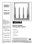
OWNER'S
MANUAL
MODEL NO.
625.384700
Caution:
Read and Follow
All Safety Rules and
Operating Instructions
Before First Use of
This Product.
Reverse Osmosis
Drinking Water System
• Warranty
• How To Install
If you have questions when
installing,
operating
or
maintaining
your
reverse
osmosis
system,
call this
toll-free
number...
1-800-426-9345
• How It Works
• Care Of
• Repair Parts
System tested and certified by NSF International I
to ANSI/NSF Standard 58 for the reduction of the
c a ms spec fed
SAVE THIS MANUAL
PRINTED
IN U.S.A.
on the performance
_/'=.,.,==_
data sheet.
Sears, Roebuck and Co., Hoffrnan Estates, IL 60179 U. S. A.
- WARRANTY1
I
=
li
I
I
/liJ
I
Ill
li
I
I
_
I
Ill
I
FULL WARRANTY
ON REVERSE OSMOSIS
DRINKING WATER
(except filter cartridges and R. O. membrane)
/
I
lill_
SYSTEM
=
=
I
For one year from the date of purchase, when the Reverse Osmosis Drinking Water System is installed
and maintained in accordance with our instructions, Sears will repair, free of charge, defects in material
= and workmanship, except filter cartridges and the R. O. membrane,
I
I
I
II
t
I
!
TO OBTAIN WARRANTY
SERVICE, SIMPLY CONTACT
THE NEAREST SEARS SERVICE CENTER
THROUGHOUT
THE UNITED STATES. This warranty applies only while this product is in use in the
United States.
!
I
I
I
Thiswarrantygi_es__uspe_ifi_Iega_rights_andy_umayha_e_therrightswhich_aryfr_mstatet_state_
I
i
I
Sears,
Roebuck
and Co., D/817 WA, Hoffman
Estates,
IL 60179
i
I_ .............................
SEARS INSTALLATION
_1
POLICY
SEARS INSTALLATION
All installation
labor arranged
by Sears shall be performed
in a neat, workmanlike
manner
in accordance with generally
accepted
trade practices.
Further, all installations
shall comply with all local laws,
codes, regulations,
and ordinances.
Customer
shall
also be protected
during installation
by insurance
relating to Property
Damage,
Workman's
Compensation and Public Liability.
WARRANTY
In addition
to any warranty
extended
to you on the
Sears merchandise
involved,
which
warranty
becomes effective the date the merchandise
is installed,
should
the workmanship
of any Sears arranged
installation
prove faulty within one year, Sears will,
upon notice from you, cause such faults to be corrected at no additional
cost to you.
- SAFETY GUIDES • Read all steps and guides carefully
before installing and using your reverse osmosis system. Follow
all steps exactly
to correctly
install.
Reading
this
manual
will also help you to get all the benefits from
the reverse osmosis system.
•
The reverse osmosis system works on water pressures of 40 psi (minimum)
to 100 psi (maximum).
If
your house water pressure
is over the maximum,
install a pressure
reducing
valve in the water supply
pipe to the reverse osmosis
system.
•
Do not install the reverse osmosis
system outside, or in extreme hot or cold temperatures.
Temperature of the water supply to the reverse osmosis system must be between
40°F and 100°F. Do not install
on hot water.
•
Do not attempt to use this product to make safe
drinking water from non-potable
water sources. Do
not use the system on microbiologically
unsafe water, or water of unknown
quality without adequate
disinfection
before or after the system.
•
Read the other limits (pH, hardness, etc.) in the
specifications
and be sure your water supply
conforms. Also see "Water Supply"
on page 3.
•
Check with your local public works department
for plumbing
and sanitation
codes. You must follow their guides as you install the system. Follow
your local codes if they differ with guides in this
manual.
•
The reverse osmosis membrane
contains
a preservative
for storage and shipment.
Be sure to purge
as instructed
on page 9 before using product
water.
2
- TABLE OF CONTENTS
Where To Install the RO System
........
Tools and Materials
Needed
...........
Installation
Cold
Steps
Water
4
4
....................
Supply
..................
Storage
Tank,
Tubing
How
5
....
Pressure
the RO System
Dimensions,
Test, Purging
Works
....
9
...........
10
...................
Specifications
11-14
............
Repair Parts .........................
Remote Installation
Locations
7
Connections
- continued
Care of RO System
6
6- 7
......................
Steps
Sanitizing,
5- 9
Drain Adapter
.....................
Faucet
............................
RO Assembly
Installation
-
15
16-17
18
.........
8
- WHAT YOUR REVERSE OSMOSIS SYSTEM WILL DO Your Reverse Osmosis
(RO) Drinking
Water
is a water treatment
unit. It uses household
System
water
RO membrane.
The postfilter
removes
any tastes
and/or
odors that may remain
in the water, after
passing
through
the RO membrane,
and just before
going to the RO faucet. To prevent
water waste, an
automatic
shutoff valve closes when the RO faucet is
pressure
to reverse a natural physical
process called
osmosis. Water, under pressure,
is forced through
a
semi-permeable
membrane
where minerals
and impurities are filtered out. Clean drinking water goes to
the faucet or storage, while minerals
and impurities
are sent to the drain with RO waste water. The minerals and impurities
are measured
solved solids (TDS).
in water
closed
and the storage
tank
is full.
Your reverse osmosis system gives you a continuous
supply
of sparkling
clear, delicious
water for drinking, cooking
and other uses. Foods will look and
taste better too. Having high quality RO product water at your fingertips
eliminates
the need to buy
bottled water. The storage tank holds over 2 gallons
of RO product
water for your needs.
as total dis-
The system
includes
replaceable
pre and postfilter
sediment-carbon
cartridges.
The prefilter
removes
sand, silt, dirt, rust particles,
other sediments,
and
chlorine from the water supply before it can enter the
- BEFORE YOU BEGIN TO INSTALL THE RO SYSTEM FOR OPTIMUM
PERFORMANCE
YOUR KENMORE REVERSE OSMOSIS
SYSTEM SHOULD BE
INSTALLED
ON SOFTENED
WATER.
CAUTION:
A refrigerator
properly
when connected
tem.
months.
See the RO care guide
on page
14.
Check Parts Included:
Unpack
the carton
and remove the RO system. In addition
to the assembled
RO and the storage tank, the system includes the
parts illustrated below, a separate length of tubing,
and this manual.
icemaker may not operate
to a reverse osmosis
sys-
Check Your Water Supply: The cold water supply to
the RO system must be within certain quality limits.
See the specification
table on page 15. If supply water
is not within limits, the RO system can not make
product water as it should and reduced
RO membrane life will result.
FIG. 1 ]
WASHERS &
SCREWS
HANGER
RO PRODUCT
WATER FAUCET
WATER
SUPPLY
FITTING
Trained
salespeople
at Sears can arrange
for a free
water analysis.
The analysis will tell you if other water supply
treatment
is needed
before going to the
RO system.
_=a_,?_
13 DRAIN
I
CAUTION:
Chlorine
RO membrane.
Most
in the water will destroy the
cities add chlorine to the wa-
©
TEFLON
TAPE
ter supply to kill bacteria. The prefilter removes
chlorine up to the limits shown in the specifications
before it enters the RO membrane.
It is important
to replace the prefilter
cartridge
at least every 6
TUBING
ADAPTER _'
3
PTER t
)
- WHERE TO INSTALL THE RO SYSTEM The RO assembly
and storage tank is designed
for
installation
under the sink, usually in the kitchen or
bathroom.
The RO assembly
mounts
on a wall sur-
in any remote
location
from the faucet, observing
safety guides on page 2. You do need a nearby water
source and drain point (see page 18).
face, or can lay on the cabinet floor next to the storage
tank. Hanger washers and wood screws are included
for cabinet
wall mounting.
The RO product
water
faucet installs on the sink, or on the countertop
next
to the sink (pages 6 and 7).
Note: Tubing
lengths
allow
for the removal
Water
the RO assembly
and storage
To provide
supply
water
for tubing
5.
to the
RO
connec-
Drain Point: A suitable drain point is needed for reject water from the RO membrane.
A floor drain,
laundry
tub, standpipe,
sump, etc., is preferred,
as
shown in the remote locations
drawing,
page 18. A
sink p-trap drain adaptor
is included
to install where
codes permit, as an optional drain point (page 6).
of the
assembly
from the hanger washers
for servicing.
If
tubing
lengths
are shortened
for neater
appearance, it may be necessary
to keep the assembly
on
the hanger
washers
for service.
You can also locate
Supply:
system inlet, install pipe fittings
tion, as typically
shown on page
tank
RO
I RG.
2
]
/
_--x
_wate_:f°duuctt
drain adapter
sink drain
p -trap
RO Assembly
- TOOLS AND MATERIALS NEEDED •
adjustable
wrench,
standard
pliers, and larger
adjustable
jaw pliers or pipe wrench to fit sink drain
slotted
Phillips
plumbers and putty
head
•
pipe joint compound
(thread seal) approved
for
use on potable water supplies
•
electric drill and bits, if hole is needed for the RO
screwdrivers
faucet,
page
6 and
7
- 6 STEPS TO INSTALL STEP
5
1: - Install
Cold Water
STEP 2: - Install
Drain
STEP 3: - Install
Faucet
Supply
Adapter
- pages
fittings
- page
6 and
- page
STEP
4: - Install
STEP 5: - Install
ing Connections
6
RO Assembly
Storage
- page
STEP 6: - Sanitizing,
page 9
7
4
Tank
8
Pressure
- page
Make
7
Remaining
Testing,
Tub-
Purging
-
- STEP 1: INSTALL COLD WATER SUPPLY FITTING Check and comply with local plumbing codes as you plan, then install a cold feed (supply) water fitting. The
fitting must provide a leak- tight connection to the RO 1/4" tubing (see FIG. 8, page 8). A typical connection
using the included water supply fitting is shown in FIG.3 - A below. An optional connection, using standard
plumbing fittings (not included), is shown in B.
A.
WATER SUPPLY
FITTING
B. OPTIONAL
shown)
1. Close the house main water shutoff valve and open
faucets to drain water from the sink cold water pipe.
2. Remove
nut that connects
cold water
plumbing.
the cold water
faucet
supply
4. Thread water supply fitting onto pipe and reconnect
nut to bottom of fitting.
A.
B.
WATER SUPPLY CONNECTION
(using Included water supply fitting)
and open
WATER SUPPLYTYPICAL
(using compression
CONNECTION
fitting)
- parts not included cold water
faucet stud
water supply fitting
RO inlet (see step
2, on tubing
page 8)
1/4"
to
f
H
H
ii
cold water
shutoff
_;ter
cold /
._/
f
\
type
Complying
with plumbing
codes, install a fitting on
the kitchen cold water pipe to adapt 1/4" OD tubing.
A typical
connection
is shown
in figure
3B. If
threaded
fittings are used, be sure to use pipe joint
compound
or Teflon tape on outside threads.
fitting that connect to the cold water pipe.
1
FIG. 3 |
J
(compression
Note: Be sure to turn offthe water
a low faucet to drain the pipe.
to
3. Use pipe joint compound or Teflon tape on cold water
faucet stud threads and on the male threads of the water
supply
PIPE FITTINGS
1/4" compression
fitting
f.-_
cold _
water
pipe
cold water
shutoff
5
insert
1/4" tubing to
_'-_t
RO inlet (see step
_
2, on page 8)
"
- STEP 2: INSTALL DRAIN ADAPTER • Note: Running
the drain tubing directly to a floor
drain, sump, standpipe,
laundry
tub, etc., as shown
on page 18, is preferred.
However,
if that is not possible or practical,
the included
drain adapter
installs
in the sink drain pipe, always above or ahead of the
p-trap
(FIG. 4). Be sure to comply with your local
plumbing
codes. Other drain pipe fittings, in addition to the adapter, may be needed.
FIG. 4
]
• The drain adapter fits 1-1/2" sink drain pipe.
• The adapter installs directly onto the sink tailpiece
as typically
shown in FIG. 4 and 5.
• Locate so drain tubing from the faucet (installed in
step 1, page 8) makes a straight run to the adapter,
without dips, loops, low spots or kinks.
Note: Consult a plumber
plumbing
procedures.
if you are not familiar
P-trap
FIG. 5 ]
with
_nn
/
1. Use a ferrule and nut to assemble
the drain tubing
connector to the drain adapter
(FIG. 5). Turn the connector to about 45 ° from the 12:00 position,
as shown
(to 10:00 or 2:00 position
as needed).
Tighten the nut
securely.
2. Carefully
disassemble
the sink drain
pipe
clean the tailpiece to assure a leak-tight
fit.
and
ferrule 0
3. Install the drain adapter
onto the sink tailpiece,
using a ferrule and nut. Snug the nut, but do not
tighten.
Note: If needed, to make fit, you can cut to shorten
the unthreaded
end of the adapter. Do not cut too
short so the adapter will make a leak-tight seal with
the connecting fitting.
4. Assemble
the p- trap to the drain
er drain pipe fittings as required
complete
the drain run.
5. Tighten all connections,
break plastic fittings.
adapter,
(check
%
cut, if
needed
and othcodes) to
but do not overtighten
2:00
drain tubing
connector
10:00_
and
- STEP 3: INSTALL FAUCET A. PREPARE
MOUNTING
HOLE
CAUTION:
To avoid damaging
a sink beyond
repair, consult
a qualified
plumber
or installer
for
guides to drill holes in porcelain
or stainless steel.
1. Select 1 of the following
places for the faucet. Be
sure it will fit flat against
the surface,
and there is
space underneath
for tubing (see FIG. 8, page 8).
Use an existing sink top hole for a spray hose or
other faucet. A 1" to 1-1/4" diameter
hole is needed.
0
Drill a new
sink.
t
Drill a new
hole in the countertop
2. If drilling
ter hole.
next to the
is needed,
make
the 1" to 1-1/4"
diame-
3. Place plumbers
putty around the drilled hole (FIG.
6) to prevent
water leakage around
the base of the
faucet.
hole in the sink top.
6
- STEP 3: INSTALL FAUCET (cont.)B. ASSEMBLE
FAUCET
FIG. 6 ]
1. If not already assembled,
install the rubber washer,
spacer, flat (or lock) washer
and hex nut onto the
threaded
faucet stud.
insert spou_
2. Apply Teflon tape to
Turn the tubing adapter
stud and hand tighten,
BE CAREFUL
NOT TO
the end of the faucet stud.
with a blue collet onto the
then wrench
1/4 turn only.
CROSS THREAD.
remove tubing piece
3. Wet the o-ring seals on the faucet spout. Then, remove and discard the short piece of tubing from the
faucet body and insert the spout in its place.
4. CONNECT
TUBING
TO FAUCET
AS FOLLOWS.
a. Take the separate
length of 3 / 8" black tubing put
an end through
the larger hole in the rubber washer. Slide the end onto the larger barb fitting on the
bottom of the faucet.
Note: To soften
end of tubing,
ASSEMBLEDHOLE
IN
MOUNTING
rubber
washer
hold under hot water.
_
b. Route 1/4" red tubing from RO up through
the
sink hole and slide end onto the smaller barb fitting
(heat end if needed)
on the faucet.
=_,=_/spacer
°ek
c. Route 3/8" blue tubing from RO up through the
sink hole and push end all the way into the tubing
adapter
fitting on the bottom of the faucet. Pull on
putty
_.,_
hex nut
_._
tubing adapter
blue collet
the tubing to be sure it's held firmly in the adapter
fitting. See pages 12 and 13 for tubing connection
instructions.
5. Lower
the faucet
into the sink or countertop
6. On the underside
of the sink
the large steel washer
between
and the spacer on the faucet
view). Then, turn the hex nut
tighten.
Tighten the hex nut
move, but do not overtighten
hole.
steelwasher
.J
_
or countertop,
insert
the mounting
hole
stud (see assembled
up to the spacer and
so the faucet cannot
and break the faucet.
_
holein sink or
countertop
_1-[
114" red tubing
to drain point
_-_-//
\
\/
/_
YJ
3/8"blue /
tubing
- STEP 4: INSTALL RO
ASSEMBLY Hang the assembly
on the included
hanger
or lay on the cabinet floor, as desired.
I
FIG. 7 ]
hanger
washer (2)
screw (2) _(_)
TUBING FROM
RO SYSTEM
I'_,_
I_
10-1/2"
washers,
1. Refer to FIG. 7 for wall mounting.
Hold the assembly up to the wall surface and mark locations
for the
hanger washers.
Indicator
marks on top of the bracket are the needed
10-1/2"
apart.
15-1/2"
min.
up from
floor
2. Install hanger washers
at least 15-1/2" up from the
cabinet floor, allowing
room to remove sumps from
filter heads. Wood screws
are provided,
or obtain
other fasteners
as needed.
7
- STEP 5: INSTALL STORAGE TANK,
MAKE REMAINING TUBING CONNECTIONS
1.
CONNECT
DRAIN
TUBING,
FAUCET
TO
scribed
DRAIN ADAPTER:
Referring
to FIG. 8, run the loose
section
(connected
to faucet barb fitting) of black
3 / 8" tubing from the faucet to the drain adapter, with
a black collet, installed
on page 6. Cut this tubing as
needed
to route in as straight
of a run as possible,
without
loops, dips, low spots or kinks. Cut the end
of the tubing square. Then push all the way into the
fitting. Pull on the tubing to be sure it's held firmly
in the adapter
fitting. See pages 12 and 13 for tubing
connection
instructions.
2. CONNECT
TUBING
TO WATER
SUPPLY:
13.
3. Move the storage tankinto
place next to the RO assembly. You can stand the tank upright,
or lay it on
side. Apply no more than 2 wraps of Teflon tape to
the threads on the nipple at the top of the tank. Hand
tighten
the other included
tubing
adapter
fitting
with the yellow
collet onto the tank nipple,
then
wrench
1/4 turn only.
BE CAREFUL
NOT TO
CROSS THREAD.
4. Run the 3/8" yeUow tubing to the fitting installed
in step 3. Be sure the end of the tubing is cut square,
and insert all the way into the fitting. Again, pull on
the tubing to be sure it's held firmly in the fitting.
Con-
nect the feed (green) tube to the water supply fitting
installed on page 5. Connection
to the fitting is as de-
I FIG. 8 I
in Fig. 11, page
-
TYPICAL UNDERSINK INSTALLATION
RO product
water faucet
- 3/8" black tubing, to
larger barb on faucet
water supply
Note: See note on page 4
regarding tubing lengths.
yellow collet
tubing adaptor
8
- STEP 6: SANITIZING,
PRESSURE TESTING & PURGING
SANITIZING
6. If needed
fresh water.
Sanitizing
is recommended
upon installation
of the
RO system, and after servicing
inner parts. It is important for the service person to have clean hands
while handling
inner parts of the system.
CAUTION:
Be sure
to remove
attack
the RO membrane
to the RO is turned
to relieve pressure.
8. Slowly
off,
PRESSURE
1. Do the preceding
pressure testing.
2. Open the water
supply
shutoff
3. Open the main water supply
house faucets to purge air from
faucets when water runs smooth.
PURGING
procedures
valve
12. Turn off the water
supply
to the RO.
by locking
the lever
head
upward
supply
and run
to the RO.
13. Be sure your hands are clean. Then, repeat steps
1 - 5 and 7, only replace all cartridges.
Imp_'tant:
Refer to FIG. 9, page 11, and to page 12
when replacing
cartridges.
The prefilter (left side)
cartridge
has light gray coloring, and the postfilter
(right side) has blue coloring.
Also
4. In about 2 hours, pressure
RO system. Then, carefully
nections
for water leaks.
found.
before
will start to build in the
check all fittings and conCorrect leaks if any are
to the RO.
valve and several
the system.
Close
Note: When the system is first pressurized,
water
may "spurt"
from the faucet airgap hole until air is
expelled
from the RO system.
RO MEMBRANE
1. Allow the storage
tank to fill for about 4 hours.
Then open the RO faucet until the tank is empty and
flow stops.
Important
purging instructions:
The RO cartridge
contains
a food grade preservative
that should
be removed before using water from the system. The preservative
will give product
water an unpleasant
taste
and odor.
Repeat steps I and 2 to purge
make product water for use.
the water
11. After the 20 minutes open the RO faucet
water until the bleach odor is gone.
TESTING
sanitizing
open
on the prefilter
10. Allow water to circulate through
the RO system
until you smell the bleach odor. Then close the faucet
and allow the RO to stand idle for 20 minutes.
4. Remove
the postfilter
sump, turning
to the left.
Take the cartridge
from the sump and place in the
plastic bag. Replace the sump and tighten securely.
and cartridge.
bag.
replace the sump
securely.
9. Open the RO faucet
against the spout.
in the RO cap. Replace the
while turning
to the right
5. Remove
the preffiter
sump
place this cartridge
in the clean
plastics.
7. Carefully
and tighten
2. Referring
to FIG. 9, page 11, press inward while
turning the RO cap to the left (_) to remove from the
bracket/membrane
housing.
Remove
(use pliers)
the RO cartridge
from the housing.
Place the cartridge in a clean plastic bag.
3. Be sure the o-ring sealis
RO cap and push inward
(_) to lock.
sump with
1" from the
top. Add
1.0 ounce
of chlorine
(ordinary
5.25%
household
bleach...Hllex,
Clorox, etc.) and mix in the
water. Do not add chlorine first. Concentrated
it will
and both filter cartridges as follows, before sanitizing. Chlorine will destroy
the RO membrane
cartridge.
1. Be sure the water supply
and the RO faucet is open
to clean, flush the prefilter
Then fill with water to about
-
the storage
2. Close the RO faucet and allow the tank to fill again
for 4 hours.
Then open the RO faucet and empty
again.
tank 6 times. Then the RO system
9
is ready to
- HOW YOUR REVERSE OSMOSIS
PREFILTER
product
quality
Water from the cold supply pipe enters the RO assembly prefilter first (FIG. 8 and schematic
below).
OSMOSIS
To comply with plumbing
into the faucet drain water
SHUTOFF
The storage tank holds up to 2.3 gallons of product
water.
A diaphragm
inside the tank keeps
water
pressurized
to about 30 psi, when the tank is full, to
provide
fast flow from the RO faucet. The tank when
empty, is pressurized
to 5 - 7 psi.
valve
(FIG. 10) is located in the outlet
Water flow through
the RO membrane
is regulated
by the flow control. It maintains
the desired flow rate
to obtain
the highest
quality
drinking
water. The
flow controlis
located in the end of the 1 / 4" red drain
tubing, at the RO housing
drain port. A small coneshaped screen fits over the end of the flow control to
help prevent
plugging
with drain water sediments.
but before going to the
through
the post filter.
carbon type filter. Any
are removed
from the
PRODUCT
WATER
FAUCET
.
BLUE
,,ele
YELLOW
REVERSE
II./1' d_a,_nt_oOlW
rl]_ _'w
[' l&l &
&t
'*,I
_
SCHEMATIC
.q.._
_
.,__.
.__._
f
_
-- _t=-- -- --
drain
1
l,_p
AUTOMATIC [_
SHUTOFF
,,,,e=
[_
GREEN
REFILT:
IN
10
OSMOSIS
RO MEMBRANE
check
I_I:___ " ;_
f
valve_._O
_= - -- _.--
PRODUCT WATER
WATER
end of
FLOW CONTROL
POST FILTER
gravity
ASSEMBLY
the RO housing,
opposite of the cap. The check valve
prevents
a backward
flow of product water from the
storage tank. A backward
flow could rupture
the RO
membrane.
TANK
'1
codes, an air- gap is built
connection.
CHECK VALVE
A check
,,la=_l,,.
high
To conserve water, the drinking water system has an
automatic
shutoff system. When the storage tank has
filled to capacity,
and the drinking
water faucet is
closed, pressure
closes the shutoff to stop flow into
the RO. Pressure
in the storage tank is about half of
the water supply
pressure.
After drinking
water is
used, and pressure
in the system drops, the shutoff
opens to allow water flow again.
The cartridge inside of the RO housing
is a tightly
wound
special membrane.
The membrane
removes
the dissolved
solids and organic matter when water
is forced through
the cartridge.
High quality product
water (about I ounce per minute) exits the RO housing and goes to the storage tank or to the postfilter
and RO faucet. Reject water, with the dissolved
solids and organic
matter, is routed through
the flow
control and to the drain.
After leaving the storage tank
RO faucet, product water goes
The post filter is an activated
remaining
tastes and odors
Taste-free,
odor-free,
clean,
water is available
for use.
The sink or countertop
faucet has a hand operated,
spring-loaded
closed lever to prevent
the waste of
drinking
water. You can also keep the faucet open by
pushing
upward
on the lever and locking it against
the faucet spout.
(RO) CARTRIDGE
STORAGE
water.
drinking
FAUCET
The prefilter
has a replaceable
sediment
cartridge
with activated
carbon in its composition.
The cartridge (10 micron) removes sand, silt, dirt, other sediments, and up to the ppm of chlorine
shown in the
specifications
from the feed water. Chlorine
will destroy the RO membrane.
Filtered,
clean, chlorinefree water flows from the prefilter,
to the RO membrane cartridge.
IMPORTANT...
See pref!lter maintenance,
page 11.
REVERSE
SYSTEM WORKS -
I
•
- CARE OF YOUR REVERSE OSMOSIS
To keep your reverse osmosis system operating
and
producing
high quality water, you must make sure
supply water is always within the limits shown in the
specifications.
Good supply
water helps to assure
longer life from the RO membrane
cartridge,
prefilter
and postfilter
cartridges.
However,
each of these will
wear out in time and need replacement.
SYSTEM -
Note: The prefilter cartridge
and end caps. The postfilter
change,
*Note: Use a lubricant
water supply.
approved
FIG. 9
_
This reverse osmosis system contains a replaceable
treatment component
critical for effective removal of
total dissolved
solids. The water should be tested
periodically
to verify the system is performing
satisfactorily.
If the RO assembly
is wall mounted,
to replace parts with the assembly
for use on a potable
mounting(2)
washers
(RO cartridge
o-ring seals on
this end)
you may be able
left on the wall. If
not, simply lift the RO assembly
from the mounting
washers
and lay on the cabinet floor when replacing
the prefilter and post filter cartridges
and RO membrane.
cartridge
o
posffUter
(blue)
Note: To prevent
spillage,
place a container
under
the RO assembly,
or put the RO assembly
in a container to catch the water.
o-ring seal
CAUTION:
Before disconnecting
parts, be sure to
close the water supply valve to the RO.
PREFILTER AND POST
CARTRIDGES
has light gray netting
has blue. Do not inter-
o-ring
seal
l
RO cap
sump
FILTER
Turnsumpsinthe
direction of the arrow
to remove. Turn
You must replace the pref!lter cartridge
often to protect the R O membrane from being destroyed by chlorine,
and/or from plugging with sediments
in your water
supply. If the water supply contains both chlorine
and sediments,
replace the prefilter cartridge at least
every 6 months of product
water use. Replace more
often than 6 months if it begins to plug with sediments.
opposite way to install
and tighten.
RO MEMBRANE
The life of the RO membrane
cartridge
depends
mostly on the pH of the supply water to the RO system (see specifications).
Cartridge
life is shorter with
higher pH. For example, if supply water pH is from 6.8
to 7.7, the cartridge may last for well over 1 year. However,
cartridge life may be as short as 6 months if the pH is as
high as 8.5 to 10. Higher pH weakens
the cartridge
membrane
and causes pin- hole leaks.
If the water has sediments
only, with no chlorine, you
may notice a slower making of product
water as the
prefilter collects the sediments.
When this occurs, replace the prefilter cartridge.
Also replace the post filter
cartridge.
To replace
the filter
1. Turn off the water
to relieve pressure.
cartridges
supply
It's time to replace the RO cartridge
when the production
rate and/or
quality of product
water drops.
Product water may begin to taste different or bad, indicating
solids and organics are passing
through
the
RO membrane.
To be sure it is the RO cartridge,
replace the prefilter and postfilter
cartridges
first.
(see FIG. 9):
and open the RO faucet
2. Remove (turn to the left) both sumps from the filter
heads. Be careful...the
sumps are full of water.
3. Remove and discard the inner cartridges in a proper manner. Flush the insides of the sumps with fresh
water. Do not lose the large o-ring seals.
4. Insert new cartridges, and with lubricated*
in place, turn on and tighten the sumps.
CARTRIDGE
To replace
the RO cartridge
1. Turn off the water
to relieve pressure.
o- rings
supply
(see FIG. 9):
and open the RO faucet
continued
11
- CARE OF YOUR REVERSE OSMOSIS SYSTEM 2. Press
(_)
inward
to remove
while
turning
the RO cap to the left
from the bracket/membrane
5. Inspect the o-ring and
or otherwise
damaged.
drain port.
housing.
3. Use a pliers, or heavy wire made into a hook,
pull the RO cartridge
from the housing.
to
Note: Sanitizing is recommended
after servicing
ner parts of the system (see page 9).
in-
FIG. 10 ]
TO
DRAIN
A
flow (control) insert
5. Lubricate
the RO cap o- ring seal if dry. Replace the
o-ring into the cap. Press inward
on the cap while
turning to the right (_)to lock. The cap will not go on
if the RO cartridge
is not fully seated inward.
the flow control
7. Purge the RO membrane
tions on page 9.
FLOW CONTROL
The
RO
flow
tain
and
screen
cartridge
AND
l/4"tubi, ng _"1
(see below).
following
control
SCREEN
ball
spring_
o-ring_
and screen
cap _check
,i
valve
(FIG. 10):
TUBING
tubing.
the flow control
Be sure the center
CONNECTION
(all push-in
1. At the drain connection,
depress
the collet (FIG.
11) with a finger while carefully pulling on the drain
tubing to remove.
2. Remove
_screen
instruc-
Whenever
servicing
the RO system,
check the flow
control to be sure the small hole through
it is clean
and unrestricted.
Also check and clean or replace the
cone-shaped
screen in front of the control. The RO
membrane
cannot discharge
minerals
and impurities to the drain if the flow control plugs with foreign
material.
If this happens,
it only takes a short time for
the membrane
to foul and become useless.
flow
]
o-ring seal Jdrain
flow control is vital for proper
operation
of the
membrane
cartridge.
The control
keeps water
through
the membrane
at the needed rate to obthe best quality product
water.
To clean/replace
cut
the
6. Be sure the flow control is in the end of the tubing,
then push all the way into the fitting.
4. Install the new cartridge,
end with o-ring seals inward. Work back and forth to get all the way in (end
of cartridge
about 1-1/4" in from end of housing).
6. Check
collet. Replace if worn,
Carefully
replace
into
fitting
locations)
This RO system includes
push-in
fittings for quick
tubing connection
at most locations.
If working
with
the fittings, do the following.
from the end of the drain
hole is clean.
Connection
(FIG. 11):
3. Check the drain tubing to be sure it's clean. Then
insert the cleaned or new flow control into the tubing.
1. Use a sharp
square.
4. With a small screwdriver
carefully remove the collet and o-ring from the drain port. Use a small needle-nose pliers or tweezers
to remove the screen from
the drain port. Thoroughly
clean or replace with a
new screen. Install pointed
end down.
2. Inspect the end (about 1") of the tubing to be sure
there are no nicks, scratches
or other rough spots. If
needed,
cut the tubing again.
Note: Visually
rectly.
check
to be sure it is positioned
cutter
or knife
to cut the end
of tubing
3. Push tubing through the collet and all the way into
fitting. Full engagement
is 11/16" for 1/4" tubing,
and 3/4" for 3/8" tubing.
cor-
continued
12
- CARE OF YOUR REVERSE OSMOSIS
TUBING
CONNECTION
AUTOMATIC
(continued)
If tubing other than tubing supplied
with the system
is used, be sure it is of high quality, exact size and
roundness
with a smooth
surface.
'
k_ ....
I
./
screw (4)
_- _
Tee Fitting,
1/4" NPT x 3/8"
Tube
collet ..._ [_
-7
I
SERVICE
f<_>_
FIG. 12 ]
Tubing correctly cut and connected
cut tubing s_uare
SHUTOFF
If the shutoff assembly
requires
service, be sure to
reassemble
parts exactly as shown in FIG. 12, and to
reconnect
tubing as shown on pages 10 and 16.
To Disconnect
Tubing: Push the collet inward
and
hold with a finger while pulling the tubing out.
FIG. 11 ]
SYSTEM -
SHUTOFF
ASSEMBLY
I
I
end of tubing round and
smooth, with no cuts,
nicks or flat spots
'
11116" (1/4" tubing
engagement
r11- 3/4. (3/8. tubing)
diaphragm
O
Replacing collet end
o-ring seal
collet (depress to
remove tubing)
Push o-ring seal in to
bottom of port, then
follow with collet.
tubin
plunger (_
tting
collet
diaphragm
Changing
CoUet and O-ring
1. With a small
screwdriver
O
(FIG. 11):
remove
the collet
and o-
ring from the fitting.
2. Be sure the port is clean, then lubricate
the o-ring seal to the bottom of the port.
3. Push
r
I
I
I
I
[
the coUet inward
and insert
int° OUT P°rt'_
_,
,, _
Male Elbow, I/8
_
until it locks in place.
CAUTION
DO NOT USE VINEGAR
OR OTHER ACID
BASEDCLEANERSONTHISROSYSTEM.
THEY
WILL DEGRADE SOME RO SYSTEM PARTS. ALWAYS USE SOAP AND WATER.
I
I
I
I
I
J
1
This reverse osmosis system contains a replaceable
treatment component critical for effective removal
of total dissolved
solids. The water should be
tested periodically to verify the system is performing satisfactorily.
I- ........
Male Connector,
/ 1/8"NPTxl/4"Tube
..._... /
.PTx 1/4"Tob+ng
Bm.._
t
I
]
I
I
[
Elbow fitting turns__/_'_
I
I
[
I
[
-I
13
collet
- CARE OF YOUR REVERSE OSMOSIS SYSTEM REVERSE
OSMOSIS
SYSTEM CARE
MODEL NO. 625.384700
GUIDE
1. AT LEAST every 6 months, replace the prefilter and postfilter cartridges. Clean or replace the flow control and
screen.
2. Replace the RO membrane cartridge when the percent rejection of total dissolved solids (TDS) is less than shown
in the specifications (see B, below).
If any of the following occur before the 6 months, replace as directed.
A. Slow Making of Produot Water: Replace the prefilter cartridge.
If the production rate does not improve, replace the post filter cartridge and RO membrane cartridge.
C. Ch/orine Tasteand/or Odor: Replace the prefilter,post filter and
RO membrane cartridges.
B. High Total Dissolved Solids (TDS) in Product Water: You can
get a free TDS test through some Sears retail stores or service
departments. If the store or service department does not have a
TDS meter, you can send treated and untreated water samples to
a water analysis lab for testing. It is important to test both the
treated and untreated water to determine system performance. If
the TDS is not within the system's performance guidelines,
replace the prefilter, post filter and RO membrane cartridges.
OTHER TROUBLESHOOTING
PROBLEM
CAUSE
CORRECTION
Chlorine taste and/or
odor in the RO product
water
The ppm of chlorine in your water supply
exceeds maximum limits, and has destroyed the RO membrane.
Ifthe water supply contains more than 2.0 ppm of chlorine, additional filtering of the water supply to the RO is needed. Correct
this condition before doing maintenance on the RO system.
The prefilter is no longer removing chlo- Replace the prefilter, post filter and RO membrane cartridges,
rine from the water supply.
flow control, and screen.
Other taste and/or odor
System makes product
water too slowly
Postfilter expended.
RO membrane cartridge expended.
Replace the post filter cartridge. If taste and odor persists, replace the prefilter cartridge, RO membrane cartridge, flow control, and screen.
Contamination
Use sanitizing procedures. Replace the post filter cartridge.
in product water storage.
Water supply to the RO system not within Increasewaterpressura, praconditionthewater, etc., as needed
specifications.
to conform before doing maintenance on the RO system.
Prafilter or RO membrane
plugged with sediments.
cartridges
Replace the prefilter cartridge. If rate does not increase, replace
the postfilter cartridge, RO membrane cartridge, flow control,
and screen.
System makes
lower
amount of produot water
than usual
Storage tank air-charge lees than 5 - 7 Open RO faucet and drain tank until flow slows to a drip, Keep
psi.
faucet open and check tank pressure. If low, pressurize to 6 psi.
Close faucet to refill the tank.
High tota/ dissolved so/ids (TDS) in product watar
WatersupplytotheROsystemnotwithin
specifications,
Incraase water prassure, precondition the water, etc., as needed
to conform before doing maintenance on the RO system.
RO membrane cartridge expended.
Replace the prefilter, postfilter and RO membrane cartridges,
flow control, and screen.
Drain side of faucet airgap (3/8" tubing)
plugged, restricted, or incorrectly connected to drain point.
Inspect and eliminate restriction or plug. Refer to installation
instructions for proper drain connection.
Water leaking from fauoet airgap hole
Continual
drain
water flow to ; Check valve or automatic shutoff assembly plugged, restricted or parts worn
Note: Sanitizing
is recommended
after servicing
inner
14
Clean, repair or replace as needed.
parts
of the system(see
page
9).
- DIMENSIONS and SPECIFICATIONS -
15"
Metric
Supply water pressure limits ........................
40 - 125 psi
280 - 860 kPa
Supply water temperature
40 - 100 °F
5 - 40°C
limits .....................
Maximum total dissolved solids (TDS)
...............
2000 ppm
Maximum water hardness @ 6.9 pH .................
Maximum iron, manganese,
Chlorine in water supply (max. ppm)
Supply water pH limits (pH)
10 gpg
hydrogen sulfide .........
0
................
2.0
........................
Product (quality) water, 24 hours _
4 - 10
.................
Waste water per gallon of product water Q ...........
Percent rejection of TDS, minimum
Storage tank capacity (max.)
(new membrane)
.......................
O
5 gal.
18.9 liters
5 gal.
18.9 liters
90 - 95
2.3 gal.
Automatic shutoff control ...........................
8.7 liters
yes
_) feed water supply at 50 psi, 77 ° F, and 750 TDS
Quality water production, amount of waste
water and percent rejection all vary with changes in pressure, temperature and total dissolved solids.
15
- REPAIR PARTS Kenmore
Reverse
Osmosis
Drinking
Water System, Model No, 625.384700
1
I"
I
I
I
I
1/4" Tubing _
_10_
U
I
35
_
o-ring seals
I
I
j3
33
.I
!DRA ,
26
t
ADAPTER
!
5
34
21
Bracket!Membrane Housing
PUSH - IN FITrlNGS
]
20
CO et
19
24
I
-9
12
13
23
16
10
- REPAIR PARTS Kenmore
Reverse
Osmosis
Drinking Water System, Model No. 625.384700
Key
NO.
Part
Number
1
7205350
2
7207920
3
7185788
4
42-34702
5
7177175
6
7174965
RO Cap
7
7207881
Elbow, 3/8" NPT x 3/8" Tube (2 req.)
8
7156535
9
Key
No.
Part
Number
Faucet
30
7095030
Cone Screen
Adaptor, 7/16"-24 x 3/8" Tubing
31
7208413
Flow (Control) Insert
Screw, #10-12 x 5/8" (8 req.)
32
7227310
Tee, Feed Adaptor
RO Membrane Cartridge
33
7208489
Drain Adapter
O-ring Seal, 1-7/8" x 2-1/8"
34
7209566
Push-in Fitting Kit, 1/4" ®®
7209574
Push-in Fitting Kit, 3/8" _®
35
9006062
Screw (2 req.)
Head (2 req.)
36
9041700
Hanger Washer (2 req.)
7170246
O-ring Seal, 3-3/8" x 3-5/8" (2 req.)
•
42-34334
Sump Removal Wrench ®
10
42-34370
Filter Cart., T & O Postfilter
•
7161823
Tubing, 1/4" x 20' - white []
11
7156577
Sump (2 req.)
•
7161784
Tubing, 1/4" x 100' - white [] ®
12
7171674
Connector, 1/8" NPT x 1/4" Tubing
•
7157280
Tubing, 3/8" x 20' - white [] ®
13
7171682
Elbow, 1/8" NPT x 1/4" Tubing
•
7161750
Tubing, 3/8" x 100' - white [] ®
14
7112442
Valve Top
•
7227271
Owner's Manual
15
7112434
Valve Center
16
7014979
Plunger
17
7099296
Diaphragm (2 req.)
•
42-34713
White Faucet
18
7112426
Valve Bottom
•
42-34714
Black Faucet
19
7030721
Screw, #10-14 x 1-3/4" (4 req)
•
42-34715
Stainless Faucet
7133838
Shutoff Assembly
20
7208502
Tee, 1/4" NPT x 3/8 Tubing
21
7207899
Elbow, 3/8" NPT x 1/4" Tube (2 req)
•
22
42-34373
Filter Cart., Sed.-
[] includes key numbers 14 through
23
7205326
Storage Tank
24
7207938
Adaptor, 1/4" NPT x 3/8" Tubing
25
7208366
Bracket/Membrane
26
7133634
Check Ball
27
7110385
Spring
28
7116763
O-ring Seal, 7/16" x 5/8"
29
7202344
Check Valve Cap
Description of Part
Description of Part
®
Optional Designer Faucets Available:
[]
Supplemental
T & O Prefilter
( 42-34707
Storage Tank:
Storage Tank, 3.2 gallon
19
[] tubing lengths for remote installations, page 18 (not
included) Direct replacement for colored lengths of
tubing.
Housing
•
not illustrated
®(_ see page 16 for use locations - Note: This o-ring
and collet are for replacement in the bracket/membrane
housing only. They do not fit the other push-in fittings,
key nos. 2, 7, 12, 13, 21 and 24.
® not included
17
- REMOTE LOCATION FOR REVERSE OSMOSIS
REMOTE
SYSTEM -
RO INSTALLATION
(storage
tank not shown)
Possible remote locations for the RO nearby the kitchen or bathroom sink include; (1) a basement area
underneath the sink, and (2) an adjacent room or closet. Longer lengths of tubing may be needed (see parts
list on page 17).
You can run the drain tubing directly to 1 of several suitable open drain points, as shown below, bypassing
the faucet airgap and p-trap drain. This type of drain is the preferred over the p-trap drain adapter. Check
your local codes. Always be sure to provide an air gap between the end of the hose and the drain point.
RO product
water faucet
Note: Tubing colors as
supplied with RO system.
3/8" blue tubing
1/4" green
OPTIONAL DRAIN POINTS FOR REJECT WATER
(
airgap /
STANDPIPE
LAUNDRY
TUB
COLD
red
red
FLOOR
DRAIN
18
tubing
storage
tank
WATER
SUPPLY
19
OWNER'S
MANUAL
MODEL NO.
625,384700
Reverse Osmosis
Drinking Water System
For the repair or replacement
parts you need
Call 7 am - 7 prn, 7 days a week
IIAL__JIIBB IlllJ_
1 - 800 - 366 - PART
(1 - 800 - 366 - 7278)
For in-home
The model number of
your reverse
osmosis
system is found on the
rating decal. This decal is
on the top of the bracket.
major brand repair service
Call 24 hours a day, 7 days a week
1 - 800 - 4 - REPAIR
(1 - 800 - 473 - 7247)
For the location
Sears
When requesting service
or ordering parts, always
provide the following information:
•
•
Product Type
Model Number
Part
Part Number
Description
Repair
Service
of a
Center
in your area
Call 24 hours a day, 7 days a week
1 - 800 - 488 - 1222
Ulmll
For information
on purchasing a Sears
Maintenance
Agreement,
or to inquire
about an existing Agreement
Call 9 am - 5 pm, Monday - Saturday
1 -
- 827 -
55800
SEAR;
America's Repair Speciafists
Sears, Roebuck and Co., Hoffman Estates, IL 60179 U.S.A.
part no. 7227271 (01/13/01)