1
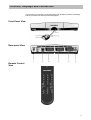
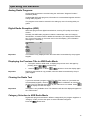
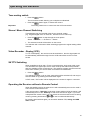
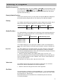
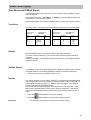
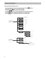
Operating Instructions
Kathrein Satellite Receiver
UFD 346
Order-No.: 260413
Contents
Contents
Operating Controls, Display and Connections............................................................... 3
Front panel with infra-red sensor, rear panel and remote control views ..................................................... 3
Front panel and infra red sensor ............................................................................................................... 4
Rear panel connections............................................................................................................................ 4
Remote control operating buttons ............................................................................................................. 4
Safety Information............................................................................................................. 5
Important locating and setting-up instructions ........................................................................................... 5
Connecting and Setting-up the Receiver ........................................................................ 7
Locating the receiver ................................................................................................................................ 7
Infra-red sensor........................................................................................................................................ 7
Inserting batteries in the remote control .................................................................................................... 9
Operating the Receiver ................................................................................................... 10
Switching on the equipment.................................................................................................................... 10
Switching between TV and radio modes ................................................................................................. 10
Channel selection................................................................................................................................... 10
Analog radio programs ........................................................................................................................... 11
Digital radio reception (ADR) .................................................................................................................. 11
Displaying the previous title in ADR radio mode...................................................................................... 11
Clearing the radio text ........................................................................................................................... 11
Category selection in ADR radio mode ................................................................................................... 11
Volume, balance and tone settings ......................................................................................................... 12
Tone muting switch ................................................................................................................................ 13
Stereo / Mono / channel switching .......................................................................................................... 13
Video-recorder replay (VCR) .................................................................................................................. 13
SAT/TV switching................................................................................................................................... 13
Operating the receiver without the remote control ................................................................................... 13
Channel numbers: changing, sorting and copying................................................................................... 14
Displaying the help menu and program listings ....................................................................................... 14
Tuning a weak video signal .................................................................................................................... 15
Selecting TV Programs ................................................................................................... 16
Setting-up TV programs ......................................................................................................................... 16
The ”Video” menu .................................................................................................................................. 16
Decoder menu ....................................................................................................................................... 18
Program name ....................................................................................................................................... 18
The ”Audio” menu .................................................................................................................................. 19
Selecting Radio Programs.............................................................................................. 20
Selecting radio programs........................................................................................................................ 20
The analog radio menu........................................................................................................................... 20
The "ADR" radio menu ........................................................................................................................... 20
Basic Setting-up.............................................................................................................. 21
Calling-up the basic setting-up menu...................................................................................................... 21
OSD window language ........................................................................................................................... 21
LNB voltage-supply ................................................................................................................................ 22
Program selection .................................................................................................................................. 22
On Screen Display windows (OSD) ........................................................................................................ 22
ADR scan............................................................................................................................................... 22
Oscillator frequency................................................................................................................................ 23
DiSEqC menu ........................................................................................................................................ 24
22 KHz signal......................................................................................................................................... 24
Tone-Burst and DiSEqC signal ............................................................................................................... 25
Remote control command set switching.................................................................................................. 26
Product Features............................................................................................................. 27
Technical Data................................................................................................................. 28
Menu Structures.............................................................................................................. 30
Connection Examples..................................................................................................... 33
2
Controls, displays and connection
Operating Controls, Display and Connections
In this section you will find a short description of all operating controls, the display
and all connections as well as symbol description.
Front Panel View
Rear-panel View
Remote Control
View
3
Controls, displays and connection
Front Panel
Rear Panel Connections
1
Infra-red sensor well
1
Satellite ZF-signal input and LNB voltage-supply output
2
Movable Infra-red sensor
Receives the infra-red signal from the remote control.
As long as the movable infra-red sensor is within the range
of the remote controls infra-red signal it is possible to switch
on a concealed receiver.
2
Infra-red sensor connection (8 pin Western socket)
3
TV scart-socket connection
4
VCR scart-socket connection
5
Decoder scart socket connection
6
12 - 24 V DC connection
3
4
Operating display (red LED)
LED is out when at ”Stand-by”
Program selection buttons
Step-through program selection (forwards and backwards).
Switch from stand-by by pressing both buttons simultaneously.
Switch between TV and Radio modes by pressing both
buttons simultaneously.
Remote control operating buttons
to
Function 1:
On/Off (Stand-by),
Warning!: Mains voltage is still present at receiver!
Function 2:
Reset from setting-up mode to normal operation
Call-up picture tuning menu when receiving a weak
signal
Number buttons 0 - 9 for program selection and
entering the frequencies
Function 1:
Switching between operating instructions
Function 2:
Suppression of the video signal (in set-up mode)
Function 1:
Volume control
Function 2:
Select the individual menu options in Setting-up
mode
Function 1:
Switch to radio mode
Function 2:
Calls-up radio settings menu
Function 1:
Calls-up the help menu
Function 2:
Calls-up ”channel selection” menu,( for changing,
entering and copying )
Function 1:
Program (steps through forwards and backwards)
Function 2:
Modify data in setting-up mode
(with
consecutively)
Not used
4
Function 1:
Saving the selected values
Function 2:
First button for calling-up the individual setting-up
menus (i.e. video setting-up)
Stereo/Mono- (2 Channel) Switching
Function 1:
Calls-up TV/SAT-mode
Function 2:
Calls-up video-setting-up menu
(with
consecutively)
consecutively)
Function 1:
Muting switch
Function 2:
Calls-up Audio-settings menu
(with
(with
consecutively)
Safety instructions
afety Information
In the following section you will find important instructions for operating, locating
and connecting the receiver. Read these instructions carefully before using the
equipment.
Important Locating and Setting-up Instructions
Long absence/Lightning
If you are going to be away for a long period, switch off the receiver at the mains. If
you are using the receiver and lightening starts, also switch off at the mains.
Note your timer settings and when you switch the receiver back on, reset the timer
to record your programs.
Power Cable
Please ensure that your power cable (mains supply cable) is not damaged. Never
switch on the receiver with a damaged power cable.
Cleaning
Switch off and disconnect the power cable before cleaning the equipment. Only
use a dry cloth.
Children Playing
Ensure that children do not push any article into the receiver through the ventila
tion grills. Danger - high voltages inside.
Repair
Improper operating of the receiver can result in the reduction of the electrical safety
standards.
If the user opens the receiver, the manufacturer accepts no responsibility for any
accident incurred whatsoever!
5
Safety instructions
Important locating and setting-up instructions
Location
Every electronic device produces heat. This heat is not dangerous. It cannot be
ruled out however, that over a long period of time, sensitive furniture surfaces and
veneers will be lightly discoloured due to the radiated heat.
The rubber-feet of the receiver can also cause colour changes to sensitive surfaces. Placing the receiver on an underlay will eliminate this problem.
Ventilation
The heat generated by the receiver will be adequately dissipated. Never install the
receiver in a cupboard, on shelving or in a rack with inadequate ventilation. The receivers ventilation slots are necessary, never block them off.
Do not place anything on top of the receiver. Ensure that there is at least 5cm. of
free space all around the receiver in order to dissipate the generated heat correctly.
Mains supply
The receiver requires a DC voltage of 12 – 24V, and the power unit must be connected to a 230V / 50 Hz. AC supply.
The equipment should only be connected to the mains supply at the end of the installation.
Humidity
Protect the receiver against moistness, dripping and sprayed water.
Sunlight / Heating
Do not place the receiver close to a heating device, or directly in the sunlight
LNB Voltage-supply
If an external supply voltage is used as the supply voltage for the feeder-system
(LNB) and polarity inversion can not be achieved (e.g. Kathrein single cable supply
system UAS 330), then the receivers LNB voltage-supply must be switched to ”Off”
(see section ”Basic setting-up LNB voltage-supply”).
The receiver may be damaged if it is not switched to ”OFF”.
6
Connecting and Setting-up the Receiver
You will find a connection example at the rear of this book in the section
”Connection Example”.
Warning!
The equipment should only be connected to the mains after all the relevant installation regulations have been complied with.
Please see the section ”Safety and Location Information”.
Receiver Location
Although the satellite receiver UFD 346 is designed for mobile homes (campers)
and caravans, it may also be used from a stationary position in the house.
Locating the Receiver
The receivers modern compact design with its reduced dimensions enables you to
position the receiver within sight, i.e. on top of the TV. In this case, push the infrared sensor into the well at the front of the receiver and guide the cable through the
cable-canal in the bottom to the rear-panel. (see picture below). Connect the Western plug to the Western socket (2).
Due to its compactness, the receiver may also be placed behind the TV out of
sight. The receiver may also be fixed to the wall. To help you drill the holes in the
correct position there is a drilling template at the rear of this instruction book.
In this case the infra-red sensor must be placed apart from the receiver.
Infra-red Sensor
The movable infra-red sensor receives the remote control signal and feeds it
through the cable into the receiver. Naturally the movable sensor may be placed
apart from the receiver. In order to save space, the receiver may be positioned any
where within sight and range of the remote controller.
The sensor is connected to the receiver by means of an 8 pin Western plug. Connect this plug to the Western socket (2) on the rear panel.
For perfect operation ensure that the infra-red sensor is in an unobstructed position
by the TV.
7
Connecting and Setting-up the Receiver
Connecting the Equipment
Voltage-Supplies
When used as a mobile receiver, plug the supplied adapter cable (adapter cable
with universal plug for car cigarette lighters or car socket and low voltage plugsocket.) directly into the onboard power unit (12 - 24 V).
Connect the low voltage adapter cable to the power-supply socket (6).
Warning!
If the power-supply cable has been modified or another is to be used, ensure that
the polarity is correct. The receiver will be damaged if the polarity is wrong.
For stationary applications use the supplied 230V AC / 16V DC power unit.
Satellite signal connection
• Connect the receivers Sat ZF-input to the Satellite reception system.
• For the connection use a co-axial cable with a standard ”F” plug.
If the ”F” plug is not already fitted,
• Prepare the cable as shown in the following diagram and
• Rotate the ”F” plug on the cable end until it fits tightly.
Warning!
This should only be hand tight, do not use tools to connect the ”F” plug to the cable
or when fitting the plug to the socket.
Warning!
Ensure that there are no fine wires from the braiding shorting to the centre
conductor.
Pre-installation reception system
The control signal for conventional reception systems has already been pre-set by
the manufacturer, also the 14/18V polarity switching and the 22 KHz-switching signal for changing satellites when using multi-feed reception systems.
If a DiSEqC switching-matrix has been installed in the receiving system, the setting
”ON” i.e. ”Tone Burst” must be selected from the sub-menu ”DiSEqC” during the
basic ”DiSEqC” setting-up.
See also the section ”Basic Setting-up”, DiSEqC menu.
Also read the Matrix technical instructions, and contact your qualified technician
regarding the satellite reception system as well.
TV and Video-recorder (VCR) Connection
• Connect the satellite receiver (TV scart-socket) to the TV with a scart-cable.
If you have a stereo TV, the scart connection will supply stereo quality tone.
• The video-recorder should also be connected to the satellite receiver (VCR
scart-socket) with a scart-cable.
8
Connecting and Setting-up the Receiver
Decoder Connection
You may also connect a Pay-TV decoder to the receiver by using a scart-cable.
When decoding, the video signal is used and the switching signal is present, i.e.
Premiere-decoder and video-encryption decoding, no other connection may be
made at the same time.
Important
If no switching voltage has been supplied during decoding, the receiver must be
programmed as described earlier. (See chapter ”Setting-up TV programs”, section
”Video Menu”
• See the description in the decoder section as well!
• Use a scart-cable to connect the decoder to the decoder socket.
Installing batteries in the Remote Control.
• Remove the rear cover of the remote control.
• Insert the batteries into the remote control.
Ensure that the battery polarity is correct!
• Replace the cover.
Important
Used batteries are hazardous waste! Do not throw your used batteries into your
dustbin, please take them your recycling centre or battery collecting bank.
9
Operating the Receiver
Operating the Receiver
In this chapter you will learn how to select TV and radio programs, set the required
volume and other options.
Switching on the equipment
• The equipment remains at ”Stand-by” as long as the voltage-supply is present.
• Use this remote control
button to switch from ”Stand-by” over to normal
operation, which is indicated by a red LED (light diode) in the infra-red sensor.
• The previously used channel will automatically be selected. (Last-statusmemory).
Switching between TV and Radio modes
You can receive either TV, analog or ADR radio programs with your receiver.
After switching on, the receiver will be in the same mode that was previously selected (TV or radio) before it was switched off.
In TV mode the channel number display begins with a ”P” in the On Screen Display
(OSD) window. The screen is darkened when the radio modes are being used, and
the display begins in analog radio mode with ”R” and with ”A” in ADR radio mode.
•
When using the remote controller you can switch between TV, analog and
ARD digital radio modes by pressing this
button.
Operating sequence:
TV → analog radio → ADR radio → TV etc.
Channel Selection
• The required program may be directly selected by using these number
buttons.
Example of how to enter a three-digit number (”Select your program”):
To select program 147
• Enter 1, and program 1 is selected
• Enter 4, and program 14 is selected
• Enter 7, and program 147 is selected
or
• You may select the listed programs in consecutive order by using these
buttons.
After switching to another program, the channel number and name will be displayed on the screen for approx. 3 seconds.
Important
10
When entering a 2 or 3 digit channel number the selected program will be switched
in after approx. 3 seconds. During this time other numbers may be entered.
When setting-up ”Select your program” the receiver will switch over automatically
to every channel number entered. (See the above example.)
When using the ”Basic Setting-up” menu a permanent window showing the selected channel numbers may be set up (see section, ”Basic Setting-up, On Screen
Window”) for both TV and analog radio programs.
Operating the Receiver
Analog Radio Programs
Analog radio programs are received using the well known "Wegener Panda 1"
Standard. (DNR)
Unlike digital ADR radio programs, information is not transmitted together with the
analog radio programs.
The program name must be entered in the setting-up menu for analog radio programs.
Digital Radio Reception (ADR)
ADR radio programs are digital transmissions, ensuring CD quality sound reproduction.
Normally free ADR radio programs include the transmitter name and category
identification, sometimes further additional information (TTA data) is also transmitted. This is shown both on the screen and in the LCD-display. (The information
lasts approx. 3 seconds.)
Any-program
POP
Title:
Artist:
Album:
Author:
CD-No.:
Important
A9
__
__
__
__
__
This window is only displayed when the information is transmitted by the program
supplier.
Displaying the Previous Title in ADR Radio Mode
•
•
Important
The option exists in ADR mode, to display the previous music title again by
pressing these
+
consecutively.
Use this
button or these
+
buttons to close the display again.
Displaying the last title is only possible, when this data is transmitted by the program supplier.
Clearing the Radio Text
If you have selected a program where TTA data (Title, Artist, etc.) and radio text
are transmitted together, use this
+
button combination to clear the radio text. The TTA data that was hidden by the radio text is now visible. Press
+
to display the radio text again.
Important!
This option is only available when TTA data and radio text are displayed together in
the OSD window.
Category Selection in ADR Radio Mode
Digital radio programs are listed in different categories by the program suppliers. In
”Category” mode you have the option to select individual categories.
Press this
button twice.
11
Operating the Receiver
This menu is displayed
ADR – Category Selection
Button '1' : CLASSIC
Button '2' : POP
Button '3' : OLDIES
Button '4' : ROCK
Button '5' : JAZZ
Button '6' : COUNTRY
Button '7' : SPECIALITY
Button '8' : REGIONAL
Button '9' : NEWS/EVENTS
Button '0' : GENERAL
• Use the number
buttons to select the desired category.
The receiver will switch to the next channel in this category.
The following is displayed on the screen:
Category mode
selected
Channel selection is now made with these
number buttons.
buttons, and no longer with the
Not all of the program suppliers categories will be shown in the OSD window. If the
selected category is not available, the following is displayed:
Selection
does not exist!
This selection is not possible.
•
Press this button
three times to exit the category mode.
The following is displayed on the screen:
Category mode de-selected
Channel selection continues in the same way as before.
Volume, Balance and Tone Settings
• Press one of these
buttons and the menu for setting the volume, balance, tone controls (highs and lows), stereo-width and pseudo-stereo is displayed..
>Volume:
21
IIIIIIIIIIIIIIIIIIIIIIIIIII...................
Balance:
00
.................................II..........................
Highs:
00
.................................II..........................
Lows:
00
.................................II..........................
Stereo-width:
00
.................................II..........................
Pseudo-stereo:
OFF
Use these
and use this
buttons or the
button to select the required menu option
to make changes.
These settings have no control over the VCR scart socket, ensuring that the recording is not disturbed.
Important
The option "Stereo-width" enables you to set the width of your choice.
"Pseudo-stereo" simulates stereo, and is only valid for and therefore only selectable with mono reception. "Pseudo-stereo" mode can be simulated, by switching a
stereo program over to mono.
The OSD window will be cleared after 3 seconds.
12
Operating the Receiver
Tone muting switch
• Press this
button.
The tone will be muted, allowing you to telephone undisturbed.
• Press this
Important
button again, to restore the volume.
The muting switch has no control over the VCR scart-socket.
Stereo / Mono Channel Switching
Transmissions may be recorded using the two channel system.
(e.g. Original English tone on channel 1, German tone on channel 2).
• Press this
button to step through the tone options:
Stereo → Channel 1 → Channel 2 → Stereo
• The selected channel will be shown on the screen.
The selection will not be saved. After switching programs the original setting will be
restored.
Video Recorder - Replay (VCR)
To use ”VCR-Replay”, the receiver must be switched on, then the signal path will
be automatically switched through from the VCR scart-socket to the TV scartsocket.
SAT/TV Switching
When a satellite-receiver and a TV are connected with a single scart-cable, many
TVs will switch the signal input over to video mode (at the scart-socket) immediately the satellite receiver is switched on. The switching voltage must be turned off
at the scart-socket if you want to watch a terrestrial TV transmission.
• Press this
button.
The switching voltage on pin 8 of the scart-socket will be switched off, and may be
switched back on by pressing the same button again.
In SAT mode, ”SAT mode” will be displayed on the screen for approx. 3 seconds.
Operating the Receiver without a Remote Control
When the satellite-receiver is switched on it will automatically return to the mode it
was in before it was switched off.
If the receiver was in ”Stand-by” mode when it was switched off at the mains, it will
automatically return to the ”Stand-by” mode when switched on again. If you have
miss-placed the remote control, you can switch the receiver back into the receiving
mode by pressing both buttons
on the front side simultaneously.
By pressing both switches again you can switch between ”TV, analog and ADR
radio” modes.
13
Operating the Receiver
Channel numbers: changing, sorting and copying
With the option ”Channel Sorting” you can change, sort and copy the TV and radio
channels into any order you like.
Example:
You wish to move the program that is saved under channel "P083" to channel
"P003".
• Use
or
buttons to select channel P083.
•
Press these
+
buttons consecutively.
The menu option "Change Channel" is now displayed.
• Press this
once again.
The menu option "Enter" is now displayed:
Enter
Selected
Program:
P083
RAI 3
Enter
at:
---------------à
à P003
SAT 1
0-9 STOR STBY INFO
• Use
or
• Press this
buttons to select channel P003.
button twice.
The program at channel 83 will now be moved to channel 3.
The following message will be displayed on the screen:
Please wait
When the move has been completed, this message appears on the screen:
Program entered!
Use the same procedure to move other programs.
• To switch to the "Copy" mode press this
• Exit the menus with this
button once more.
button.
Use the same procedures to change, copy or sort either analog or ADR radio programs.
Displaying the Help Menu and Program Listings
Help Menu
The equipment must be at normal operation. (TV, radio or ADR radio).
•
Press this
button.
The Help menu is displayed with tips for re-calling the basic setting-up, video,
audio menus and program lists in the TV mode and the basic setting-up and radio
setting-up menus in radio mode.
14
Operating the Receiver
Program Listings
(Only in TV and analog radio modes)
• Press this
button once again:
The program listings are now displayed on the screen.
The selected program is marked with these <..> characters.
• With these
use these
buttons you may step through the program listings or
buttons to step through in blocks of ten.
button once, to switch over to the selected program. Use
• Press this
this
button when you wish to exit the program listings and you will be
switched automatically back to the previous program.
• Press this
gram listings.
twice, to return to the selected program and exit the pro-
• Exit the menu without changing the program with this
button.
Tuning a Weak Reception Signal
When the received signal is weak, e.g. spikes (herring-bone patterns) are displayed at the picture edges, use the option "Picture Tuning" to improve the picture.
• Press this
button and the following window is displayed on the screen:
Tuning a weak
Reception Signal
> ¢ ------------------------------------- 00
Use these
buttons to improve the picture.
Important
The radiated power from the individual transponders (satellite programs) varies, as does the
transponder illumination area. Picture tuning is possible for every program but the new settings are not
saved. i.e. if you change channels you must re-tune.
15
Selecting TV Programs
Selecting TV Programs
The satellite receiver has already been pre-programmed by the manufacturer as a
satellite reception system with a feeder system working with a 9.75 GHz oscillator
frequency. All selected programs are shown in the accompanying table.
If you are going to use your satellite reception system with a feeder system that
uses a different frequency, you must set the receiver to the oscillator frequency
during the installation.
This is explained in the section ”Basic Setting-up, Oscillator Frequency”.
Setting-up TV Programs
When selecting new TV programs, the corresponding video and audio receiving
parameters must be set-up.
The up-to-date program allocation details can be obtained from satellite program
magazines or from SAT 1 videotext, starting at page 516.
• First select the channel number where you wish to save the new program.
• Call up the video-menu, by pressing these
+
buttons consecutively.
+
buttons consecutively.
or
• Call up the audio-menu, by pressing these
• Switch between video and audio menus by pressing either of these
buttons.
• Select the required menu line by pressing these
buttons.
• The numbers may be entered directly by pressing these
buttons.
or
• You may step through the values by using these
• Press this button
twice, to save your settings.
• Exit the menu by pressing this
Important
buttons.
button.
You may leave any setting-up mode at any time (without saving) and return to the
normal mode by pressing this
button
The ”Video” Menu
The following settings may be made within the video menu:
Channel:
Program name:
Sat-frequency:
Polarity:
Orbital position:
Hub:
Oscillator:
P002
ZDF
10964 MHz
Hor. Low
1
16 MHz
LO 1
Decoder menu...
0-9 VOL VID AUD A/B STBY STOR
The status line at the bottom of the menu displays the buttons that you must use to
change the settings.
16
Selecting TV Programs
Satellite frequencies
The 5 digit frequencies in the range 10700 to 12747 MHz. may be entered by using
the number buttons
. With these
buttons you may tune the receiving frequency correctly using 1 MHz. steps (recommended when the picture
signal is weak and fading.)
Polarity/Orbital Position
In both of the following menus you may select the required LNB feed-voltage and
the 22 kHz switching-signal (which is over-ridden by the LNB feed-voltage).
Polarity
The ”Polarity” menu allows you to select the correct voltage level (14/18V), the polarity and the 22 kHz. switching signal for the frequency range. (see table).
Frequency range Polarity
LNB voltage 22 kHz switching
signal
vertical
14 V
Off
horizontal 18 V
Off
Settings
10.7-11.7 GHz
Vert. Low
Hor. Low
Orbital Position
The ”Orbital Position” menu allows you to select the 22 kHz switching-signal thus
enabling you to change between two (or more) satellites for multi-feed reception
systems (see following table).
Satellite
Orbital position
22 kHz switching signal
Astra 19,2° East
Eutelsat 13° East
Eutelsat 10° East
Eutelsat 16° East
1
2
3
Off
On
Off
On
4
In the ”Basic Setting-Up” menu (sub-menu ”DiSEqC”) there is an explanation of
which menu-option requires the 22 kHZ switching-signal. (Polarity or Orbital position).
Important
The Astra-satellites only use digital signals in the upper frequency ranges (High band). Correspondingly a special receiver (DVB-Receiver; d-Box) is required.
Conventional (analog) signals are used in the lower frequency ranges (Low-band).
This is standard with the Eutelsat-programs.
• Select the required polarity, this is always either Vert. Low or Hor. Low.
Due to tests made during the manufactures pre-installation will you find (upon delivery) in the Basic Setting-Up menu ”DiSEqC” menu-column ”22 kHz Signal” the
entry ”Pos. A/B” selected.
The selections Vert. High and Hor. High are not to be used.
Video-hub
The satellites transmit their signals using different video-hubs, 16 or 25 MHz.
Which one to select is dependant on the screen brightness.
• Select the video-hub that gives the best screen brightness.
Oscillator
The receiver has 4 LO frequency groups available (LO 1 - LO 4), whose selection
ensures a problem free change over to different feeder-systems with other oscillator frequencies (i.e. Telecom 1A).
When delivered from the manufacturer all 4 oscillator frequencies are set to
9.75 GHz (9750 MHz)
17
Selecting TV Programs
The LO-Frequency groups are also used for satellite identification when our Automatic-Positioner HDP 160 is running a fully automatic set-up.
The individual satellites have been assigned the following LO groups:
Satellite
LO-group
Astra
Eutelsat 13°
Eutelsat 10°
Eutelsat 16°
LO 1
LO 2
LO 3
LO 4
See the Basic Setting-up menu for changing the LO frequencies.
Decoder menu
You may connect a Pay-TV program decoder to the decoder scart-socket.
The receiver recognises Pay-TV programs, by the switching signal generated by
the decoder (i.e. Premiere) and switches this signal though to the TV and VCR
scart-socket.
For decoders that do not generate switching voltages, the following settings are
available.
• Call-up the video setting-up menu,
• Select ”Decoder menu” from the option list,
• Activate ”Decoder menu”,
• Set video-signal path to external,
• Set the audio-signal path to external only if the audio signal is also encrypted.
Important
If you are connecting to a decoder that requires a basic band signal with PAL or
MAC de-emphasis, then the aforementioned de-emphasis (PAL or MAC) may be
selected from the menu option ”Signal Type” (see ”Decoder” section).
• Save your settings by pressing this
twice.
Program Name
You may enter a 5 character program name of your choice in the line ”Program
Name”.
• Press this
• Use these
• Use this
button to select ”Program Name” from the menu options.
buttons to select the 1st character.
button to change to the next character.
• Using the above method to select the remaining characters.
• Use this
button to change to the ”Audio menu”
or
• Save your settings by pressing this
• Press this
18
button twice.
button to return to the receive mode.
Selecting TV Programs
The ”Audio” Menu
The following settings may be made from within the audio menu:
P002
ZDF
TV tone
Mode:
Stereo
Frequency:
„ 7.02/7.20 MHz
De-emphasis:
DNR/75µ
µs
0-9 VOL VID A/B STOR STBY
Audio modes
Select one of the following modes: ”Stereo”, ”Mono-narrow” or ”Mono-wide”. The
modes ”Stereo” and ”Mono-narrow” are set when the sub-carrier is received and
”Mono-wide” is set when the main carrier is received.
Audio frequency
The 3 digit audio frequency in the range 5.00 to 8.80 MHz. may be entered by using the number buttons
In stereo-mode, the frequency for the left
channel is entered and the frequency for the right channel is automatically set at
180 KHz. above the left channel.
buttons to select pre-installed audio frequencies. The audio freUse these
quencies are listed in the following tables:
Mode
Sound carrier frequencies
Mode
Sound carrier frequencies
Stereo
7.02 / 7.20 MHz
7.38 / 7.56 MHz
7.74 / 7.92 MHz
8.10 / 8.28 MHz
Mono
(narrow)
MNR
Mono
(wide)
MWD
5.80 MHz
6.50 MHz
6.60 MHz
6.65 MHz
6.80 MHz
7.02 MHz
7.20 MHz
7.38 MHz
7.56 MHz
7.74 MHz
7.92 MHz
8.10 MHz
8.28 MHz
Audio De-emphasis (”mono-wide” mode only)
For the best de-emphasis sound quality select 50 µs or J17 on.
”Stereo” and ”Mono-narrow” modes automatically select de-emphasis DNR and 75
µs.
Stereo, Mono-narrow:
Mono-wide:
•
DNR, 75 µs
50 µs or J17
Save your settings by pressing this
button twice.
If you wish to set-up further program channels:
• Press this
button to change to ”Video-menu”.
• Go to the first menu line ”Channel number” and select the next program channel.
• Select further program channels by using the above method.
• Exit the set-up menu by pressing this
button.
19
Selecting Radio Programs
Selecting Radio Programs
The program suppliers transmit new permanent radio programs over the satellites.
You may save these programs using the ”Radio” menu.
Select the new programs through:
• Manual selection of analog radio programs.
• Manual or automatic search selection of digital radio programs (ADR).
To select radio programs in ”Radio” mode use the same selection methods as in ”TV”
mode.
Selecting Radio Programs
• Use this
button to switch from ”TV” over to ”Radio” mode.
• First select the program channel where you want to save the new program.
• Call up the radio-menu, by pressing these
• Use these
+
buttons consecutively.
buttons to select the required menu option.
• The numbers may be entered directly by pressing these
buttons
or
• You may step through the values by using these
• Press this button
buttons.
twice, to save your settings.
• Exit the menu by pressing this
button.
The Analog Radio Menu
The following parameters may be set from within the analog radio menu:
Radio program:
Program name:
R 02
DE W1
Sat-frequency:
Polarity:
Orbital position:
Hub:
Oscillator:
Mode:
Frequency:
De-emphasis:
0-9
VOL
11214 MHz
Hor. Low
1
16 MHz
LO 1
STEREO
7.38/7.56 MHz
DNR/75µ
µs
A/B
STOR
STBY
The status line at the bottom of the menu shows the buttons that you must use to
change the settings.
Radio programs are only transmitted with the sound sub-carrier. Therefore the setting choice is between ”Stereo” or ”Mono-narrow” only. Audio de-emphasis mode
automatically selects ”DNR” and 75 µs.
Important
You may leave any setting-up mode at any time (without saving) and return to the
normal mode by pressing this
button.
The "ADR" Radio Menu
The "ADR Radio" menu settings are nearly the same as for the analog menu.
The menu options "Program name" and "De-emphasis" are not required. The program
names are transmitted together with the digital radio programs.
The additional menu option is "Clear Program".
The remaining settings are identical to the analog radio programs.
20
Basic Setting-up
Basic Setting-up
The ”Basic Setting-up” menu enables you to connect the receiver to the satellite
reception system.
Important
The receiver has already been pre-programmed by the manufacturer as a standard
satellite receiving system.
Changes to the basic setting-up are only required if your receiving equipment is
non-standard or you wish to use a non-standard reception system.
These menu settings are normally made by the qualified technician during the basic installation of the satellite reception system.
To prevent unintentional changes to the basic setting-up, the basic setting menu
can only be called up when the receiver is first switched on, (remove the power input).
Calling-up the Basic Setting-up Menu
• Remove the power plug from the socket in the(Innenhohlleiterstecker) (6) bay.
• Press and hold down both program selection
ously on the infra-red sensor.
buttons (4) simultane-
• Re-insert the plug back into the socket.
• Release both
buttons when the LCD-display shows the following:
>OSD language:
LNB voltage-supply
-at Stand by-:
Program selection:
OSD:
„ GERMAN
ON
OFF
FREE
OFF
ADR scan . . .
Oscillator menu . . .
DiSEqC menu . . .
EEPROM . . .
VOL 0-9
A/B
STOR
STBY
The status line at the bottom of the menu shows the buttons that you must use to
change the settings.
The settings in the basic setting-up menu are made in exactly the same way as in
the previous TV and radio menus:
• Use these
buttons to select the menu option.
• Make selection and call-up sub-menus with these
buttons (and the
number buttons
for entering the frequencies).
• Press this
• Exit with this
button twice, to save your settings.
button.
OSD Window Language
You may select your language using the On-Screen-Display window.
The choice is between German, English or French.
Default setting: German
21
Basic Setting-up
LNB Voltage-supply
The voltage-supply for the feeder-system can be switched out, when it is supplied
by an external source and the signal selection is not controlled by the LNB voltagesupply system. (i.e. Kathrein single cable feeder system UAS 330).
When the receiver is connected to a satellite reception system with a switching
matrix, then the polarity inversion voltage must be switched on.
Default setting: ”ON”
LNB Voltage-supply at Stand-by
When the receiver is at stand-by, it is normal for the LNB voltage-supply to be
switched off.
If the receiving-system is switched to terrestrial and satellite signals at the same
time and the voltage-supply is being supplied by the receiver, the voltage-supply
must be available when the receiver is at stand-by.
In this case, the voltage-supply must be switched to ”ON” during stand-by.
Default setting: ”OFF”.
Program Selection
You have the option to enter either single, double or triple-digit channel numbers or
free. (default setting: three-digit).
Setting
Selectable Channel-number
Single-digit entry
Two-digit entry
Three-digit entry
Free entry
Channel-number 1 - 9
Channel-number 1 - 99
Channel-number 1 - 200
Channel-number 1 - 200
On Screen Display Window (OSD)
You may select if the channel-number and program name are to be permanently
displayed or cleared after 3 seconds.
These settings differ between the TV and radio modes.
Default settings: TV mode
Analog radio mode
”Off”.
”On”.
To call up the radio basic setting-up menu, first change over to radio mode and
then switch the receiver off using the ON/OFF switch, wait a few seconds and then
switch the receiver back on, and call up the basic setting-up menu.
ADR Scan
”Scan” may be switched "On" or "Off" with this menu option.
If ”Scan” is On, then, when this
”Scan” is automatically started.
button is used to switch the receiver off,
When the scan is completed, the receiver is switched to ”Stand by”.
During the scan the LCD-display will show the number of newly found programs
and at the end of the scan will switch to the saved program list.
Use the option "Enter channel number" to add new programs in the required order.
22
Basic Setting-up
ADR radio programs are transmitted over the Astra satellites only in the lower frequency band. The following settings are required for the Astra satellites:
• Frequency band
Low
• Orbital position
1
• Oscillator
1
Manufacturers default setting is ”Scan” selected and switched "On".
Oscillator Frequency
The satellites transmit their programs in a frequency band that the satellite receiver
cannot work with. In the reception-system (LNB - Low Noise Block-converter or
LNC - Low Noise Converter) these high frequencies are converted to lower frequencies for the satellite receiver to work with.
The satellite transmitting frequencies lay in the following bands:
10700 - 11700 MHz
Low-band
11700 - 12750 MHz
High-band
The receiver’s input frequency band covers the 950 - 2150 MHz range.
The conversion of the higher frequencies into lower frequencies is achieved with
the help of the oscillator frequency (LO-Frequency). Different oscillator frequencies
are used for the various satellite frequency bands and system types.
For Astra and Eutelsat-reception systems using the lower frequency bands (LowBand) it is normally 9.75 GHz (9750 MHz) and for the upper frequency bands
(High-Band) 10.6 GHz (10600 MHz). Older reception systems working in the lower
frequency bands also work with a 10 GHz oscillator frequency.
The receiver calculates the required working frequency by subtracting the oscillator
frequency from the satellite transmitting frequency saved with each program.
This is why it is so easy to connect the UFD 346 to other reception systems, without having to re-program every individual channel.
You only need to set the respective oscillator frequencies that your receptionsystem uses.
When delivered from the manufacturer all of the LO-groups (LO 1 to LO 4) have
the oscillator frequency set to 9.75 GHz (9750 MHz).
Changing the Oscillator frequency
• Call-up the basic setting-up menu (see section ”Calling-up the Basic Setting-up
Menus”).
• Use these
buttons to change to the menu option ”Oscillator-menu . . .”.
• Use these
buttons to call-up the sub-menu ”Oscillator-setting-up”.
• Select the line containing the oscillator frequency (LO 1 - LO 4)
to be changed.
• Use the number buttons to enter the new 5-digit LO-frequency (e.g. 09750).
Use these
buttons to select the pre-programmed LO-frequencies as listed
in the table below:
09610
09665
09750
09950
10000
10230
10259
10600
10700
10750
11000
11125
11300
11450
10500
•
Further oscillator frequencies may be entered by using the same methods.
Ÿ
Press this
button twice, to save your settings.
23
Basic Setting-up
DiSEqC-Signal (Digital Satellite Equipment Control)
Different control signals are required when selecting satellite signals.
Up until now the14/18V LNB supply-voltage and the 22 kHz. signal (which is overridden by the LNB feed-voltage) was sufficient for the majority of application-traps
to select the signals.
With these 4 control-criterions you can switch between the horizontally and vertically polarised signals as well as between 2 satellites (multi-feed reception).
With the expansion of the frequency ranges into the 12 GHz band (high-band
range 11.70 - 12.75 GHz) or for the reception of more than two satellites additional
control-criterions are required for the LNB-drive and signal selection.
Eutelsat together with Philips have developed the ”DiSEqC”-control-signal.
The ”DiSEqC” control-signal applies a special modulation (pulse-widening modulation) to the existing 22 kHz. signals.
You must distinguish between:
• DiSEqC Tone Burst
(described as Simple DiSEqC or Easy DiSEqC)
• DiSEqC 1.0
• DiSEqC 2.0
The UFD 346 receiver uses both Tone Burst Signal and DiSEqC 1.0. Which one is
required depends upon the components in your reception-system.
DiSEqC Menu Settings
• Call-up the basic setting-up menu (see section, ”Calling-up the Basic Setting-up
menus”).
• Use these
buttons to select the menu option ”DiSEqC menu . . .”.
• Use these
buttons to select the sub-menu ”DiSEqC menu . . .”.
The following menu is then displayed ( default settings):
DiSEqC SETTINGS
>22KHz signal:
Tone Burst:
DiSEqC:
DiSEqC repeat:
Remote freq.:
Pos A/B
OFF
OFF
OFF
1000 MHz
0-9 VOL A/B STOR STBY
The status line at the bottom of the menu shows the buttons that you must use to
change the settings.
22 KHz Signal
This menu-option determines whether the 22 KHz signal can be switched between
a satellites upper and lower frequency bands (High/Low) or between 2 satellites
(Pos. A/B).
22 KHz
High/Low
or
Freq. Range
22 KHz
Low
High
22 KHz
Pos. A/B
Orbital Pos.
22 KHz
Off
1 and 3
Off
On
2 and 4
On
(Default settings)
See Video settings menu, menu-option: Polarity and Orbital Position
24
Basic Setting-up
Tone Burst and DiSEqC Signal
If a reception-system uses more than 4 control-criterions, then a DiSEqC controlsignal is required.
Which setting-up option, ”Tone Burst” or ”DiSEqC” is required depends upon the
components in your reception system.
Read the description of the fitted reception-system components (switching-matrix).
Tone Burst
The menu-option ”Tone Burst” allows the following settings for the 22 KHz signal:
Default switching status :
22 KHz signal
Tone Burst
Default switching status:
→ High/Low and
→ Pos. A/B:
Low
High
22 KHz
Off
On
Pos. 1
Pos. 2
Tone Burst
Tone Burst
0
1
22 KHz signal
Tone Burst
Pos.
→
→
Pos. A/B and
Opt. A/B
Tone Burst
1
2
3
4
0
0
1
1
22 KHz
Off
On
Off
On
DiSEqC
With the DiSEqC-Signal, the switching options are again enhanced
To ensure a perfect setting-up, you must know the reception-system switchingcriterions.
Read the description of the DiSEqC-matrixes and contact your qualified receptionsystem technician.
DiSEqC Repeat
The DiSEqC command must be repeated if the satellite reception-system contains
cascaded "DiSEqC components" (DiSEqC matrixes consecutively switched).
• Switch the menu option "DiSEqC repeat" to "On".
Remote
The setting ”Remote” in menu-option ”DiSEqC” is for planned future modifications.
If the receiver UFD 346 is connected to a reception-system with a ”subscriber controlled signal processing system e.g. ”Kathrein UFO mini digital ”, then Remote
must be selected from the DiSEqC menu.
In this case the corresponding upper carrier frequency in the range 920 - 2150
MHz must be selected from the menu option ”Remote Frequency”. With this frequency the satellites signals are transferred from the reception-system to the receiver.
Important
• Press this
button twice, to save your settings.
• Press this
button twice, to exit the basic setting-up menu.
The settings will be lost if you exit the menu without saving!
25
Basic Setting-up
"EEPROM" Menu Option
The menu option "EEPROM" is provided so that the service technician may read
the program data in and out.
Remote Control Command Set Switching
The remote control includes 2 sets of command instructions. Therefore it is possible to operate 2 independent 200 and 300 series satellite receivers in a room with
only 1 remote-controller. (not applicable to a Twin-receiver).
Program the first receiver to work with command set 1, and second receiver with
command set 2.
• Switch receiver 1 on and receiver 2 off (using the units ON/OFF switch).
− Press and hold down this
button.
− Using the number buttons enter ”001”.
• Switch receiver 1 off and receiver 2 on (using the units ON/OFF switch).
− Press and hold down this
button.
− Using the number buttons enter ”002”.
• Switch receiver 1 back on.
− Press and hold down this
button.
− Using the number buttons enter ”003”.
Important
With the first pair of settings, the remote controller is set to switch to the required
receiver.
With this
button you can switch between the two command sets A & B (toggle mode) and therefore alternate between and operate both receivers.
When delivered from the manufacturer, command set 1 is the default mode.
Important
26
If you are using only one receiver and due to an operating error the system has
switched out of the default operating set, so that you no longer have control of the
receiver, the remote controller may be easily switched back over to the correct
command set 1. How to achieve this is described above.
Equipment features
Equipment features
The UFD 346 receiver is equipped with the following features:
•
Memory storage for 200 TV programs
•
Memory storage for 250 ADR programs
•
Memory storage for 99 analog radio programs
• Low threshold tuner for tuning the video signal when the reception is weak
• Connection for TVs with scart sockets
• Selectable oscillator frequencies enabling you to change over easily to a feedersystem using other oscillator frequencies
• Movable infra-red sensor, enabling you to operate a concealed receiver
• Radio button
• Stereo / Double tone switching
• Audio frequency range from 5.0 MHz – 8.8 MHz
• Tone muting and volume controls
• Wegener-Panda 1 Dynamic Noise Suppression (DNR)
• Stereo reception
• On Screen Display (OSD) in 3 languages (German, English and French)
• Selectable 22 KHz. Control signal
• DiSEqC 1.0 and Tone Burst control signals
• Switchable LNB-voltage-supply
• 12 - 24 V DC for the movable sensor
• Additional mains power unit included in the package
• Data-copying option (to read program data in and out using Copy-Programmer
UFP 10)
• Channel changing, sorting and copying options
• Infra-red remote control with command set switching (thus allowing you to operate 2 receivers in one room at the same time)
• 3 scart sockets for TV, VCR and Decoder connections
• Last Status Memory
27
Technical Data
Technical Data
HF-Characteristics:
Sat ZF-frequency range:
Input level range:
ZF-frequency:
ZF-bandwidth:
FM-threshold:
Low threshold tuner
950 - 2150 MHz
48 - 78 dBµV
479.5 MHz.
27 MHz
7 dB max.
32 steps
Frequency range:
Hub:
Output voltage:
De-emphasis:
20 Hz - 5 MHz
16/25 MHz selectable
1Vss/75 Ω
CCIR Rec. 405/625 lines
Standard:
Audio carrier range:
Tuning:
Bandwidth:
Frequency range:
Harmonic distortion (1KHz):
S/N (A-curve):
Output voltage:
Bit error rate (9 dB C/N):
ISO/IEC 11172-3
(MPEG-1/Layer II)
0.18 – 8.82 MHz
Search, direct input or group selection
130 KHz
40 Hz - 15 KHz
<0.5%
>83 dB
1 Veff at 10 KΩ
10-6
Sub-carrier frequency range:
Bandwidth:
Mono-wide
Mono-narrow/Stereo:
Frequency range:
De-emphasis Mono-wide:
Mono-narrow:
Output voltage:
Harmonic distortion (1KHz):
S/N :
5.0 – 8.80 MHz
Video:
Audio (digital)
Audio (analog)
28
280 KHz
130 KHz
40 Hz - 15 KHz
50 µs, J17 (selectable)
DNR 75 µs Wegener Panda
1 Veff at 10 KΩ
<1 %
>70 dB
Technical Data
Voltage supply:
Operating voltage
12 – 24 V DC
Mains-supply:
Power consumption:
Receiver Operating / Stby
Receiver with power-supply:
Operating/Stand-by:
LNB supplies:
LNB current:
Control signal:
230 V ± 10%, 50 Hz, 1 A.
<15 / 1 W
<19 / 2 W
0, +14 V (vert.),+18 V (horz.)
300 mA max.
22 KHz square-wave 0.6 Vss
DiSEqC 1.0 / Tone Burst
Connections
Sat-ZF input:
TV/VCR/Decoder
Infra-red sensor/
Data interface:
Operating Voltage
F socket 75 Ω
3 Scart/Peritel 21-pin sockets
Western 8 pin socket
Low voltage jack socket
5.5 / 2.1 mm
General:
Unit dimensions (W/H/D):
Weight:
Receiver
Power-unit
271 / 50 / 150 mm
approx. 0.6 Kg.
approx. 0.76 Kg.
Temperature range:
Surrounding temperature:
+5°C - +40°C
Accessories
Power-supply 230V AC / 16V DC / 1 A.
Infra-red sensor, infra-red remote control,
scart cable, 12V connecting cable with 6 – 24V DC universal plug,
2 batteries 1.5 V, type LR 03, size: AAA (Micro)
29
Menu Structures
Video and Audio Settings menus
Return (by stepping) to the normal program-mode with this
Press this button
button
twice to save your settings
Use these
buttons to select the menu option
Use these
buttons or the number buttons to enter the frequencies
Use this
button to switch from the video to the audio mode
Use this
button to switch from the audio to the video mode
Setting-up Options:
Channel-number
Program name
Call-up video setting-up
menu with
STORE + VIDEO buttons
Satellite frequency
Polarity
Orbital position
Video-Hub
Oscillator
Steps-on to the next
channel
Program name
Maxi. 5-digits
Selectable in 10700 12747 MHz range
Vert. Low / Hor. Low /
Vert. High / Hor. High
Position
1, 2, 3 or 4
16 or 25 MHz
LO 1, 2, 3 or 4
Decoder setting-up
Decoder menu ...
Audio signal
path:
Internal or external
Video signal
path:
internal or external
Signal mode:
Video
Standard band and
PAL
Standard band and
MAC
Audio
mode
Call-up audio setting-up
menu with
STORE + AUDIO buttons
Audio
frequency
Audio
De-emphasis
30
Stereo/
Mono-narrow/
Mono-wide
5.00 – 8.80 MHz
DNR (Stereo, Mono-narrow)
50 us; J17 (Mono-wide)
Menu option
"Audio De-emphasis"
is only
activated with "Mono-wide"!
Menu Structures
Radio Settings Menu
Return (by stepping) to the normal program-mode with this
Press this button
button
twice to save the settings
Use these
buttons to select the menu option
Use these
buttons or the number buttons to enter the frequencies
Setting-up Options:
Channel-number
Program name
(n “Analog" mode
Call-up radio setting-up
menu with
STORE + RADIO buttons
Satellite frequency
Polarity
Orbital position
Steps-on to the next
channel
nächsten
Program name
(max. 5-digits)
Selectable in 10700 12747 MHz range
Vert. Low / Hor. Low /
Vert. High / Hor. High
Position
1, 2, 3 or 4
Video-Hub
16 or 25 MHz
Oscillator
LO 1, 2, 3 or 4
Audiomode
Audiofrequency
Audio de-emphasis in
analog mode only
Clear Program in
ADR mode only
Stereo / Mono-narrow
5.00 – 8.80 MHz
DNR, 75µs (stereo, Mono-narrow)
50 µs/J17 (Mono-wide)
Audio De-emphasis is only
activated with Mono-wide
Yes / No
31
Menu Structures
Basic setting-up menu
Return (by stepping) to the normal program mode with this
Press this
button
twice to save your settings
Use these
buttons to select the menu option
Use these
buttons or the number buttons to enter the frequencies
Setting-up Options
Call-up Basic Installation
menu by switching off,
pressing and holding down
both CH buttons on the infrared sensor and switch on at
the mains switch
OSD language
German, English, French
LNB Voltage
On / Off
LNB Voltage
-by Stand by-
On / Off
Select program
On Screen Display
OSD
ADR Scan
1-, 2-, 3-digit
or free
On / Off
Select separately for TV
and analog radio
Scan
On / Off
Frequency band
Low / High
Orbital position
1, 2, 3 or 4
Oscillator
Lo1, Lo 2, Lo 3 or Lo 4
Frequency range from:
Oscillator menus
...
DiSEqC menu....
LO 1
9000 - 12000 MHz
LO 2
9000 - 12000 MHz
LO 3
9000 - 12000 MHz
LO 4
9000 - 12000 MHz
22 kHz
Tone Burst
DiSEqC
DiSEqC Repeat
Remote frequency
32
Off / High/Low /
or Pos. A/B
Off / Pos. A/B /
Opt. A/B
Off / On / Remote
On, Off
920 – 2150 MHz.
Connection example / Service note / Service note
Connection example / Service note
Important
Dear Customer
If you experience continual problems with your receiver, please contact your equipment supplier, or our
Customer Service Dept. at the following address:
ESC
Electronic Service Chiemgau GmbH
Bahnhofstraße 108
D-83224 Grassau, Germany
Tel:
+49-8641-9545-0
Fax:
+49-8641-9545-35 and 36
Internet :
http://www.esc-kathrein.de
33
KATHREIN-Werke KG ž Telefon (0 80 31) 18 40 ž Fax (0 80 31) 18 43 06
Anton-Kathrein-Straße 1-3 ž Postfach 10 04 44 ž D-83004 Rosenheim