1
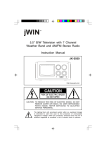
Juke Box With CD/Radio Instruction Manual JK-333 http://www.jwin.com CAUTION: TO REDUCE THE RISK OF ELECTRIC SHOCK, DO NOT REMOVE COVER (OR BACK). THERE ARE NO USER SERVICEABLE PARTS INSIDE. REFER SERVICING TO QUALIFIED SERVICE PERSONNEL. The lighting flash with arrowhead symbol within an equilateral triangle is intended to alert the user to the presence of uninsulated dangerous voltage within the product's enclosure that may be of sufficient magnitude to constitute a risk of electric shock to persons. The exclamation point within an equilateral triangle is intended to alert the user to the presence of important operating and maintenance (servicing) instructions in the literature accompanying the appliance. WARNING: TO REDUCE THE RISK OF FIRE OR ELECTRIC SHOCK. DO NOT EXPOSE THIS APPLIANCE TO RAIN OR MOISTURE. PORTABLE CART WARNING DO NOT REMOVE THIS TAG (MARKING) The words WARNING. MOVE WITH CARE. THIS CART/APPLIANCE COMBINATION SHOULD NOT BE MOVED BY CHILDREN WITHOUT PROPER GUIDANCE FROM AN ADULT OR An appliance and cart combination should be moved with care. Quick stops, excessive force, and uneven surfaces may cause the appliance and cart combination to overturn. IMPORTANT SAFETY INSTRUCTIONS CAUTION Electrical energy can perform many useful functions. This unit has been engineered and manufactured to assure your personal safety. Improper use can result in potential electrical shock or fire hazards. In order not to defeat the safeguards, observe the following basic rules for its installation, use and servicing. 1. Read Instructions All the safety and operating instructions should be read before the appliance is operated. 2. Retain Instructions The safety and operating instructions should be retained for future reference. 3. Heed Warnings All warnings on the appliance and in the operating instructions should be adhered to. 4. Follow Instructions All operating and use instructions should be followed. 5. Water and Moisture The appliance should not be used near water for example, near a bathtub, washbowl, kitchen sink, laundry tub, in a wet basement, or near a swimming pool, and the like. 6. Carts and Stands The appliance should be used only with a cart or stand that is recomended by the manufacturer. 1 6A. An appliance and cart combination should be moved with care. Quick stops, excessive force, and uneven surfaces may cause the appliance and cart combination to overturn. 7. Wall or Ceiling Mounting The appliance should be mounted to a wall or ceiling only as recommended by the manufacturer. 8. Ventilation The appliance should be situated so that its location or position does not interfere with its proper ventilation. For example, the appliance should not be situated on a bed, sofa, rug, or similar surface that may block the ventilation openings or placed in a built-in installation, such as a bookcase or cabinet that may impede the flow of air through the ventilation openings. 9. Heat The appliance should be situated away from heat sources such as radiators, heat registers, stoves, or other appliances (including amplifiers) that produce heat. 10. Power Sources The appliance should be connected to a power supply of the type described in the operating instructions or as marked on the appliance. 11. Grounding or Polarization Observe the precautions that should be taken so that the grounding or polarization protective features of an appliance are not defeated. 12. Power Cord Protection Power supply cords should be routed so that they are not likely to be walked on or pinched by items placed upon or against them, paying particular attention to cords at plugs, convenience receptacles, and the point where they exit from the appliance. 13. Protective Attachment Plug The appliance is equipped with an attactment plug that has overload protection. This is a safety feature. If replacement of the plug is required, be sure the service technician uses a replacement plug specified by the manufacturer that has the same overload protection as the original plug. 14A. Cleaning The appliance should be cleaned only as recommended by the manufacturer. 14B. Do not use liquid cleaners or aerosol cleaners. Use a damp cloth for cleaning. 15. Power Lines An outdoor antenna should be located away from power lines. 16. Outdoor Antenna Grounding If an outside antenna is connected to the receiver, be sure the antenna system is grounded so as to provide some protection against voltage surges and built up static charges. Section 801 of the National Electrical Code. ANSI/NFPA NO. 70-1984, provides information with respect to proper grounding of the mast and supporting structure, grounding of the lead-in wire to an antenna discharge unit, size of grounding electrodes, and requirements for the grounding electrode. See Figure 73.1. 17. Nonuse Periods The power cord of the appliance should be unplugged from the outlet when left unused for a long period of time. 2 18. Object and Liquid Entry Care should be taken so that objects do not fall and liquids are not spilled into the unit through openings. 19. Damage Requiring Service The appliance should be serviced by qualified service personnel when: A. The power supply cord or the plug has been damaged; or B. Objects have fallen, or liquid has been spilled into the appliance; or C. The appliance has been exposed to rain; or D. The appliance does not appear to operate normally or exhibits a marked change in performance; or E. The appliance has been dropped, or damaged. 20. Servicing The user should not attempt to service the appliance beyond instructions given in the operating instructions. All other servicing should be referred to qualified service personnel. POWER LINES SERVICE ENTRANCE CONDUCTORS GROUND CLAMPS STANDOFF INSULATORS b MAST SERVICE ENTRANCE EQUIPMENT ANTENNA LEAD IN WIRE GROUND WIRE GROUND CLAMPS ANTENNA DISCHARGE UNIT c TO EXTERNAL ANTENNA TERMINALS OF PRODUCT GROUND WIRE a. a GROUND CLAMPS a. a POWER SERVICE GROUNDING ELECTRODE SYSTEM (e.g. ntenor water pipe) BONDING JUMPER OPTIONAL ANTENNA GROUNDING ELECTRODE DRI/ENG FEET (2.44 m) INTO THE EARTH IF REQUIRED BY LOCAL CODES SEE NEC SECTION 810-21 (1) c FIGURE 73.1 EXAMPLE OF ANTENNA GROUNDING AS PER NATIONAL ELECTRICAL CODE INSTRUCTIONS CONTAINED IN ARTICLE 810RADIO AND TELEVISION EQUIPMENT a. Use No. 10 AWG (5.3 mm2) copper, No. 8 AWG (8.4 mm2) aluminium, No. 17 AWG (1.0 mm2) copper-clad steel or bronze wire, or larger, as a ground wire. b. Secure antenna lead-in and ground wire to house with stand-off insulators spaced from 4 - 6 feet (1.22 - 1.83 m) apart. c. Mount antenna discharge unit as close as possible to where lead-in enters house. d. Use jumper wire not smaller than No. 6 AWG (13.3 m 2) copper, or the equivalent when a separate antenna-grounding electrode is used. See NEC Section 810 - 21 (i). 3 LOCATION OF PARTS 2 3 1 12 11 15 16 13 14 19 18 17 4 6 5 7 8 9 10 1. 2. 3. 4. 5. 6. 7. 8. 9. 10. 11. 12. 13. 14. 15. 16. 17. 18. 19. Dial Display Door Dial Display Tuning Knob Speaker CD Door AM/FM Band Switch Function Switch Volume Control FM Antenna Power Plug 4 Fast Forward Button Power Indicator FM Stereo Indicator Stop Button Fast Reverse Button Repeat Button Play/Pause Button Program Button Program Indicator POWER SOURCE Unwind the AC power cord at the back of the unit and connect it to a power outlet. RADIO OPERATION 1. Switch the unit ON by turning the FUNCTION switch to the RADIO position. 2. Adjust the volume by turning the VOLUME control. 3. Select the desired waveband by adjusting the BAND selector to either the AM or FM position. 4. Open the DIAL DISPLAY DOOR. Select the desired station on the DIAL DISPLAY by rotating the TUNING KNOB. 5. Switch the unit OFF by turning the FUNCTION switch to the OFF position. ANTENNA For FM operation, the unit is provided with an antenna wire. Move the wire until the reception is clear with no interference. Do not connect external FM antenna to an outside antenna. This device has a built-in Am antenna, rotate the unit for best Am reception. CD OPERATION PLAYBACK 1. Rotate the FUNCTION switch to CD position. 2. Press the Open Symbol " " on the door to open the disc door. Place a disc in the tray with the labeled side facing out. 3. Close the door, the display will show "_ _" for a few seconds, then the total number of tracks on the disc will be displayed. 4. Press the PLAY/PAUSE BUTTON to start playback. 5. Adjust the VOLUME CONTROL as desired. 6. To stop playback temporarily, press the PLAY/PAUSE BUTTON. The play mode indicator will flash. Press the PLAY/PAUSE BUTTON again to resume playback. 7. To stop playback, press the STOP BUTTON and the play mode indicator will go off. FAST FORWARD AND FAST REVERSE 1. Press the FAST FORWARD or FAST REVERSE BUTTON to select a desired track. 2. Press the PLAY/PAUSE BUTTON to start playback of the selected track. SEARCH FORWARD AND REVERSE DURING PLAYBACK 1. Press the FAST FORWARD or FAST REVERSE BUTTON and keep it pressed to search forward or backward for the desired point on the track. 2. Release the button at the desired point, playback will resume automatically. REPEAT PLAYBACK 1. To select the single track repeat function, choose the track that you want to repeat, then press PLAY/PAUSE BUTTON to play the track. Press the REPEAT BUTTON once, to activate the single track repeat and the repeat indicator will flash. 2. To select the all tracks repeat function. Press the PLAY/PAUSE BUTTON to start the track. Press the REPEAT BUTTON twice, to activate the all tracks repeat function and the indicator will remain on. 3. To erase the repeat function, press again the REPEAT BUTTON until the indicator turns off. 5 PROGRAMMED PLAYBACK 1. In stop mode, press the PROGRAM BUTTON "0" (flashing) wil show on the display and the program indicator will flash. 2. Press the FAST FORWARD or REVERSE BUTTON to make track selection. 3. Press the PROG BUTTON again to store the selected track number. 4. Repeat steps 2 and 3 above to program other tracks. 5. Press the PLAY/PAUSE BUTTON to start programmed playback and the program indicator will on. 6. To erase the programmed, press the PROG BUTTON and press the STOP BUTTON once or open the CD door. NOTE: Maximum of 19 tracks can be programmed to play in any order. SPECIFICATIONS: Power Source Speaker Impedance Output Power : : : 120V/60Hz 3½" 8 ohm 1.5W x 2 R.M.S. CD Frequency Response Sampling Frequency : : 100 - 16,000 Hz 44.1 KHz Tape Frequency Response Tape Speed : : 100 - 8,000 Hz 4.75 cm/sec. TROUBLE SHOOTING GUIDE The unit does not operate Is the AC power cord connected to a power outlet and fully inserted? Is the unit turned on? Rotate the FUNCTION switch from the OFF position to turn on the unit. No radio Is the FUNCTION switch in the correct position? Turn FUNCTION switch to Radio. Adjust the VOLUME knob. Rotate the TUNING knob to find a radio station. 6 MUST RETURN BY MAIL IMPORTANT! PLEASE READ: In order to validate this warranty, fill out this portion in its entirety and return to jWIN within 10 DAYS of purchase. Please print clearly. jWIN will not be liable if we are unable to process your warranty due to illegibility, failure to complete the form properly, or failure to return the form as specified. Model Number: Serial No. Owner's Name: Date of Purchase: Address: City: State: Zip Code: Store Name: Store Address: City: State: Zip Code: Cut along this line 1 YEAR PARTS / 90 DAYS LABOR LIMITED WARRANTY This warranty applies to customers in the U.S. (mainland) only. Please refer to our website for international jWIN Electronics defects effective in Corp. materials from the and date (jWIN) warrants workmanship of original serivice information. this under purchase. product normal jWIN to use the during agrees, at our original the purchaser period option, to ONLY, specified replace or to under repair be this free from warranty your product with a new or reconditioned product without any charge. This warranty, of course, does not cover cosmetic damage, cabinets, cabinet parts, knobs, stylus, antennas, handles, batteries, plugs, line cords, tapes and accessories, or damage due to line power surges, connection to improper voltage supply or settings, misuse, mishandling, acts of God, or attempted repair by an unauthorized service agent, or any product whose serial number has been removed, altered, replaced, defaced, or rendered illegible. A minimum $25.00 fee will be charged for any repair service beyond 90 Days from the date of original purchase. To obtain factory service, the original purchaser MUST present proof of purchase and send the unit pre-paid to the address below. Also, a $10.00 money order made payable to jWIN Electronics Corp. must be included to cover return shipping charges. jWIN Customer Service, 51-41 59th Place, Woodside, N.Y.11377 There are no express warranties except as listed above. REPAIR OR REPLACEMENT AS PROVIDED UNDER THIS WARRANTY IS THE EXCLUSIVE REMEDY OF THE CONSUMER. jWIN SHALL NOT BE LIABLE FOR ANY INCIDENTAL WARRANTY IMPLIED ON OR THIS WARRANTY PRODUCT IS CONSEQUENTIAL PRODUCT. OF LIMITED IN EXCEPT DAMAGES TO MERCHANTABILITY DURATION TO THE OR THE FOR BREACH EXTENT FITNESS DURATION OF ANY PROHIBITED FOR OF A BY EXPRESS PARTICULAR THIS OR APPLICABLE WARRANTY. PURPOSE Some IMPLIED LAW, ON states ANY THIS do not allow the exclusion or limitation of incidental or consequential damages, or limitations on how long an implied warranty lasts, so the above exclusions or limitations may not apply to you. This warranty gives you specific legal rights and you may also have other rights which vary from state to state. jWIN Electronics Corp. 51-41, 59th Place Woodside, N.Y. 11377 Attn: Customer Service