1
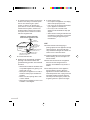
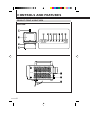
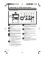
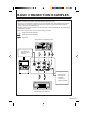
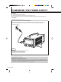
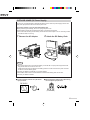
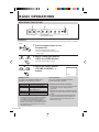
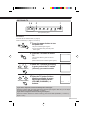
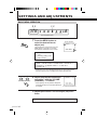
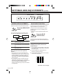
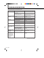
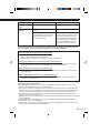
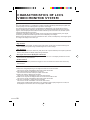
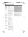
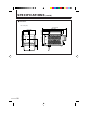
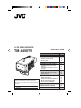
LCCS VIDEO MONITOR
TM-L450TU
INSTRUCTIONS
Contents
–
+
VOLUM
E(CHAN
NEL)
TV
VIDEO
A
VIDEO
B
MEN
U
BLUE
CHECK
SIZE
SELECT
POW
ER
For Customer Use:
Enter below the Serial No. which is located on the
bottom of the cabinet. Retain this information for future
reference.
Model No.
:
Serial No.
:
TM-L450TU
IMPORTANT SAFETY PRECAUTIONS
CONTROLS AND FEATURES
FRONT & RIGHT VIEW
REAR VIEW
BASIC CONNECTION EXAMPLES
PREPARING POWER SUPPLY
INDOOR USAGE (AC Power
Supply)
OUTDOOR USAGE (DC Power
Supply)
BASIC OPERATIONS
MONITORING THE PICTURE
WATCHING TV
SETTINGS AND ADJUSTMENTS
BASIC MENU OPERATION
MENU CONTENTS
SCREEN SIZE ADJUSTMENTS
BLUE CHECK FUNCTION
SETTING TV CHANNELS
TROUBLESHOOTING
CHARACTERISTICS OF LCCS
VIDEO MONITOR SYSTEM
SPECIFICATIONS
Page
2
6
6
8
9
10
10
11
12
12
13
14
14
15
16
16
17
18
20
21
Thank you for purchasing this JVC LCCS video monitor.
Before using, read and follow all instructions carefully to take full advantage of the monitor’s capabilities.
Retain these instructions for future reference.
* LCCS = Liquid Crystal Color Shutter
IMPORTANT SAFETY
PRECAUTIONS
CAUTION
RISK OF ELECTRIC SHOCK
DO NOT OPEN
CAUTION: To reduce the risk of electric shock.
do not remove cover (or back).
No user serviceable parts inside.
Refer servicing to qualified service personnel.
The lightning flash with arrowhead symbol, within an equilateral
triangle, is intended to alert the user to the presence of uninsulated
"dangerous voltage" within the product's enclosure that may be of
sufficient magnitude to constitute a risk of electric shock to persons.
The exclamation point within an equilateral triangle is intended to
alert the user to the presence of important operating and
maintenance (servicing) instructions in the literature accompanying
the appliance.
WARNING:
TO PREVENT FIRE OR SHOCK HAZARDS,
DO NOT EXPOSE THIS APPLIANCE TO
RAIN OR MOISTURE.
CAUTION:
TO INSURE PERSONAL SAFETY,
OBSERVE THE FOLLOWING RULES
REGARDING THE USE OF THIS UNIT.
1. Operate only from the power source
specified on the unit.
2. Avoid damaging the AC plug and power
cord.
2
3. Avoid improper installation and never
position the unit where good ventilation is
unattainable.
4. Do not allow objects or liquid into the
cabinet openings.
5. In the event of trouble, unplug the unit and
call a service technician. Do not attempt to
repair it yourself or remove the cover.
Changes or modifications not approved by
JVC could void the warranty.
* When you don’t use this Appliance for a
long period of time, be sure to disconnect
both the power plug from the AC outlet and
antenna for your safety.
IMPORTANT SAFEGUARDS
CAUTION:
Please read and retain for your safety.
Electrical energy can perform many useful
functions. This Appliance has been engineered
and manufactured to assure your personal
safety. But improper use can result in potential
electrical shock or fire hazards. In order not to
defeat the safeguards incorporated in this
Appliance, observe the following basic rules for
its installation, use and servicing.
And also follow all warnings and instructions
marked on your Appliance.
INSTALLATION
1 Your Appliance is equipped with a
grounding-type AC line plug (three-blade
type), a plug having a third (grounding)
pin.
(GROUNDING-TYPE)
This plug will only fit into a grounding-type
power outlet. This is a safety feature.
Should you be unable to insert the plug
into the outlet, contact your electrician to
replace your outlet. Do not defeat the
safety purpose of the grounding-type plug.
3 Overloaded AC outlets and extension
cords are dangerous, and so are frayed
power cords and broken plugs. They may
result in a shock or fire hazard. Call your
service technician for replacement.
4 Do not allow anything to rest on or roll
over the power cord, and do not place the
Appliance where power cord is subject to
traffic or abuse. This may result in a shock
or fire hazard.
5 Do not use this Appliance near water —
for example, near a bathtub, washbowl,
kitchen sink, or laundry tub, in a wet
basement, or near swimming pool, etc.
6 If an outside antenna is connected to the
Appliance, be sure the antenna system is
grounded so as to provide some protection
against voltage surges and built-up static
charges. Section 810 of the National
Electrical Code provides information with
respect to proper grounding of the mast
and supporting structure, grounding of the
lead-in wire to an antenna discharge unit,
size of grounding conductors, location of
antenna discharge unit, connection
requirements for the grounding electrode.
2 Operate the Appliance only from a power
source as indicated on the Appliance or
refer to the operating instructions for this
information. If you are not sure of the type
of power supply to your home, consult
your Appliance dealer or local power
company. For battery operation, refer to
the operating instructions.
(continued on the next page)
3
7 An outside antenna system should not be
located in the vicinity of overhead power
lines or other electric light or power
circuits, or where it can fall into such
power lines or circuits. When installing an
outside antenna system, extreme care
should be taken to keep from touching
such power lines or circuits as contact
with them might be fatal.
EXAMPLE OF ANTENNA GROUNDING
AS PER NATIONAL ELECTRICAL CODE
9 To avoid personal injury:
– Do not place an Appliance on a sloping
shelf unless properly secured.
– Use only a cart or stand recommended
by the Appliance manufacturer.
– Do not try to roll a cart with small
casters across thresholds or deep pile
carpets.
– Wall or shelf mounting should follow the
manufacturer’s instructions, and should
use a mounting kit approved by the
manufacturer.
ANTENNA
LEAD IN WIRE
USE
GROUND CLAMP
ELECTRIC SERVICE
EQUIPMENT
ANTENNA
DISCHARGE UNIT
(NEC SECTION
810-20)
GROUNDING CONDUCTORS
(NEC SECTION 810-21)
GROUND CLAMPS
POWER SERVICE GROUNDING ELECTRODE SYSTEM
(NEC ARTICLE 250, PART H)
NEC – NATIONAL ELECTRICAL CODE
8 Appliances are provided with ventilation
openings in the cabinet to allow heat
generated during operation to be released.
Therefore:
– Never block the bottom ventilation slots
of a portable Appliance by placing it on
a bed, sofa, rug, etc.
– Never place an Appliance in a “built-in”
enclosure unless proper ventilation is
provided.
– Never cover the openings with a cloth
or other material.
– Never place the Appliance near or over
a radiator or heat register.
4
10 Caution children about dropping or
pushing objects into the Appliance through
cabinet openings. Some internal parts
carry hazardous voltages and contact can
result in a fire or electrical shock.
11 Unplug the Appliance from the wall outlet
before cleaning. Do not use liquid or an
aerosol cleaner.
12 Never add accessories to an Appliance
that has not been designed for this
purpose. Such additions may result in a
hazard.
13 For added protection of the Appliance
during a lightning storm or when the
Appliance is to be left unattended for an
extended period of time, unplug it from the
wall outlet and disconnect the antenna.
This will prevent damage to product due
to lightning storms or power line surges.
14 An Appliance and cart combination should
be moved with care. Quick stops, excessive
force, and uneven surfaces may cause the
Appliance and cart combination to overturn.
16 Do not attempt to service this Appliance
yourself as opening or removing covers
may expose you to dangerous voltage or
other hazards. Refer all servicing to
qualified service personnel.
17 When replacement parts are required,
have the service technician verify in
writing that the replacement parts he uses
have the same safety characteristics as
the original parts. Use of manufacturer’s
specified replacement parts can prevent
fire, shock, or other hazards.
SERVICE
15 Unplug this Appliance from the wall outlet
and refer servicing to qualified service
personnel under the following conditions:
A. When the power cord or plug is
damaged or frayed.
B. If liquid has been spilled into the
Appliance.
C.If the Appliance has been exposed to
rain or water.
D.If the Appliance does not operate
normally by following the operating
instructions. Adjust only those controls
that are covered in the operating
instructions as improper adjustment of
other controls may result in damage
and will often require extensive work by
a qualified technician to restore the
Appliance to normal operation.
E. If the Appliance has been dropped or
damaged in any way.
F. When the Appliance exhibits a distinct
change in performance — this indicates
a need for service.
18 Upon completion of any service or repairs
to this Appliance, please ask the service
technician to perform the safety check
described in the manufacturer’s service
literature.
19 When an Appliance reaches the end of its
useful life, improper disposal could result
in a picture tube implosion. Ask a qualified
service technician to dispose of the
Appliance.
20 Note to CATV system installer.
This reminder is provided to call the CATV
system installer’s attention to Article 82040 of the NEC that provides guidelines for
proper grounding and, in particular,
specifies that the cable ground shall be
connected to the grounding system of the
building, as close to the point of cable
entry as practical.
SCREEN BURN
● Try to avoid displaying still images or extremely bright images on the screen for an extended
period of time. If left on screen for too long the image will be permanently etched onto the
CRT — a phenomenon known as “screen burn”. Screen burn is not a problem when
displaying moving pictures during video playback.
5
CONTROLS AND FEATURES
PRODUCT: FRONT & RIGHT VIEW
FRONT VIEW
–
–
VOLUME(CHANNEL)
+
VOLUME(CHANNEL)
+
TV
VIDEO A
VIDEO B
MENU
BLUE
CHECK
SIZE
SELECT
TV
VIDEO A
POWER
RIGHT VIEW
EAR
PHONE
6
VIDEO B
MENU
BLUE
CHECK
SIZE
SELECT
POWER
FRONT VIEW
1 Carrying Handle
Used to carry the monitor.
Can be removed when the monitor is mounted
in a rack.
2 Screen
A removable shield protecting the liquid crystal
shutter is provided.
3 Feet
Can be removed when the monitor is mounted
in a rack.
4 Stand
The monitor will be tilted about 18° when the
stand is pulled out.
Can be removed when the monitor is mounted
in a rack.
* DO NOT push down on the monitor from
above or place heavy objects on it when the
stand is pulled out.
5 VOLUME (CHANNEL) –/+ Buttons
● Usually used as VOLUME (CHANNEL) –/+
buttons to adjust the volume.
● For about 8 seconds after the TV button is
pressed (while the TV button is blinking in
green), they act as VOLUME (CHANNEL)
–/+ buttons for changing TV channels.
6 TV Button
Press this button to watch TV.
The button blinks in green when it is pressed.
While it is blinking, you can change channels
with the VOLUME (CHANNEL) –/+ buttons.
If you want to adjust the volume while the TV
button is blinking, press the TV button again so
that the button lights in green, then adjust the
volume with the VOLUME (CHANNEL) –/+
buttons.
The TV button lights in green when TV is
selected.
9 MENU Button
Press this button to access the menu for
performing settings and adjustments on the
monitor.
The selected item displayed on the menu
changes each time this button is pressed.
10 BLUE CHECK Button
Press this button to use the blue check
function.
The blue check function helps make the
CHROMA and PHASE settings more accurate.
11 SIZE SELECT Button
Press this button to change the screen size.
The screen size changes each time this button
is pressed.
12 POWER Switch/Indicator
Press this switch to turn the power ON or OFF.
The POWER indicator lights in green when the
power is ON.
RIGHT VIEW
13 Earphone Terminal
Stereo minijack output terminal.
(Actual output is monaural.)
14 Built-in Speaker
A built-in speaker is located in the right panel
when the monitor is viewed from the front.
(When earphones are connected to the
earphone terminal, no sound is output from the
speaker.)
15 Intake Fan
DO NOT cover the intake fan or ventilation slot
as this could cause the monitor to overheat,
resulting in a fire or malfunction.
7 VIDEO A Button
Press this button to select the video signal input
to the VIDEO A terminal and the audio signal
input to the AUDIO IN A terminal.
The button lights in green when VIDEO A is
selected.
8 VIDEO B Button
Press this button to select the video signal input
to the VIDEO B terminal and the audio signal
input to the AUDIO IN B terminal.
The button lights in green when VIDEO B is
selected.
7
CONTROLS AND FEATURES
(cont’d)
PRODUCT: REAR VIEW
AC
IN
75
VHF/UHF
DC IN 12V
IN
IN
A
75
VHF/UHF
DC IN 12V
IN
IN
OUT
OUT
ANT. IN
A
ANT. IN
VIDEO A
VIDEO B
DC IN 19V
B
OUT
VIDEO A
1 AC IN (AC Power Input) Terminal
Power input terminal.
Connect the provided power cord to the
terminal.
2 AC Adapter
Can be removed when a commercial DC power
supply (DC 12 V) is used.
3 DC IN 12 V (DC Power Input) Terminal
Connect a commercial DC power supply.
(Consult your dealer for usable DC power
supplies.)
4 75 Ω VHF/UHF (TV Antenna) Terminal
Connect the TV antenna cable to watch TV.
5 VIDEO A Terminals
BNC video signal input (IN) and output (OUT)
terminals. The output terminal is bridgeconnected (auto termination).
IN : Connect to the composite video signal
output terminal of a video camera, etc.
OUT : Connect to the composite video signal
input terminal of a VCR, etc.
6 VIDEO B Terminals
BNC video signal input (IN) and output (OUT)
terminals. The output terminal is bridgeconnected (auto termination).
IN : Connect to the composite video signal
output terminal of a video camera, etc.
OUT : Connect to the composite video signal
input terminal of a VCR, etc.
8
OUT
(AC ADAPTER)
DC IN 19V
B
(AC ADAPTER)
AUDIO IN REMOTE IN
VIDEO B
AUDIO IN REMOTE IN
7 AUDIO IN A Terminal
RCA-pin monaural audio signal input terminal.
Connect it to the audio signal output terminal of
the video camera, etc. connected to the VIDEO
A input (IN) terminal.
8 DC IN 19 V Terminal (Exclusively for
Provided AC Adapter)
Connect the provided AC adapter to this
terminal.
* DO NOT use any AC adapter other than the
one provided.
9 REMOTE IN (Remote Control Input)
Terminal
Mini-jack input terminal.
A wired remote control can be connected to this
terminal.
(Consult your dealer for details.)
10 AUDIO IN B Terminal
RCA-pin monaural audio signal input terminal.
Connect it to the audio signal output terminal of
the video camera, etc. connected to the VIDEO
B input (IN) terminal.
BASIC CONNECTION EXAMPLES
● Before connecting your system, make sure that all units are turned off.
● If you are not connecting any equipment to one of the bridged video output (VIDEO OUT) terminals,
be sure NOT to connect any cables to the terminal as this will cause the terminating resistance
switch to open (auto terminate function).
● DO NOT connect a piece of equipment to the same pair of video input (VIDEO IN) and video output
(VIDEO OUT) terminals.
● Also refer to the instructions of the equipment being connected.
: VIDEO A Connection Example
: VIDEO B Connection Example
: Signal Flow
Video Camera or Other Equipment
Connect the TV
antenna cable to
watch TV.
75
VHF/UHF
AC IN
IN
IN
A
75
VHF/UHF
DC IN 12V
IN
IN
OUT
OUT
ANT. IN
A
ANT. IN
VIDEO A
VIDEO B
DC IN 19V
B
OUT
OUT
(AC ADAPTER)
B
AUDIO IN REMOTE IN
VIDEO A
VIDEO B
AUDIO IN REMOTE IN
A wired remote
control can be
connected.
* Consult your
dealer for details.
Video Equipment for Recording
9
PREPARING THE POWER SUPPLY
Precautions
Use one of the following power supplies:
● AC power supply (120 V AC, 60 Hz): Use the provided power cord.
● DC power supply (12 V DC): Use any brand of external DC battery pack (commercial) or other DC
power supply.
INDOOR USAGE (AC Power Supply)
Connect the provided power cord to the AC IN (AC power input) terminal and an AC outlet.
● When AC power supply is used, the power from the DC IN 12 V (DC power input) terminal is
automatically cut off.
DC IN
12V
75
VHF/UHF
IN
IN
ANT. IN
A
OUT
OUT
VIDEO
A
B
VIDEO
B
AUDIO IN
DC IN 19V
(AC ADA
PTER)
REMOTE
IN
Note:
● Do not use any AC adapter other than the one
provided (model: ADP-50VB REV. D),
otherwise it may cause a malfunction.
Using Outside North America
A different AC power cord will be required.
● The AC power cord provided with this monitor can only be used with AC 120 V, 50 Hz/60 Hz (North
America). To use this monitor outside North America, you will need to get a different AC power cord
that matches the voltage and/or power plug used in that country.
10
UPPLY
OUTDOOR USAGE (DC Power Supply)
Connect any commercial brand of external DC battery pack or other DC power supply to DC IN 12 V
(DC power input) terminal with the exclusive power cord.
Connection example: using an external DC battery pack
Before performing the following, be sure to unplug the power cord.
The DC battery pack fits into the attachment holes on the back of the monitor.
● The screw holes for fixing the DC battery are M4 size and have a depth of 12 mm. The fixing screws
must be less than 12 mm long.
1
Remove the AC Adapter.
2
Attach the DC Battery Pack.
DC IN 12V
75
VHF/UHF
IN
IN
ANT. IN
A
OUT
OUT
DC IN
12V
VIDEO
75
VHF/UHF
IN
IN
ANT. IN
B
A
VIDEO
B
AUDIO IN
DC IN
19V
(AC ADAPT
ER)
REMOTE
IN
A
OUT
OUT
VIDEO
B
A
VIDEO
B
AUDIO IN
DC IN
19V
(AC ADAPT
ER)
REMOTE
IN
Notes:
● Do not leave the monitor connected to a battery via the DC IN 12 V (DC power input) terminal for
long periods when the monitor is not in use.
A slight electrical current is passed to the battery protection circuit even when the power is turned
off, which consumes battery power.
● Consult your dealer for usable DC 12 V power supplies.
● Anton Bauer, PAG or other commercial brand of external DC battery pack can be used.
● Consult your dealer for details.
䡵 Electrical Polarity of DC IN 12 V (DC Power
Input) Terminal
䡵 Electrical Polarity of DC IN 19 V (Exclusively
for AC Adapter Input) Terminal
DC IN 12V
DC IN 19V
(AC ADAPTER)
11
BASIC OPERATIONS
MONITORING THE PICTURE
3
–
2
1
+
VOLUME(CHANNEL)
TV
VIDEO A
VIDEO B
MENU
BLUE
CHECK
SIZE
SELECT
POWER
Front operation panel
Precautions
● Connect video components properly to the connection terminals on the rear of the monitor. (墌 pages 8
and 9)
1
The power indicator lights in green.
● To turn the power OFF, press the power
button again.
POWER
2
VIDEO A
Press the power button to turn
the power ON.
VIDEO B
Select a video input with the
VIDEO A or VIDEO B button.
The button pressed lights in green.
–
+
3
VOLUME(CHANNEL)
Adjust the volume with the
VOLUME (CHANNEL) –/+
buttons.
Screen indication
VOLUME
POWER Indicator
The status of the POWER indicator varies
depending on the following conditions:
Unlit
Lights in green
Lights in orange
*1
Lights in red *1
Blinks in green
Power OFF
Power ON, usual operation
Low voltage from DC power
supply (battery, etc.)
Battery protection circuit active
Power save function active
*1: The color of the POWER indicator does not
show the exact status of the battery. Depending
on the battery type, the power may be cut off
even before the POWER indicator lights in
orange/red. This is due to characteristics of the
battery or the operation of the battery protection
circuit, and is not a malfunction. If this occurs,
recharge the battery.
12
13
Screen Indication
The screen indication disappears about 8
seconds after button operation.
Unsuitable Environments for Viewing
● Watching the monitor in a room that is too dark
can damage your eyes. Keep the room
properly lit.
Watching the monitor for long periods can also
damage your eyes. Be sure to take occasional
breaks.
● The picture may appear distorted depending
on the environment around the monitor. If it
does, DO NOT use the monitor as it could
damage your eyes.
WATCHING TV
3, 4
–
2
1
+
VOLUME(CHANNEL)
TV
VIDEO A
VIDEO B
MENU
BLUE
CHECK
SIZE
SELECT
POWER
Front operation panel
Precautions
● Connect the TV antenna cable. (墌 page 9)
● Set TV channels. (墌 pages 14, 15 and 17)
1
The power indicator lights in green.
● To turn the power OFF, press the power
button again.
POWER
2
+
3
While the TV button is blinking
in green, select the TV station
(channel) you want to watch.
4
After the TV button finishes
blinking and lights in green,
adjust the volume with the
VOLUME (CHANNEL) –/+
buttons.
VOLUME(CHANNEL)
–
Press the TV button to select
TV.
Screen indication
TV 10
The TV button blinks in green for about 8
seconds.
(After 8 seconds, the TV button lights in green.)
TV
–
Press the power button to turn
the power ON.
+
VOLUME(CHANNEL)
TV 8
VOLUME
12
If you want to adjust the volume immediately after selecting TV:
Press the TV button again. The button stop blinking and then lights in green. After that, you can adjust
the volume with the VOLUME (CHANNEL) –/+ buttons.
If you want to change the TV channel during TV reception:
Press the TV button. While the TV button is blinking, press the VOLUME (CHANNEL) –/+ buttons. (+:
higher/–: lower)
13
SETTINGS AND ADJUSTMENTS
BASIC MENU OPERATION
2, 3
–
1, 3
+
VOLUME(CHANNEL)
TV
VIDEO A
VIDEO B
MENU
BLUE
CHECK
SIZE
SELECT
POWER
Front operation panel
1
MENU
Press the MENU button to
select the desired item to
adjust (set).
The selected item changes each time the
MENU button is pressed. The currently
selected item is displayed on the monitor.
Screen indication
CONTRAST :
+16
SELECT: MENU
ADJUST: VOLUME +/–
Screen Indications
1 Item
2 Adjusting (setting) value
3 Help indication
CONTRAST = BRIGHTNESS = SHARPNESS = CHROMA =
PHASE = COLOR SYSTEM = POWER SAVE = COLOR SW =
CH STATUS = CH SEARCH START = CH SKIP ON =
CH RESET ON = ……
* Some items may not be displayed depending on which input mode is
selected. Items that are not displayed cannot be adjusted (set).
–
+
2
VOLUME(CHANNEL)
Adjust (set) the item selected in
procedure 1 with the VOLUME
(CHANNEL) –/+ buttons.
* When adjusting, the help indicator disappears.
It is displayed again 2 seconds after adjustment
is complete.
3
CONTRAST:
+24
SELECT: MENU
ADJUST: VOLUME +/–
Ex. Adjusting CONTRAST
Repeat procedures 1 and 2 to adjust (set) more
items.
* Refer to MENU CONTENTS on the next page for the name of each item.
14
NTS
MENU CONTENTS
You can adjust (set) the following items on the
menu screen. Each adjusted (set) value is
automatically memorized.
The values inside [ ] are the factory presets.
1 CONTRAST (Picture Contrast)
Adjusts the picture contrast. Decreasing the
value lowers the contrast, and increasing the
value raises it.
Adjustable range: –30 to +30
[0]
2 BRIGHTNESS (Picture Brightness)
Adjusts the picture brightness.
Decreasing the value makes the picture darker,
and increasing the value makes it brighter.
Adjustable range: –30 to +30
[0]
3 SHARPNESS (Picture Sharpness)
Adjusts the picture sharpness.
Decreasing the value makes the picture softer,
and increasing the value makes it more sharp.
Adjustable range: –30 to +30
[0]
4 CHROMA (Picture Chroma)
Adjusts the picture chroma.
Decreasing the value makes the picture lighter,
and increasing the value makes it deeper.
Adjustable range: –30 to +30
[0]
5 PHASE (Picture Phase)
Adjusts the picture phase.
Decreasing the value makes the picture more
reddish, and increasing the value makes it more
greenish.
Adjustable range: –30 to +30
[0]
* PHASE can be adjusted only with NTSC
video signals.
* PHASE is not displayed when PAL is
selected.
6 COLOR SYSTEM (Color System)
Displays the color system (NTSC or PAL) used
by the video equipment.
* COLOR SYSTEM is not displayed when TV
is selected.
7 POWER SAVE (Power Save)
With the power save function set to ON (active),
the monitor automatically enters standby mode
when no video signal is input. When the power
save function is active, the POWER indicator
blinks in green. When a video signal is input, the
power save function becomes inactive and the
monitor is restored to normal operation.
Pressing any buttons on the front operation
panel also sets the power save function to
inactive.
[OFF]
* The power save function becomes active
when no video signal is input for over 30
seconds.
8 COLOR SW
Turns the picture into black and white for
checking the white balance.
[ON]
The following items are displayed only when TV
is selected:
9 CH STATUS (Channel Status)
With CH STATUS set to OFF (inactive), the TV
channel is not displayed when it is selected.
[ON]
0 CH SEARCH START (Initiate Channel Search)
The monitor automatically searches for
broadcast stations (VHF/UHF) it can receive and
memorizes them.
(Also refer to SETTING TV CHANNELS on page
17.)
* The monitor memorizes channels in
ascending order.
* When you move the monitor into an area
that receives different channels, perform
CH SEARCH START again.
! CH SKIP ON (Channel Skip ON)
Deletes a channel set in CH SEARCH 0. Select
the channel to be deleted and perform CH SKIP
ON.
@ CH RESET ON (Channel Reset ON)
Resets all TV channels set in 0 CH SEARCH
START to their factory presets. After performing
channel reset, all TV channels (VHF: 2 – 13 /
UHF: 14 – 69) can be tuned.
15
SETTINGS AND ADJUSTMENTS
BLUE CHECK
+
VIDEO B
SCREEN SIZE ADJUSTMENTS
Adjust the screen size to get the desired picture.
Press the SIZE SELECT
button.
The screen size changes in the following order
each time the SIZE SELECT button is pressed.
OVER
UNDER
16:9
OVER
suitable for monitoring a picture with a
normal aspect ratio of 4:3
UNDER can monitor an entire picture with a
normal aspect ratio of 4:3 by reducing its
size
16:9
suitable for monitoring a picture with an
aspect ratio of 16:9
When using the screen mode adjustment
function:
● This monitor has a screen mode adjustment
(SIZE SELECT) function. When a screen mode
is selected that does not match the aspect ratio
of the TV program or other video source you
want to watch, the picture may appear different
from the original.
● If you place this monitor in a public space (e.g.
coffee shop, hotel lobby, etc.) for commercial
purposes or for public exhibition, and if you use a
screen mode adjustment (SIZE SELECT)
function on the video image, it may be a violation
of copyright law.
MENU
BLUE
CHECK
SIZE
SELECT
POWER
BLUE CHECK FUNCTION
The blue check function cuts the red and green
signal and displays only the blue signal.
The blue check function enables you to adjust
CHROMA (picture chroma) or PHASE (picture
phase) easily.
* PHASE can only be adjusted with NTSC video
signals.
BLUE
CHECK
Press the BLUE
CHECK button.
The blue check function switches ON (active) or
OFF (inactive) each time the BLUE CHECK button
is pressed.
Adjusting CHROMA (picture chroma) or
PHASE (picture phase) with the blue
check function:
1 Input a standard color bar (NTSC or PAL) signal
to the VIDEO A IN or VIDEO B IN terminal at the
rear of the monitor.
2 Press the VIDEO A or VIDEO B button to
display the standard color bars.
3 Press the BLUE CHECK button to turn the blue
check function ON (active).
blue
VIDEO A
blue
TV
blue
VOLUME(CHANNEL)
SIZE
SELECT
SIZE SELECT
blue
–
(cont’d)
(continued on the next page)
16
S
(cont’d)
4 Adjust CHROMA (picture chroma) or PHASE
(picture phase).
When an NTSC color bar signal is input:
1 Adjust CHROMA (picture chroma) so that the
blue bars on the left and right side of the
screen have the same brightness.
2 Adjust PHASE so that the two blue bars at
the center of the screen have the same
brightness.
3 Repeat procedure 1 and 2 so that all four
blue bars on the screen have the same
brightness.
When a PAL color bar signal is input:
Adjust CHROMA (picture chroma) so that the
blue bars on the left and right side of the screen
have the same brightness.
* Refer to BASIC MENU OPERATION on
page 14 for the adjustment procedure.
5 After adjustment is complete, press the BLUE
CHECK button again to turn the blue check
function OFF (inactive).
SETTING TV CHANNELS
This monitor is factory-preset to tune all VHF (2 to
13) and UHF (14 to 69) TV channels.
● To perform the following, press the TV button to
select TV.
When you want to reset the memorized TV
channels, perform CH SEARCH START (initiate
channel search) from the menu screen (refer to
pages 14 and 15). The monitor automatically
searches for broadcasting stations (VHF/UHF) and
memorizes them.
You can also delete channels you do not want to
watch. Select the channel to be deleted and
perform CH SKIP ON (channel skip ON) from the
menu screen (refer to pages 14 and 15).
* Channels deleted by CH SKIP ON (channel skip
ON) cannot be tuned again. If you want to tune
them, perform CH RESET ON (channel reset ON)
from the menu screen to tune all VHF (2 to 13)
and UHF (14 to 69) TV channels.
* In areas where the radio wave reception weak,
searching for TV channels will not function well.
In this case, perform CH RESET ON (channel
reset ON) from the menu screen to tune all VHF
(2 to 13) and UHF (14 to 69) TV channels.
17
TROUBLESHOOTING
Before requesting repair, check the following points.
Problems
No power supply.
No picture with the
power on.
No sound.
Points to be checked
Measures (remedy)
Is the power plug loosened or
disconnected?
Firmly insert the power plug.
Is the battery charged properly? (when
a DC power supply is used)
Charge the battery or replace the
charged battery (refer to the battery
charger you are using).
Is the signal output from the connected
equipment?
Set the connected equipment
correctly.
Is the input signal selected correctly?
Select the correct input.
Is the video signal cable disconnected?
Connect the video signal cable firmly.
Is the audio signal output from the
connected equipment?
Set the connected equipment
correctly.
Is the volume set to minimum?
Adjust the volume properly.
Is the audio signal cable disconnected?
Connect the audio signal cable firmly.
Picture is shaking.
Is the monitor close to a motor,
transformer or other device generating
a strong magnetic field?
Move the monitor away from the
device until the picture stops shaking.
No colors, wrong
colors, or dark
picture.
Has COLOR SW been set to OFF?
Set COLOR SW to ON in the menu.
Has the picture control setting
(CONTRAST, BRIGHTNESS,
CHROMA or PHASE) been changed?
Adjust each setting to the standard
value [0].
Some parts of the
picture are
distorted.
Is the monitor close to a speaker or
magnet? Did you move a speaker or
magnet close to the monitor?
Keep speakers and magnets away
from the monitor.
There are black
parts on the top
and bottom of the
screen, and both
horizontal sides of
the picture is
indented.
Is the screen size set to 16:9?
Set the screen size to OVER or
UNDER.
(continued on the next page)
18
Problems
Points to be checked
Measures (remedy)
The screen size is
small.
Is the screen size set to UNDER?
Set the screen size to OVER.
There is no TV
reception.
Is an antenna connected to the
monitor?
Connect the TV antenna cable.
Was the monitor moved to an area that
receives different channels after CH
SEARCH START (initiate channel
search) was performed?
Perform CH SEARCH START each
time the monitor is moved to an area
that receives different channels so
that the monitor can memorize the
new broadcast stations. Otherwise,
perform CH RESET ON (channel
reset ON) to tune all TV channels.
There may not be a solution to the following problems, although adjusting the antenna or taking
measures against interfering equipment may improve the situation somewhat.
The screen appears snowy and noise is heard. (Snow)
● Is the antenna connected properly?
● Has the antenna cable been cut or loosened?
● Has the antenna orientation been changed or is the antenna broken?
The image is displayed two or three times on the monitor. (Ghosting)
● This may be caused by mountains or buildings. Also, if the broadcast antenna is located nearby,
the TV transmission the monitor receives directly from it may affect the picture.
Spots are displayed and noise is heard. (Interference)
● This may be caused by interfering radio waves generated by dryers, automobiles, motorcycles or
fluorescent lights.
Stripes are displayed and noise is heard. (Radio Interference)
● This may be caused by radio interference generated by radio stations, personal computers, AV
equipment or microwave ovens.
The following are not malfunctions:
● The monitor emits a strange sound when the room temperature changes suddenly. This is only a
problem if an abnormality appears on the screen as well.
● If two or more monitors are operated next to each other, their images may shake or be distorted. This
phenomenon is due to mutual interference; it is not a malfunction. Move the monitors away from each
other until the interference disappears or turn the power off on any monitor that is not being used.
● If a magnet or speaker is placed close to the monitor, the picture may shake. This is caused by the
magnetic effect and is not a malfunction.
● When the monitor is turned ON, the sound of a running motor may be heard. This is the cooling fan and
is not a malfunction.
● When playing back a video tape, the upper edge of the picture may be distorted. This is caused by
skew distortion and is not a malfunction.
● Vertical stripes may occur on a dark picture. This is caused by quantization noise (noise which occurs
when a picture is digitized) and is not a malfunction.
19
CHARACTERISTICS OF LCCS
VIDEO MONITOR SYSTEM
■ PRINCIPLE BEHIND LCCS VIDEO MONITOR OPERATION
The LCCS Video Monitor is a combination of a black-and-white cathode-ray tube and liquid crystal color
shutter (LCCS), which are used together to reproduce color images.
The video signal input to the monitor is demodulated into RGB primary color signals which are then
stored in the field memory. Signals in the field memory are read three times faster than the input video
signal is, and are displayed on the black-and-white cathode-ray tube in the order of R, G and B. (Three
images are displayed during one field.)
Color filters on the liquid crystal color shutter change according to the displayed primary color signal,
transforming the black-and-white images into R, G and B primary color images.
Because of the phenomenon known as persistence of vision, the R, G and B primary color images appear
as a single color image to the human eye.
䡲 FEATURES OF LCCS VIDEO MONITOR
• High Contrast
Thanks to its low permeability, the liquid crystal color shutter (LCCS) does not reflect outside light as
much, enabling it to reproduce high-contrast images even in direct sunlight.
• High Resolution
The use of a black-and-white cathode-ray tube (which has no picture elements) and a liquid crystal color
shutter (LCCS) allows it to display images at high resolution.
• No Irregular Color Caused By Magnetic Interference
Unlike with color cathode-ray tubes, irregular color does not occur on the display because the monitor
does not have any color elements.
• No Moire Patterns
Horizontal moire patterns (interference fringes) do not occur because the monitor does not have any
color elements.
䡲 THE FOLLOWING ARE NOT MALFUNCTIONS:
● Picture hue changes depending on the angle from which the monitor is viewed.
This is due to normal characteristics of the liquid crystal color shutter.
● Two horizontal stripes are displayed on the picture.
This is due to the structure of the liquid crystal color shutter.
● Simple color image is displayed for an instant.
This is due to normal characteristics of the LCCS video monitor.
● Patterns such as spots are displayed when the monitor is turned ON or OFF.
This is due to normal characteristics of the liquid crystal color shutter.
● The color of characters or images seem to be shifted.
This is due to normal characteristic of the LCCS video monitor.
When images combined with a Macrovision copy protection signal or jittery images from a VCR, etc.
are displayed on the monitor, their color may appear to be shifted.
20
SPECIFICATIONS
Type
Color System
RF Reception
Channels
Picture Tube
: LCCS video monitor
: NTSC/PAL
: U.S.A.
VHF: 2 – 13, UHF: 14 – 69
: 4.5" measured diagonally, black
and white
Effective Screen
Size
: Width
: 3-3/4" (94.2 mm)
Height : 2-13/16" (70.7 mm)
Diagonal : 4-1/2" (114.3 mm)
Video Inputs
: 2 line inputs, composite video,
BNC connector x 4, 1 V(p-p),
75 Ω
Bridge connection possible,
75 Ω auto termination
Audio Inputs
: 2 line inputs, monaural,
RCA-pin connector x 2,
0.5 V (rms) high-impedance
REMOTE IN
Input
: 1 line input, minijack connector
Built-in Speaker : 2" (5 cm) round x 1, 0.2 W
output
Antenna
Terminals
: VHF/UHF compatible, 75 Ω,
F connector
Environmental
Conditions
: Operating temperature:
0°C – 40°C (32°F – 104°F)
Operating humidity: 20% – 80%
(non-condensing)
Power
Requirements : 100 V AC – 240 V AC 50 Hz/
60 Hz or 12 V DC
Power
Consumption : 2 A (DC 19 V) (using an AC
adapter)
3.8 A (DC 12 V) (using a
battery)
Weight
: 8.0 lbs. (3.6 k˝) (including AC
adapter)
7.3 lbs. (3.3 k˝) (not including
AC adapter)
Dimensions
(W x H x D)
: 5-3/4" x 7-1/4" x 11-1/2"
(146 mm x 181.3 mm x 291.8 mm)
* Including AC adapter, carrying
handle, feet and stand (stored)
(power cord not included)
Provided
Accessories
: AC power cord [5.91 ft (1.8 m)]
x1
AC adapter [model: ADP-50VB
REV. D] (attached to monitor)
x1
Notes about Magnets
● DO NOT place the following close to the
monitor: magnets, speakers, electric clocks,
devices or toys which use a magnet, medical
devices which use a magnet, or any other
products which generate a magnetic field.
Doing so may cause the picture to be
distorted by their magnetic effect. Also, DO
NOT place the monitor close to a high-voltage
power line or transformer.
● If an external speaker is placed close to the
monitor, the picture may be distorted. In this
case, use a shielded speaker.
* Dimensions and weight are approximate.
* E. & O.E. Design and specifications are subject
to change without notice.
* Illustrations used in this manual have been
exaggerated, abbreviated or compounded for
explanatory purposes only. The appearance of
the actual product may differ slightly.
21
SPECIFICATIONS
(cont’d)
䡵 Dimensions
Unit : inch (mm)
11-1/2 (291.8)
9-7/8 (250)
–
+
TV
VIDEO A
VIDEO B
MENU
BLUE
CHECK
SIZE
SELECT
POWER
3/8 (9.3)
VOLUME(CHANNEL)
22
5-1/4 (132)
3-1/16 (77)
7-3/16 (181.3)
1-5/8 (40)
5-3/4 (146)
23
TM-L450TU LCCS VIDEO MONITOR
JVC PROFESSIONAL PRODUCTS COMPANY
DIVISION OF US JVC CORP.
1700 Vallery Road Wayne, NJ07470
JVC CANADA INC.
21 Finchdene Square, Scarborough Ontario M1X 1A7
© 2000 VICTOR COMPANY OF JAPAN, LIMITED
LCT0793-001B
0400-Tu-U-DE