1
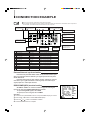
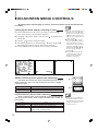
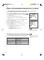
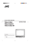
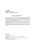
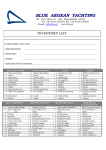
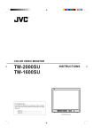
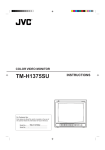
COLOR VIDEO MONITOR
BM-H1900SU
BM-H1310SU
INSTRUCTIONS
For Customer Use:
Enter below the Model No. and
Serial No. which is located on the
rear of the cabinet. Retain this
information for future reference.
UNDER PULSE COLOR BLUE MEMORY
SCAN CROSS OFF CHECK MODE
VOLUME
Model No.
PHASE
MENU
CHROMA BRIGHT CONTRAST
A
RGB/
B COMPO(SDI) Y/C
EXT
SYNC
ENTER
Serial No.
DEGAUSS
POWER
VIDEO
INPUT SELECT
ON
OFF
SAFETY PRECAUTIONS
WARNING:
INFORMATION
TO PREVENT FIRE OR SHOCK HAZARDS, DO
NOT EXPOSE THIS APPLIANCE TO RAIN OR
CAUTION: Changes or modification not approved by
JVC could void the user's authority to operate the
equipment.
MOISTURE.
NOTE: This equipment has been tested and found to
comply with the limits for a Class A digital device,
pursuant to Part 15 of the FCC Rules. These limits
are designed to provide reasonable protection against
harmful interference when the equipment is operated
in a commercial environment. This equipment
generates, uses, and can radiate radio frequency
energy and, if not installed and used in accordance
with the instruction manual, may cause harmful
interference to radio communications. Operation of this
equipment in a residential area is likely to cause
harmful interference in which case the user will be
required to correct the interference at his own
expense.
■ PRECAUTIONS
■ HANDLING
[Prevent inflammables, water and metallic objects from
entering the unit.
[Do not remodel or disassemble the unit. As the unit
incorporates circuitry generating high voltage,
physical danger and malfunctioning of the unit itself
may result.
[Remove the AC power cord from the AC outlet when
you are not using the unit for a long period.
[Do not apply shocks or vibrations. Malfunctioning of
the unit is likely to result.
[Do not block the ventilation slots.
[Do not use it in extermaly hot places. Exposed to the
direct sunlight for a long period of time or placed
near a heater, the cabinet could become deformed,
or the performance of the internal components may
deteriorate.
[Do not place the unit near appliances generating
strong electric or magnetic fields. Noisy or unstable
pictures are likely to result.
[Keep the monitor clean by wiping the cabinet and
CRT screen with a piece of soft cloth. Do not apply
thinner or benzine. These chemicals can damage the
surface finish and cause printed letters to be erased.
Clean excessive soiling with a diluted neutral
cleanser, then wipe away the cleanser with a dry
cloth.
SCREEN BURN
[It is not recommended to keep a certain still image displayed on screen for a long time as well as displaying extremely
bright images on screen. This may cause a burning (sticking) phenomenon on the screen of cathode-ray tube. This
problem does not occur as far as displaying normal video playback motion images.
2
Thank you for purchasing this JVC color video monitor.Before using it, read and follow all
instructions carefully to take fullest advantage of the monitor's performance.
CONTENTS
SAFETY PRECAUTIONS ----------------------------------- 2
FEATURES ------------------------------------------------------ 3
CONTROLS AND FEATURES (FRONT) --------------- 4
TERMINALS AND FEATURES (REAR) ---------------- 5
CONNECTION EXAMPLE ---------------------------------- 6
MEMORY MODE --------------------------------------------- 12
External/internal synchronization ------------------------- 6
To call up SET-UP MENU and select a function --- 14
RGB/COMPO(SDI) terminal setting --------------------- 6
SIZE/CENTERING (size/positioning adjustments of RGB signal pictures) -- 14
BASIC OPERATION ------------------------------------------ 7
WHITE BALANCE ADJUST (white balance adjustments) -- 15
To demagnetize the picture tube ------------------------- 7
REMOTE SELECT (TALLY/REMOTE-terminal settings) ---- 15
PICTURE ADJUSTMENTS --------------------------------- 8
STATUS DISPLAY (setting the status display to on/off) -- 16
Recall/release of memory mode ------------------------ 12
Setting programming of the picture being monitored ----- 12
Revision of memory mode ------------------------------- 12
SET-UP FOR MONITOR INSTALLATION ------------ 14
CONTRAST (picture contrast) ---------------------------- 8
CONTROL LOCK (deactivation of front-control functions) -- 16
BRIGHT (picture brightness) ------------------------------ 8
PICTURE SETTING INITIALIZATION ---------------- 17
CHROMA (picture color density) ------------------------- 8
To initialize MENU settings only ------------------------ 17
PHASE (picture hue) ---------------------------------------- 8
To initialize both MENU/SET-UP MENU settings -- 17
Relation between picture adjustments and input video signals --- 8
REMOTE CONTROLS ------------------------------------- 18
VIDEO SIGNAL CONTROLS ------------------------------- 9
On-screen menu remote operation -------------------- 18
UNDER SCAN ------------------------------------------------- 9
Picture adjustments ---------------------------------------- 18
PULSE CROSS ----------------------------------------------- 9
Sound adjustments ----------------------------------------- 18
COLOR OFF --------------------------------------------------- 9
EACH REMOTE CONTROL OF PLURAL MONITORS -- 19
BLUE CHECK ------------------------------------------------- 9
To program an ID number -------------------------------- 19
ON-SCREEN MENU CONTROLS ---------------------- 10
To call up an ID number ---------------------------------- 19
Calling up the menu display, selecting an item ----- 10
To assign a monitor ---------------------------------------- 19
ASPECT RATIO (picture aspect ratio switching) -- 10
BEFORE CALLING FOR SERVICE -------------------- 20
MENU DISPLAY CHART ---------------------------------- 21
SPECIFICATIONS ------------------------------------------- 22
FILTER SELECT (built-in filter selection) ------------ 10
PEAKING FREQ./PEAKING LEVEL (picture quality improvement) ------ 11
COLOR TEMP. (color temperature switching) ----- 11
NTSC SETUP (NTSC set-up level) -------------------- 11
COMPO. LEVEL (chrominance level setting) ------- 11
ENGLISH
AFC (switching of time constant for the AFC) ------ 11
FEATURES
■ For multiple applications with various video systems; equipped with external source
component terminals that can be bridge-connected.
■ Compatible with NTSC-3.58/4.43 MHz or PAL color systems.
■ The BM-H1900SU has a medium-high-definition picture tube that reproduces pictures
with a horizontal resolution of 750 TV lines or more .
The BM-H1310SU has a high-definition picture tube that reproduces pictures with a
horizontal resolution of 750 TV lines or more .
■ Auto white-balance stabilizer (I/K feedback circuit) maintains stable color reproduction
over long-term use.
■ A range of flexible functions includes picture aspect ratio switching (between 4:3 and
16:9), memory mode and control lock.
■ Optional exclusive wireless remote control unit enables individual operation and adjustment of up to 99-unit monitors.
3
CONTROLS AND FEATURES (FRONT)
[ BM-H1900SU ]
4 5 6 7 8
9pq we
UNDER PULSE COLOR
OFF
SCAN CROSS
VOLUME
PHASE
CHROMA
BRIGHT
BLUE MEMORY
CHECK MODE
u
MENU
(Front)
i
1
DEGAUSS
CONTRAST
POWER
VIDEO
A
RGB/
Y/C
B COMPO(SDI)
EXT
SYNC
ON
ENTER
OFF
INPUT SELECT
3
r
[ BM-H1310SU ]
4 5 6 7 8
PHASE
CHROMA
BRIGHT
y
o
2
9pq we
UNDER PULSE COLOR
OFF
SCAN CROSS
VOLUME
t
BLUE MEMORY
CHECK MODE
u
i
DEGAUSS
MENU
CONTRAST
POWER
VIDEO
A
RGB/
Y/C
B COMPO(SDI)
EXT
SYNC
ON
OFF
ENTER
INPUT SELECT
3
r
t
y
1 Tally lamp
Glows to indicate when a tally signal is input to the
TALLY/REMOTE terminal on the rear panel. (For
terminal connection, see page 15.)
2 Speaker
3 Remote control sensor
Senses infrared signals emitted from the optional
wireless remote control.
4 VOLUME control
Turn to adjust speaker volume.
5 PHASE control
Turn to adjust picture hue, using natural skin color as a
reference.
6 CHROMA control
Turn to adjust picture color density according to your
requirements.
7 BRIGHT control
Turn to adjust picture brightness according to your
requirements.
8 CONTRAST control
Turn to adjust the picture contrast according to your
requirements.
9 UNDER SCAN switch
Push to display the whole picture on screen by reducing
display area dimensions.
p PULSE CROSS switch
Push to check the retrace period (sync signal) by
delaying input signal phase.
4
o
q COLOR OFF switch
Push to eliminate color signals and display a black-andwhite picture.
w BLUE CHECK switch
Push to eliminate red and green color signals and
display a monochrome blue picture.
e MEMORY MODE switch
Push to adjust the picture by recalling the adjustment
data that you stored in memory.
r INPUT SELECT switches
Push to select a rear terminal video signal input.
t EXT SYNC switch
Push to synchronize the monitor with an external sync
signal. This function is effective regardless of signal
input.
y MENU controls
Use to operate on-screen menu functions.
u DEGAUSS switch
Push to demagnetize the picture tube.
i POWER switch
Press to turn the power on or off.
o POWER indicator
Glows to indicate that power is on.
TERMINALS AND FEATURES (REAR)
(Rear)
2 3
8 9
w
AUDIO
IN
VIDEO A
OPEN
OUT
IN
OPEN
75 ¶
VIDEO B
4
5
IN
OUT
Y/C
OUT
75 ¶
RGB/COMPO(SDI)
G/Y
OPEN
75 ¶
OPEN
75 ¶
OPEN
e
75 ¶
SYNC
B / B-Y
OPEN
7
R / R-Y
OPEN
r
75 ¶
75 ¶
TALLY/
REMOTE
FOCUS
1
6
p
q
t
1 Power socket
Connect to an AC outlet (120 V AC, 50 Hz / 60 Hz) using
the provided power cord.
2 VIDEO A terminals
Composite video signal input terminal and bridgeconnected output terminal.
3 VIDEO A termination switch
Set to OPEN for bridged connection; set to 75 Ω for
input signal only.
4 VIDEO B terminals
Composite video signal input terminal and bridgeconnected output terminal.
5 VIDEO B termination switch
Functions as for 3.
6 SYNC terminals
External sync signal input terminal and bridge-connected
output terminal. Input an external composite sync signal
to these terminals when inputting a video signal without
a sync signal, or when synchronizing the monitor with an
external sync signal.
7 SYNC termination switch
Functions as for 3.
8 Y/C terminals
Input terminal of Y/C signals and bridge-connected
output terminal.
y
q RGB/COMPO(SDI) termination switch
Functions as for 3 .
w AUDIO A terminals
Audio signal input terminal and bridge-connected output
terminal. Linked with the VIDEO A terminals so that
AUDIO A terminals and VIDEO A terminals are selected
simultaneously.
e AUDIO B terminals
Audio signal input terminal and bridge-connected output
terminal. Linked with the VIDEO B or Y/C terminals so
that AUDIO B terminals and VIDEO B or Y/C terminals
are selected simultaneously.
r AUDIO RGB/COMPO(SDI) terminals
Audio signal input terminal and bridge-connected output
terminal. Linked with the RGB/COMPO(SDI) terminals
so that AUDIO RGB/COMPO(SDI) terminals and RGB/
COMPO(SDI) terminals are selected simultaneously.
t FOCUS control
Adjustment hole exclusively for use by service
personnel. Make sure to consult qualified service
personnel for adjustment.
y TALLY/REMOTE terminal
External input terminal of a tally signal to make the tally
lamp glow, or of a remote-control signal to switch input
or picture control.
9 Y/C termination switch
Functions as for 3.
p RGB/COMPO(SDI) terminals
Input terminal of analog RGB signals or Y/B-Y/R-Y
signals and bridge-connected output terminal. For
analog RGB signals, also accepts a G signal including a
sync signal.
5
CONNECTION EXAMPLE
●Be sure to turn off each component’s power before connection.
NOTE
●The connection shown below is only an example. Terminals and their functions differ in accordance with a component to
be connected. Also read and follow the instructions for the component.
Component that outputs a
Component that outputs a
composite video signal
composite video signal
3
For audio signal input from the
Component that outputs Y/C signals
2
1
4
component connected to VIDEO A IN
8
7
~
!
For bridge-connected output of ~
AUDIO
IN
VIDEO A
OPEN
OUT
IN
VIDEO B
IN
OUT
Y/C
OPEN
75 ¶
OUT
75 ¶
@
RGB/COMPO(SDI)
G/Y
OPEN
Component that outputs
5
For audio signal input from the
component connected to VIDEO B
IN or Y/C IN
75 ¶
OPEN
75 ¶
OPEN
75 ¶
#
For bridge-connected output of @
SYNC
B / B-Y
OPEN
75 ¶
%
a sync signal
R / R-Y
6
OPEN
9
FOCUS
75 ¶
0
=
-
Component that outputs
Component that outputs
Remote control
analog RGB signals
a component signal
component
Signal(s)
Terminal
For bridge-connected output of $
TALLY/
REMOTE
$
For audio signal input from the
component connected to
RGB/COMPO(SDI) IN
Function
1 Composite video
VIDEO A IN
2 Composite video
VIDEO A OUT
Bridge-connected output of 1
3 Composite video
VIDEO B IN
Input of a composite video signal
4 Composite video
VIDEO B OUT
Bridge-connected output of 3
5 Composite sync
SYNC IN
Input of an external sync signal
Input of a composite video signal
6 Composite sync
SYNC OUT
Bridge-connected output of 5
7 Y/C
Y/C IN
Input of Y/C signals
8 Y/C
Y/C ONT
Bridge-connected output of 7
9 Analogue RGB
RGB/COMPO(SDI) IN
Input of analogue RGB signals
0 Component
RGB/COMPO(SDI) IN
Input of a component signal
- Analogue RGB or component
RGB/COMPO(SDI) OUT
Bridge-connected output of 9 or 0
= Tally/remote control
TALLY/REMOTE
Input of a tally signal or remote control signal
External/internal synchronization
Push the front panel EXT SYNC switch to ON, and the monitor operates to synchronize with an external sync signal input to the rear panel
SYNC IN terminal.
Push the switch again to OFF, and the monitor operates to synchronize with a sync signal included in a video signal (if it includes a sync
signal) input via a video input terminal.
RGB/COMPO(SDI) terminal setting
Set RGB or COMPO. on screen to match the type of video signal
input to the rear panel RGB/COMPO(SDI) IN terminals.
To input analog RGB signals, set to RGB.
To input Y, B-Y or R-Y signal, set to COMPO.
Operation:
1. Press the front panel MENU button to call up the MENU display on screen.
2. Press the ▲ or ▼ button to select RGB/COMPO(SDI).
3. Press the or button to set RGB or COMPO..
4. Press the MENU button to complete.
6
qMENU r
ASPECT RAT I O :4-3
F I LTER SELECT :COMB
PEAK I NG FREQ. :2.6MHZ
PEAK I NG LEVEL:0dB
AFC
:NORMAL
COLOR TEMP.
:6500
NTSC
SETUP
:7.5
COMPO. LEVEL
:BETA75
qMEMORY MODE r
RGB / COMPO(SDI) :RGB
ENTER
:
BASIC OPERATION
1. To turn the power on:
Push the POWER switch.
The POWER indicator glows green. The mode and color system of an input
signal are automatically discerned and displayed on screen for about 3
seconds. To turn off power, push the POWER switch again, and the
POWER indicator goes off.
VIDEO A + Input mode
NTSC + Color system
2. To select the input:
Push an INPUT SELECT switch.
Push VIDEO A, VIDEO B, RGB/COMPO(SDI) or Y/C. The mode and color
system of a selected input signal are automatically discerned and displayed
on screen for about 3 seconds.
3. To adjust the audio level:
Turn the VOLUME control to the right to increase the level, or to the left to
decrease the level.
●Relation between input mode indication and signal input/terminal
Input mode indication
Signal input/terminal
VIDEO A
Composite video signal input to VIDEO A IN
VIDEO B
Composite video signal input to VIDEO B IN
Y/C
Y/C signal input to Y/C IN
RGB
Analogue RGB signal input to RGB/COMPO(SDI) IN
COMPO(SDI)
Component signal input to RGB/COMPO(SDI) IN
●Color system indication
indication Colour system
Colour sub-carrier
frequency
3.58 MHz
Vertical scanning
frequency
NTSC
NTSC
60 Hz
PAL
PAL
4.43 MHz
50 Hz
N4.43
NTSC
4.43 MHz
60 Hz
B/W
(Indicates when a black-and-white signal is input)
NO SYNC (Indicates when no signal is input)
To demagnetize the picture tube
After positioning near the monitor a speaker (non-magnetshielded) or other equipment that generates a strong magnetic
field, or after relocating the monitor, color patches could
appear in the picture due to magnetization of the picture tube.
If this occurs, push the DEGAUSS switch to demagnetize the
picture tube.
NOTE
●This function is not effective if
activated a second time after a very
short time has elapsed. When
degaussing must be repeated,
proceed after at least 10 minutes
have passed since first degaussing.
●The optional wireless remote control
features a DEGAUSS key.
7
PICTURE ADJUSTMENTS
Turn a separate front panel control to adjust picture contrast, picture brightness,
picture color density, and picture hue respectively:
CONTRAST (picture contrast)
CONTRAST
Softer
Clearer
BRIGHT (picture brightness)
BRIGHT
Darker
NOTE
Brighter
● To adjust the CHROMA and PHASE
controls more precisely, input the
color bar signal and operate the
BLUE CHECK function as follows:
CHROMA (picture color density)
After inputting the color bar signal,
push the front panel BLUE CHECK
switch to display a monochrome
blue picture without red/green signal
components. Turn the CHROMA
and PHASE controls so that all
(four, in the example below) blue
bars have the same density and
brightness.
CHROMA
Thinner
Denser
PHASE (picture hue)
PHASE
Relation between picture adjustments and input video signals
Each picture adjustment is effective for the following video signal input:
Signal
Control
8
Composite video, Y/C
NTSC
PAL
NTSC 4.43
B/W
RGB
COMPONENT
PHASE
Yes
No
Yes
No
No
No
CHROMA
Yes
Yes
Yes
No
No
Yes
BRIGHT
Yes
Yes
Yes
Yes
Yes
Yes
CONTRAST
Yes
Yes
Yes
Yes
Yes
Yes
Blue
Black
Blue
Black
Blue
Black
Greenish
Blue
Purplish
VIDEO SIGNAL CONTROLS
Push each switch to ON or OFF for video signal control.
UNDER SCAN
Push the UNDER SCAN switch to reduce the dimensions of display
area so the whole picture is displayed on screen. Use to check the picture
frame.
PULSE CROSS
Push the PULSE CROSS switch to simultaneously display two blank
areas crossed horizontally and vertically on screen (“Pulse Cross”
display) by delaying the phase of the input signal. Use to check the
vertical retrace line period, equalizing pulse period, vertical sync period,
horizontal sync pulse, or burst signal.
NOTE
● This function is not effective for
analog RGB signal input.
COLOR OFF
Push the COLOR OFF switch to display a black-and-white picture by
inputting a luminance signal only. Use to check the noise contained in a
luminance signal or white balance.
NOTE
●This function is not effective for
analog RGB signal input.
BLUE CHECK
Push the BLUE CHECK switch to display a monochrome blue picture
by eliminating red and green signal components. Use to check or adjust
the CHROMA and/or PHASE controls.
9
ON-SCREEN MENU CONTROLS
By calling up the menu display on screen, various functions can be selected and set
as needed.
NOTE
Calling up the menu display, selecting an item
1. Press the MENU button to call up the menu display on screen (see 1
● When the menu display 1 (shown at
left below) is on screen, press the
ENTER button. The display changes
to 2 (shown below center). In this
state, you can also select the item or
change the setting.
● When the display 2 is on screen,
below). (Press again to make the display disappear.)
2. Press the ▲ or ▼ button to select an item to be set. “
” is indicated for the
selected item.
3. Press the or button to change the setting.
4. After selecting another item by pressing the ▲ or ▼ button, repeat step 3.
each time the ▼ button is pressed
while the ENTER button pressed,
the indication moves up or down on
screen (the display 3). Press the
MENU button with display 2 or 3
These settings are all kept in memory after power is turned off.
5. Press the MENU button to complete. The menu display disappears.
on screen, and the display is
restored to 1 .
● If no operation occurs for about 5
minutes after calling up the menu
display on screen, the display
disappears automatically.
qMENU r
ASPECT RAT I O :4-3
F I L TER SE LEC T :COMB
PEAK I NG FREQ. :2.6MHZ
PEAK I NG LEVEL:0dB
AFC
:NORMAL
COLOR TEMP.
:6500
NTSC
SETUP
:7.5
COMPO. L E VE L
:BETA75
qMEMORY MODE r
RGB / COMPO(SDI) :RGB
ENTER
:
1
AFC
AFC
:NORMAL
:NORMAL
2
3
ASPECT RATIO (picture aspect ratio switching)
● 4:3
The aspect ratio of the picture can be switched between 4:3 and 16:9.
When switching to “16-9” on screen, the height of the picture is slightly
reduced (see right).
Setting
Function
4-3
Standard picture aspect ratio (4:3)
16-9
Displays the picture in 16:9 aspect ratio
FILTER SELECT (built-in filter selection)
When a composite video signal of the NTSC system (excluding NTSC
4.43) is input to the monitor, either or both of two filters in the monitor can
be activated.
Setting
Function
COMB (comb filter)
Reduces colour noise in NTSC video signals for clearer pictures.
BOTH (both filters)
Both comb and trap filters function at the same time.
NOTCH (Trap filter)
Eliminates dot interference that would show up in the vertical
boundary between two different colours.
10
● 16:9
NOTE
● The function can be operated and
the indication appears only when a
composite video signal of the NTSC
system (excluding NTSC 4.43) is
input to the monitor.
ON-SCREEN MENU CONTROLS (continued)
PEAKING FREQ./PEAKING LEVEL (picture quality improvement)
Corrects the luminance signal to improve picture quality by changing
peak frequency and/or peak level depending on the video signal input to
the monitor. Use PEAKING FREQ. to set correction frequency. Use
PEAKING LEVEL to set correction level.
Setting (ferquency)
● When analog RGB signals are input
to the monitor, the indications do not
appear and the functions cannot be
operated.
Function
2.6 MHz
For composite video signal or Y/C signal.
5.0 MHz
For component video signal.
Setting (level)
0 dB to +9 dBs
NOTE
Function
Set a higher level for correction to a higher degree.
AFC (switching of time constant for the AFC)
Use to set the time constant for the AFC (auto fine-frequency control)
to correct skew distortion of video signals input via a videotape recorder
or other video equipment.
Setting
Function
NORMAL
Normal-speed correction.
FAST
Faster correction.
SLOW
Slower correction.
COLOR TEMP. (color temperature switching)
Use to set the color temperature of white balance.
Setting
Function
9300
To 9300K.
6500
To 6500K.
NOTE
● By changing the default setting of
white balance adjustment under the
SET-UP MENU display (see page
15 for adjustment), the ✻ indication
is added to the right of the setting to
indicate that the factory-preset
setting was changed.
qMENU r
ASPECT RAT I O :4-3
F I LTER SELECT :COMB
PEAK I NG FREQ. :2.6MHZ
PEAK I NG LEVEL:0dB
AFC
:NORMAL
COLOR TEMP.
:6500
SETUP
NTSC
:7.5
COMPO. LEVEL
:BETA75
qMEMORY MODE r
RGB / COMPO(SDI) :RGB
ENTER
:
NTSC SETUP (NTSC set-up level)
Use to set up the luminance signal level to match the configuration
of the video signal input to the monitor.
Setting
Function
0
For video signal with 0% luminance signal.
7.5
For video signal with 7.5% luminance signal.
NOTE
● The item and setting are indicated
on screen and the function can be
operated only when a video signal of
the NTSC system is input to the
monitor.
COMPO. LEVEL (chrominance level setting)
Use to set the chrominance level of a component video signal.
Setting
NOTE
Function
SMPTE
For component video signal input via an M videotape recorder.
BETA00
For component video signal input (set-up level:0%) via a
BETA75
For component video signal input (set-up level:7.5%) via a
BETACAM videotape recorder.
● The item and setting are indicated
on screen and the function can be
operated only when a component
video signal is input to the monitor.
BETACAM videotape recorder.
11
MEMORY MODE
A set of picture settings can be programmed in memory
for quick recall when necessary.
Recall/release of memory mode
Press the MEMORY MODE switch to recall a set of picture settings
programmed in memory.
Pressing the switch locks the functions of the front-panel PHASE,
CHROMA, BRIGHT, CONTRAST controls, and remote-control picture
adjustments not to be operated.
Press again to release memory mode.
Setting programming of the picture being monitored
The settings of the picture being monitored can be programmed in
memory.
Settings programmable in memory mode:
● Settings of the CONTRAST, BRIGHT, CHROMA and PHASE controls on the
front panel
● On-screen menu function settings (except RGB/COMPO(SDI))
● Remote-control picture adjustment settings
NOTE
● If you attempt to operate a locked
function, “MEMORY MODE ON!!”
appears on screen for approx. 2
seconds to indicate the function
cannot be operated.
NOTE
● Programmed picture settings are
kept in memory after the power is
turned off.
qMEMORY MODE r
Are you sure ?
ENTER
gYes hthen
gNo h then
1. Check the MEMORY MODE switch is off.
2. Press the MENU button.
3. Press the ▲ or ▼ button to select MEMORY MODE.
or
Then press the ENTER button.
4. ● Press the ENTER button to program.
● Press the
or
button to cancel.
NOTE
Revision of memory mode
Programmed picture settings can be revised if necessary.
1. Press the MEMORY MODE switch to activate memory mode.
2. Press the MENU button to call up display 1 on screen.
● No matter what video signal is input,
all items appear on screen. However, depending on the type of input
video signal, some functions might
not operate even if their settings are
made.
qMEMORY MODE REV I SE
P I C TURE AD JUSTMENT
ASPECT RAT I O
:4-3
F I L TER SE LEC T :COMB
PEAK I NG FREQ. :2.6MHZ
PEAK I NG LEVEL :0dB
AFC
:NORMAL
COLOR TEMP.
:6500
NTSC
SETUP
:7.5
COMPO. L E VE L
:BETA75
ENTER
:
1
12
MEMORY MODE (continued)
3. Press the ▲ or ▼ button to select a function to be revised.
Press the ENTER button after selecting PICTURE ADJUSTMENT to call up
display 2.
qMEMORY MODE REV I SE
CONTRAST
:0
BR I GHT
:0
CHROMA
:0
PHASE
:0
ENTER
:
After making all settings on screen, press the MENU button to make display
1 appear.
4. Press the
or
button to change the set level.
2
Adjustable CONTRAST, BRIGHT, CHROMA or PHASE range depends on
each set level previously stored in memory. MAX appears to indicate maximum
level that cannot be increased. MIN appears to indicate minimum level that
cannot be decreased.
●Variable setting range
Function
PICTURE
ADJUSTMENT
NOTE
Variable setting range
Default set level
CONTRAST
-20 to +20
0
BRIGHT
-20 to +20
0
CHROMA
-20 to +20
0
PHASE
-20 to +20
0
ASPECT RATIO
4:3
FILTER SELECT
COMB
16:9
BOTH
4:3
NOTCH
PEAKING FREQ.
2.6MHz
PEAKING LEVEL
0dB + 1dB · · · + 9dB
5.0MHz
AFC
NORMAL FAST SLOW
COLOR TEMP
9300
6500
NTSC SET UP
0
COMPO. LEVEL
SMPTE BETA00 BETA75
7.5
COMB
2.6MHz
0dB
NORMAL
6500
7.5
BETA75
5. With display 1 on screen, press the MENU button to make display 3
appear.
●Press the ENTER button to program.
●Press the
or
button to cancel.
● If the ENTER button is pressed after
a function other than PICTURE
ADJUSTMENT is selected, the onscreen display changes into a
single-line one. To select another
function after making a change in
function, press the MENU button to
restore display 1 .
qMEMORY MODE REVISE
Are you sure ?
ENTER
gYes hthen
gNo h then or
3
13
SET-UP FOR MONITOR INSTALLATION
When installing the monitor, make set-up adjustments required for the picture settings to match conditions where the monitor is to be used.
To call up SET-UP MENU and select a function:
1. To make 1 (SET-UP MENU) appear, with the ENTER button pressed,
press the MENU button.
2. Press the ▲ or ▼ button to select an adjustment item.
(To set STATUS DISPLAY or CONTROL LOCK, steps 3 and 4 are not
qSET-UP MENU r
S I Z E / CENTER I NG
WH I TE BALANCE AD JUST
REMOTE SELECT
S TATUS D I SPLAY : ON
CONTROL LOCK
: OFF
ENTER
:
necessary.)
3. Press the ENTER button to call up the adjustment menu 2 of a selected
1
item (e.g. WHITE BALANCE).
4. Press the ▲ or ▼ button to select a function to be adjusted.
5. Press the or button to change the setting.
6. With the display 1 on screen, press the ▲ or ▼ button to select another
function and repeat step 5.
7. Press the MENU button to complete. SET-UP MENU disappears.
qWHITE BALANCE r
RED DRIVE
:0
GREEN DRIVE
:0
BLUE DRIVE
:0
RED CUTOFF
:0
GREEN CUTOFF
:0
BLUE CUTOFF
:0
ENTER
:
To make 1 (SET-UP MENU) disappear:
Press the MENU button.
To make 2 (e.g. WHITE BALANCE) disappear:
2
NOTE
Press the MENU button twice.
● Each time the MENU button is pressed,
the previous menu is restored.
SIZE/CENTERING (size/positioning adjustments of RGB signal pictures)
For analog RGB video signal pictures, horizontal size, vertical size,
horizontal positioning and vertical positioning can be finely adjusted.
Adjustment
H.POSITION (-10,-9…0…+9, +10)
V.POSITION (-10,-9…0…+9, +10)
H.SIZE (-10,-9…0…+9, +10)
V.SIZE (-10,-9…0…+9, +10)
14
Function
+ moves the picture to right.
- moves the picture to left.
+ moves the picture down.
- moves the picture up.
+ makes the picture wider.
- makes the picture narrower.
+ makes the picture higher.
- makes the picture lower.
NOTE
● SIZE/CENTERING appears and the
function is operable only when
monitoring the picture of analog RGB
video signals.
SET-UP FOR MONITOR INSTALLATION (continued)
WHITE BALANCE ADJUST (white balance adjustments)
Before making these adjustments, select the color
temperature 9300K or 6500K on MENU.
Adjustment (level)
NOTE
● By making white balance
adjustments on SET-UP MENU, ✻
appears to the right of the COLOR
TEMP. setting on MENU
Function
RED DRIVE (-10,-9…0…+9, +10)
Adjusts the drive level of a red signal component.
GREEN DRIVE (-10,-9…0…+9, +10)
Adjusts the drive level of a green signal component.
BLUE DRIVE (-10,-9…0…+9, +10)
Adjusts the drive level of a blue signal component.
RED CUTOFF (-10,-9…0…+9, +10)
Sets the cut-off voltage of a red signal component.
(see page 11).
GREEN CUTOFF (-10,-9…0…+9, +10) Sets the cut-off voltage of a green signal component.
BLUE CUTOFF (-10,-9…0…+9, +10)
Sets the cut-off voltage of a blue signal component.
qREMOTE SELECT r
:A B
I NPUT
CNT L - 1 : UNDER SCAN
CNT L - 2 : ASPECT RAT I O
ENTER
:
REMOTE SELECT (TALLY/REMOTE-terminal settings)
Via the TALLY/REMOTE terminal, the tally lamp can be
turned on/off, or a function (selected from display 3 shown
on the right) can be operated using an external control.
3
INPUT setting indications and selected inputs
❉: indicates when deactivating the remote control via the TALLY/REMOTE terminal
Setting
Indication
NOT USE AÔB AÔY/C AÔRGB AÔCOMPO BÔY/C BÔRGB BÔCOMPO Y/CÔRGB Y/CÔCOMPO RGBÔCOMPO
∗
∗
Short-circuit
Open-circuit
A
A
A
A
B
B
B
Y/C
Y/C
RGB
B
Y/C
RGB
COMPO.
Y/C
RGB
COMPO.
RGB
COMPO.
COMPO.
CNTL-1/CNTL-2 setting indications and set positions
❉: indicates when deactivating the remote control via the TALLY/REMOTE terminal
Setting Indication NOT USE UNDER SCAN PULSE CROSS COLOR OFF BLUE CHECK EXTERNAL SYNC ASPECT RATIO COLOR TEMP. AUDIO MUTE
∗
∗
Short-circuit
Open-circuit
ON
ON
ON
ON
External
16-9
6500
ON
OFF
OFF
OFF
OFF
Internal
4-3
9300
OFF
NOTE
[TALLY/REMOTE terminal functions
All controls via TALLY/REMOTE terminal are made by short-circuiting or open-circuiting
any pin from Pin 1 to 4 and either Pin 7 or 8 (GND each) of this terminal.
When using this terminal, be sure to short-circuit Pin 5 and either Pin 7 or 8.
GND
∗1
To open-circuit
Tally lamp
To turn off
6
7
8
CNTL-1
1
3
To
short-circuit
5
To turn on
TALLY
4
2
To open-circuit
CNTL-2
To short-circuit
To open-circuit
INPUT
To
short-circuit
● When the TALLY/REMOTE terminal
is used, the following functions
become deactivated (except when
they are set to "NOT USE"):
- Front INPUT SELECT and EXT
SYNC switches
- Front UNDER SCAN, PULSE
CROSS, COLOR OFF and BLUE
CHECK switches
- On-screen MENU’s ASPECT RATIO
and COLOR TEMP. functions
- Remote MUTE key
● If a function is applied to both CNTL-1
and CNTL-2, CNTL-1 has priority.
∗1: Pin 6 is DC power output pin. It
outputs DC 5 V when the monitor’s
power is on. (Do not short-circuit pin 6
directly to ground.)
15
SET-UP FOR MONITOR INSTALLATION (continued)
STATUS DISPLAY (setting the status display to on/off)
When the power is turned on or the input mode is switched, the
status display (color system and input mode) appears on screen. The
display can be set to on or off.
Setting
Function
ON
Status display appears.
OFF
Status display does not appear.
CONTROL LOCK (deactivation of front-control functions)
Set CONTROL LOCK to ON on screen to deactivate the front-control
functions (front VOLUME control and remote volume control are operable).
Setting
ON
Function
Deactivates the front controls
(except front/remote volume controls).
OFF
Releases deactivated functions.
NOTE
● If you attempt to operate a locked
function, “CONTROL LOCK ON!!”
appears on screen for approx. 2
seconds to indicate the function
cannot be operated.
● Once CONTROL LOCK is deactivated, the current settings of the
front-control knobs and buttons are
activated.
● If the power is turned off with
CONTROL LOCK activated, the
function is kept in memory.
16
PICTURE SETTING INITIALIZATION
The MENU and/or SET-UP MENU settings, including changes added later by the user,
can be reset (initialized) to their initial (default) settings.
To initialize MENU settings only
MENU settings (except MEMORY MODE and RGB/COMPO(SDI)) can
be exclusively reset:
NOTE
● For initial (default) MENU settings,
see page 21.
1. With the ▼ button pressed, press the MENU button to display 1 on screen.
2. ● Press the ENTER button to reset.
● Press the
or
qMENU rRESET
Are you sure ?
button to cancel.
ENTER
gYes hthen
gNo h then
● MENU and PICTURE ADJUST settings (except MEMORY
MODE and RGB/COMPO(SDI)) can also be simultaneously
reset via the optional wireless remote control unit:
or
1
1. Press the MENU key to display MENU on screen.
2. Press the RESET key to execute.
To initialize both MENU/SET-UP MENU settings
MENU and SET-UP MENU settings other than MEMORY MODE and
RGB/COMPO(SDI) can be reset at the same time. In this case, PICTURE
ADJUST settings via remote control are also reset, and the monitor’s ID
number is also reset to 00.
1. Press the POWER switch to turn the power off.
2. With the ▼ and MENU buttons pressed, press the POWER switch to turn
the power on. Keep pressing the ▼ and MENU buttons until 2 appears on
qIN I T I AL IZE MENU r
ID NUMBER SET
qSET-UP MENU rRESET
ENTER
2
screen.
3. Press the ▲ or ▼ button to select SET-UP MENU RESET. Then press the
qSET-UP MENU rRESET
ENTER button to display 3 on screen.
4. ● Press the ENTER button again to execute.
● Press the
or
button to cancel.
Are you sure ?
ENTER
gYes hthen
gNo h then
or
3
17
REMOTE CONTROLS
The optional wireless remote control unit (RM-C550W) operates the following:
● On-screen menu functions (MENU, SET-UP MENU, etc.)
● Picture adjustments (CONTRAST, BRIGHT, CHROMA, PHASE)
● Sound adjustments (VOLUME, MUTE)
On-screen menu remote operation
Remote keys and front controls with the same designation share the
common functions. For detailed operation, see instructions about each
menu function in this manual.
NOTE
Picture adjustments
Each adjustable range depends on the setting of the front CONTRAST/
BRIGHT/CHROMA or PHASE control. If an adjustment is made via remote
control with the front control set approximately to the maximum or minimum,
the level may indicate a certain change on screen but may not actually
increase or decrease.
1. Press the PICTURE key to display PICTURE ADJUST.
2. Press the ▲ or ▼ key to select an item.
3. Press the or key to change the level:
: Moves the cursor to left (to decrease the level).
● When monitoring the picture of analog
RGB signals, component signal or
black-and-white signal, CHROMA and
PHASE do not appear and cannot be
adjusted.
● When a video signal of the PAL system is input to the monitor, PHASE
does not appear and cannot be adjusted.
qP I CTURE AD JUST r
CONTRAST
:0
BR I GHT
:0
CHROMA
:0
PHASE
:0
ENTER
:
: Moves the cursor to right (to increase the level).
4. Press the ▲ or ▼ key to another item and repeat step 3.
5. Press the PICTURE key to complete.
● To standardize all settings on PICTURE ADJUST:
After step 1, press the RESET key.
NOTE
● Each time the PICTURE key is pressed,
the previous display is restored.
VOLUME: @+01
Sound adjustments
A variable range depends on the setting of the front VOLUME control.
If audio level is remote-controlled with front VOLUME control set approximately to the maximum or minimum, the level may indicate a certain change
on screen but may not actually increase or decrease.
● Press the VOLUME – or + key to decrease or increase the level (within ±20).
● Press the MUTE key to mute the sound. MUTE appears on screen for
approx. 3 seconds. Press again to release.
NOTE
● If the power is turned off with soundmuting activated, the function is kept
in memory.
● To release sound-muting, turn the
front VOLUME control or press the
remote VOLUME – or + key .
18
EACH REMOTE CONTROL OF PLURAL MONITORS
To operate or adjust plural units of monitors, by programming and assigning an ID
number (00 to 99) for each monitor, a specified monitor can be remote-controlled.
To program an ID number (use front controls):
1. Press the POWER switch to turn the power off.
2. With the ▼ and MENU buttons pressed, press the POWER switch to turn
q I N I T I ALIZE MENU r
I D NUMBER SE T
qSE T - UP MENU rRE SE T
ENTER
the power on. Keep pressing the ▼ and MENU buttons until 1 appears.
3. Press the
▲ or ▼ button to select ID NUMBER SET. Then press the
ENTER button to display 2.
4. Select an ID number.
Press the
button to increase.
Press the
button to decrease.
1
qID NUMBER SET r
5. Press the ENTER button to program.
00
To call up an ID number (use remote unit):
1. Press the DISPLAY key to indicate a programmed ID number at top right of the
2
NOTE
screen.
● Red-indicated ID number:
indicates the monitor can be remote-controlled.
● ID number 00 is always indicated in
red.
● Green-indicated ID number:
indicates the monitor cannot be remote-controlled.
2. Press the DISPLAY key to make the number disappear.
To assign a monitor (use remote control):
1. Press the DISPLAY key to display the monitor’s programmed ID number.
2. Press the numeric keys to enter the monitor’s ID number.
The entered ID number appears and blinks on screen center.
Programmed
ID number
15
15
Assigned
ID number
3. Press the ID SET key to complete.
The programmed ID number in the top right of the screen turns red to indicate
the monitor was assigned. Other monitors’ ID numbers are indicated in green.
4.
After adjusting the monitor, repeat steps
2 to 4 to adjust each monitor if
necessary.
5. Press the DISPLAY key to clear on-screen ID numbers.
19
BEFORE CALLING FOR SERVICE
Before concluding a problem has occurred, check the following points. If the problem
persists after carrying out the checks, disconnect the power cord from the AC outlet and
consult the dealer from whom you purchased the monitor.
Problems
Measures
Is MEMORY MODE switched on?
Switch off.
Is CONTROL LOCK activated?
Deactivate it.
Abnormal picture adjustments
with all controls at centre.
Are PICTURE ADJUST menu
settings changed via remote
control?
Reset to standard settings.
Inoperable picture
synchronisation.
Is EXT SYNC switched on?
Switch to off.
Inoperable remote-controlled
picture adjustments.
Are the front controls set
approximately to the maximum
or minimum?
If so, the settings may not extend
any more via remote control
(although setting levels indicated
on screen may show a slight
change).
Assigned remote control ID
number operates another
monitor.
Is ID number 00 programmed for
other monitors?
Programme an ID number other
than 00.
Do other monitors indicate a red
ID number?
Assign the ID number again.
Inoperable remote control.
Is the ID number programmed
for other monitors assigned?
Assign the monitor's
programmed ID number.
No sound via audio signal input.
Does the audio input terminal
match the video input terminal?
Each audio input terminal is
linked with a video input terminal.
No INITIALIZE MENU display.
Are you pressing the ∞ and
MENU buttons until it appears?
Keep pressing these buttons until
it appears.
Inoperable CNTL-2 external
control via TALLY/REMOTE
terminal.
Is a function applied common to
CNTL-1 and CNTL-2?
Set other functions to CNTL-2.
Inoperable adjustment controls
or buttons.
20
Points to be checked
MENU DISPLAY CHART
The initial (default) adjustments/settings are shown in the menus below.
When the monitor was shipped from the factory, the NTSC SETUP had been set to 7.5
and the COMPO. LEVEL to BETA 75.
For PICTURE ADJUST MENU via remote control, see page 18.
MENU
Menu functions
qMENU r
ASPECT RAT I O :4-3
F I L TER SE LEC T :COMB
PEAK I NG FREQ. :2.6MHZ
PEAK I NG LEVEL:0dB
AFC
:NORMAL
COLOR TEMP.
:6500
SETUP
NTSC
:7.5
COMPO. L E VE L
:BETA75
qMEMORY MODE r
RGB / COMPO(SDI) :RGB
ENTER
:
Memory-Mode programming
qMEMORY MODE r
ENTER
Are you sure ?
ENTER
gYes hthen
gNo h then
or
MENU
MEMORY MODE + MENU
Memory-Mode revision menu
qMEMORY MODE REV I SE
P I C TURE AD JUSTMENT
ASPECT RAT I O
:4-3
F I L TER SE LEC T :COMB
PEAK I NG FREQ. :2.6MHZ
PEAK I NG LEVEL :0dB
AFC
:NORMAL
COLOR TEMP.
:6500
NTSC
SETUP
:7.5
COMPO. L E VE L
:BETA75
ENTER
:
Memory-Mode picture adjustments
ENTER
qMEMORY MODE REV I SE
CONTRAST
:0
BR I GHT
:0
CHROMA
:0
PHASE
:0
ENTER
:
Memory-Mode revision
qMEMORY MODE REVISE
Are you sure ?
ENTER
gYes hthen
gNo h then or
RGB-signal picture
size/positioning adjustments
ENTER + MENU
Set-up for monitor installation
qSET-UP MENU r
S I ZE / CENTER I NG
WH I TE BALANCE AD JUST
REMOTE SELECT
STATUS D I SPLAY : ON
CONTROL LOCK
: OFF
ENTER
:
ENTER
qS I ZE / CENTER I NG r
POS I T I ON
:0
POS I T I ON
:0
S I ZE
:0
S I ZE
:0
ENTER
:
H.
V.
H.
V.
White-balance adjustments
ENTER
¥ + MENU
qWHITE BALANCE r
RED DRIVE
:0
GREEN DRIVE
:0
BLUE DRIVE
:0
RED CUTOFF
:0
GREEN CUTOFF
:0
BLUE CUTOFF
:0
ENTER
:
Menu-function resetting
qMENU rRESET
Remote-terminal settings
Are you sure ?
ENTER
gYes hthen
gNo h then
or
ENTER
qREMOTE SEL ECT r
: NOT USE
I NPUT
CNT L - 1 : NOT USE
CNT L - 2 : NOT USE
ENTER
:
¥ + MENU + POWER
“Initialize” menu
q IN I T IALIZE MENU r
I D NUMBER SE T
qSE T - UP MENU rRE SE T
ENTER
ID-number programming
Menu-function standardization
qID NUMBER SET r
qSET-UP MENU rRESET
ENTER
00
ENTER
Are you sure ?
ENTER
gYes hthen
gNo h then
or
21
SPECIFICATIONS
Type
Color systems
Picture tube
: Color video monitor
: NTSC 3.58 MHz, NTSC 4.43 MHz, PAL
: [BM-H1900SU]
19" (47.5 cm) diagonally measured,
90° deflection, in-line gun, mediumhigh-definition cathode-ray tube, triodot type (dot pitch of 0.4 mm),
SMPTE-C phosphor
[BM-H1310SU]
13" (33 cm) diagonally measured,
90° deflection, in-line gun,
high-definition tinted cathode ray tube,
trio-dot type (dot pitch of 0.28 mm)
Screen size (W x H) : [BM-H1900SU]
15-11/16" x 11-3/4"
(399 mm x 298 mm)
[BM-H1310SU]
11-1/16" x 8-5/16"
(280 mm x 210 mm)
Scanning frequency : H: 15.734 kHz
(NTSC 3.58 MHz / 4.43 MHz)
15.625 kHz (PAL)
V: 59.94 Hz
(NTSC 3.58 MHz / 4.43 MHz)
50 Hz (PAL)
Horizontal resolution : 750 TV lines or more
Color temperature
: 6500 K; x = 0.313, y = 0.329
9300 K; x = 0.283, y = 0.297
(selectable)
Video inputs
: Composite video
INPUT A, B (2 lines), BNC x 2 each
(with 1 bridge-connected output)
Termination switches provided
1.0 V (p-p), 75 Ω, negative sync
: Y/C
Y/C (1 line), Mini-DIN (4-pin) x 2
(with 1 bridge-connected output)
Termination switch provided
Y: 1.0 V (p-p), 75 Ω, negative sync
C (NTSC 3.58 MHz / 4.43 MHz):
0.286 V (p-p), 75 Ω
C (PAL): 0.3 V (p-p), 75 Ω
: Analog RGB
RGB / COMPO (SDI)
(1 line: common with Y, R-Y, B-Y,
component),
BNC x 6 (with 3 bridge-connected
outputs)
Termination switches provided
R,B: 0.7 V (p-p), 75 Ω
G: 0.7 V (p-p), 75 Ω
G on sync: 1.0 V (p-p), 75 Ω, negative
sync
22
: Y, R-Y, B-Y component
RGB / COMPO (SDI)
(1 line: common with analog RGB)
Y: 1.0 V (p-p), 75 Ω, negative sync
R-Y, B-Y: 0.7 V (p-p), 75 Ω
External sync inputs : SYNC (1 line),
BNC x 2 (with 1 bridge-connected
output)
0.2 V (p-p) – 4.0 V (p-p) composite
sync, 75 Ω, negative sync
Termination switch provided
Audio inputs
: AUDIO A, B, RGB / COMPO (SDI)
(3 lines), RCA x 2 each
(with 1 bridge-connected output)
500 mV (rms), high impedance
Tally/remote terminal : TALLY / REMOTE, DIN (8-pin) x 1
Audio power output : 1.6 W
Built-in speaker
: 3-9/16" x 2" (9 cm x 5 cm) oval x 1
Operation temperature: 0 °C – 40 °C (20 % – 80 % RH)
Power requirements : 120 V AC, 50 Hz / 60 Hz
Power consumption : 0.9 A
Dimensions (WxHxD) : [BM-H1900SU]
17-3/4" x 17" x 20-1/8"
(449 mm x 431 mm x 511 mm)
[BM-H1310SU]
13-5/8" x 13-1/8" x 16-1/4"
(346 mm x 332 mm x 410 mm)
Weight
: [BM-H1900SU] 66 lbs (30 kg)
[BM-H1310SU] 35.6 lbs (16.2 kg)
Provided accessory : Power cord x 1
Optional accessories : Wireless remote control unit
(RM-C550W)
DIMENSIONS
BM-H1310SU
❋ The faceplate dimensions shown are larger than the visible portion of screen (Screen size).
13-5/8" (346mm)
MENU
DEGAUSS
CHROMA BRIGHT CONTRAST
POWER
VIDEO
A
RGB/
B COMPO(SDI) Y/C
EXT
SYNC
ON
OFF
ENTER
INPUT SELECT
3-3/8"
(83.5mm)
Front 13"(327.5mm)
Rear 11-1/8"(280mm)
BM-H1900SU
1/4"(5mm)
PHASE
1/8"(2mm)
UNDER PULSE COLOR BLUE MEMORY
SCAN CROSS OFF CHECK MODE
VOLUME
7-5/8"(193mm)
11-3/8"(287mm) *
13-1/8"(332mm)
8-5/8"(217mm)
*
16-1/4" (410mm)
9-3/8"(238mm)
❋ The faceplate dimensions shown are larger than the visible portion of screen (Screen size).
20-1/8" (511mm)
17-3/4" (449mm)
PHASE
MENU
DEGAUSS
CHROMA BRIGHT CONTRAST
POWER
VIDEO
A
RGB/
B COMPO(SDI) Y/C
EXT
SYNC
ENTER
INPUT SELECT
14-5/8"(370mm)
ON
OFF
3/8"(7mm)
UNDER PULSE COLOR BLUE MEMORY
SCAN CROSS OFF CHECK MODE
VOLUME
9-1/2"(240mm)
15-7/8"(401mm) *
1/2"(11mm)
17"(431mm)
11-3/4"(298mm)
*
3-5/8"
(91.5mm)
13-7/8"(351mm)
E. & O.E. Design and specifications subject to change without notice.
23
BM-H1900SU / BM-H1310SU COLOR VIDEO MONITOR
JVC PROFESSIONAL PRODUCTS COMPANY
DIVISION OF US JVC CORP.
1700 Vallery Road Wayne, NJ07470
JVC CANADA INC.
21 Finchdene Square, Scarborough Ontario M1X 1A7
C 1999 VICTOR COMPANY OF JAPAN, LIMITED
Printed in Japan
LCT0696-001A
1199-Tu-V-Ni