1
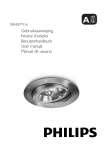
VN-T216VPRU
FIXED HD IP DOME CAMERA
QUICK GUIDE
Contents
1
Introduction .......................................................................................................................... 2
Unpack Everything ................................................................................................................. 2
Preparation ............................................................................................................................ 2
Camera Installation................................................................................................................. 2
Disassembling the Camera ............................................................................................... 3
Connecting the Wiring....................................................................................................... 3
Adjusting the Camera Position........................................................................................... 5
Mounting the Camera ....................................................................................................... 6
Locking the Camera.......................................................................................................... 8
Network Configuration: Setting Network Camera Environment ................................................. 8
Setting IP ......................................................................................................................... 8
Connecting the Camera to a Personal Computer ................................................................ 8
Using “IP Finder” to Search Camera’s IP Address............................................................. 11
2
Notice of Use ...................................................................................................................... 12
3
Warnings ............................................................................................................................ 13
4
Dimensions ........................................................................................................................ 13
5
Specifications..................................................................................................................... 14
n Contents of this manual
•
•
•
•
•
Windows and Internet Explorer are registered trademarks of
Microsoft Corporation in the U.S.
Pentium is a registered trademark of Intel Corporation in the U.S.
AMD is trademark of Advanced Micro Devices Inc. in the U.S.
Product names of other companies described in this manual are
trademarks or registered trademarks of the respective companies.
Symbols such as ™ , ® and © are omitted in this manual.
Design, specifications and other contents described in this manual
are subject to change for improvements without prior notice.
1
1 Introduction
Thank you for purchasing the camera. Before installing it, read the guide carefully and check the
model.
For more information, please refer to the INSTRUCTIONS on CD-ROM.
Unpack Everything
Ÿ
Ÿ
Ÿ
Ÿ
Ÿ
Ÿ
Ÿ
Ÿ
Ÿ
Ÿ
Ÿ
Ÿ
FIXED HD IP DOME CAMERA
WARRANTY CARD
SAFETY PRECAUTIONS
QUICK GUIDE
2-PIN TERMINAL BLOCK for power input, and 8-PIN TERMINAL
BLOCK for alarm input/output
CD-ROM containing INSTRUCTIONS and IP Finder software
TEMPLATE : mounting template
WRENCH : Hexagon screw driver
3 SCREW ANCHORs
3 SCREWs
SCREW (for WIRE)
WASHER (for WIRE)
Preparation
The following tools might help you to complete the installation:
•
Drill
•
Screwdrivers
•
Wire cutters
Camera Installation
All the installation and operations here should conform to your local electricity
Note
safety rules.
2
Disassembling the Camera
•
Gently remove the screw to take off camera housing (4).
•
Set the camera housing (5) and liner aside.
Connecting the Wiring
Connect the power supply cable to the power connectors.
Select one of the following options.
Ÿ
Inset power cable for AC24V
Connect 24 V (~) cables to terminals ~AC24V.
Ÿ
PoE
Connect the network cable to the RJ45 terminal using a switch.
Note
Connectors and field wiring terminals for external Class 2
circuits provided with marking indicating minimum Class of
wiring to be used. Class 2 shall be marked adjacent to the
field wiring terminals.
3
Washer (for Wire)
Screw (for Wire)
Safety Wire
(Fall Prevention Wire, not
supplied)
Ÿ
Connect the wiring then place the camera to a proper position by
pushing the button.
4
Adjusting the Camera Position
The dome camera has three axes for positioning the camera. While monitoring the picture on the
monitor, adjus t the camera position as follows:
•
Pan Adjustment (A) For Wall Mount and Tilted Ceilings Rotate the lens base
(maximum360° ) until you are satisfied with the field of view.
•
Horizontal Rotation (B) Rotate 3D assembly in the base. Do not turn assembly more than
360° as this assembly may cause the internal cables to twist and disconnect or break.
•
Tilt Adjustment (C) After loosening the thumbnuts, position the camera as desired, then
finger –tighten the thumbnuts to set the position.
Caution
Do not turn the lens more than 360° as this may cause internal cables to
disconnect or break.
Caution
Retighten the locking screws to prevent loss of adjustment.
5
Mounting the Camera
Ÿ
Place the guide pattern sticker (supplied) on the mounting surface and
mark three holes according to the guide pattern sticker. Then fasten the
sticker to the mounting surface with screws.
Ÿ
Connect the Safety Wire (Fall Prevention Wire, not supplied) to the camera
and the ceiling.
Ÿ
Secure the camera bottom case (1) to the wall/ceiling with tapping screws,
supplied.
Ÿ
Adjust the view angle (zoom, focus, and Horizontal Rotation).
To prevent the camera from falling off, ensure that it is connected to a firm place
(ceiling slab or channel) using a Safety Wire (Fall Prevention Wire is not
supplied).
Warning
Pay also careful attention to the length, strength, wiring, and material (insulating
properties) of the fall prevention wire to be used. The length should be as short
as possible within the permissible range of the mounting length. The wire
should be strong enough to withstand the total weight of this product. (Pay also
attention to the finishing at the end of the wire.)
Caution
Must be isolated camera and the wall/ceiling which are connected by the Safety
Wire (Fall Prevention Wire).
Safety Wire
(Fall Prevention Wire, not supplied)
6
l
4S Electrical junction box(Optional)
1.
Secure the mounting kit (optional) to 4S Electrical box using 2 appropriate
screws.
2.
Then secure the camera case to mounting kit using 2 appropriate screws.
3.
Tuck the cables in the 4S Electrical box.
4.
Adjust the view angle (zoom, focus, and Horizontal Rotation).
5.
Attach the camera housing.
6.
Turn the power on after you have installed the camera.
This mounting kit
is optional
accessory.
Depending on the material of your mounting surface, you may require different
Note
screws and anchors than those supplied.
If tilt angle is less than 20 degrees from the horizontal, the image can flash by
Note
reflection of IR-LED light. Keeping tilt angle over 20 degrees is recommended
when IR-LED light is used.
7
Locking the Camera
•
Use soft, lint -free cloth to wipe the dome cover clean and remove fingerprints.
•
Attach the inner liner and camera housing.
•
Turn the power on after you have installed the camera.
Network Configuration: Setting Network Camera Environment
Setting IP
This is a network-based camera and must be assigned an IP address first.
The camera’s default IP address is 192.168.0.2 and sub mask is 255.255.255.0. To change
IP address, open Network Settings page described later.
If your network uses a DHCP server, an IP address can be assigned automatically from the
DHCP server by enabling DHCP in the Network Settings page described later.
Connecting the Camera to a Personal Computer
1.
Connect the network cable to the camera and then turn on the camera’s power.
2.
Set the personal computer’s IP address. The camera’s default IP address is 192.168.0.2 and
sub mask is 255.255.255.0.
3.
Check that the camera and computer are connected by pinging the IP address you have set. To
do this, start a command prompt (Windows: from the Start Menu, select Program. Then select
Accessories and choose Command Prompt.) Type: Ping 192.168.0.2. If the message “Reply
from… ” appears, it means the connection is done.
4.
Start Internet Explorer and enter IP address: 192.168.0.2. A login window will appear. Enter the
default user name: admin and password: jvc to log in.
5.
Images of the camera can be viewed through Internet Explorer. Before viewing, follow these
steps to enable the display.
a.
Enable Cookies as shown below:
8
• In Internet Explorer, click Internet Options on the Tools menu.
• On the Privacy tab, move the settings slider to Low or Accept All Cookies .
• Click OK.
b.
When a proxy server is used, click Internet Options on the Tools menu of
Internet Explorer, select Connect tab, click LAN button, and set proxy server.
c.
Change Security in Internet options as shown below:
• On tool menu, click Internet Option.
• Press the Security tab.
• If the camera operates inside the Intranet, click the Intranet icon. If the camera
operates on the Internet, click the Internet icon.
•
In Windows 7 only, Click【Tools 】è【Internet Options 】è【Security】
Enable Protected Mode (require restarting Internet Explorer) è Unchecked
• Click Custom Level. This will open the Security Settings – Internet Zone
screen.
• Scroll down to the ActiveX controls and plug-ins radio buttons and set as
follows :
【Download signed ActiveX controls】è Prompt (recommended)
【Download unsigned ActiveX controls】è Prompt
【Initialize and script ActiveX not marked as safe for scripting】è Prompt
9
【Automatic prompting for ActiveX controls】è Enable
【Run ActiveX controls and plug-ins 】è Enable
【Script ActiveX controls marked safe for scripting*】è Enable
• Press OK to save the settings. Close all Internet Explorer windows and start a
new window. This will allow the new settings to take effect.
6.
Type your setting IP address into the brows er.
7.
Then you should be able to see the camera image screen.
10
Using “IP Finder” to Search Camera’s IP Address
The IP Finder is a tool which helps users to find VN-T16/216 series network cameras in the LAN
which your computer is connected. Please note that IP Finder is only compatible with Windows 7,
windows Vista and Windows XP.
1.
Insert the CD-ROM in the CD-ROM drive.
2.
Copy the IP Finder’s folder to your computer.
3.
Double click the IpFinder.exe in your computer’s IP Finder folder. An IP Camera Finder
window will pop out. The window will display a list of IP cameras which you are using
currently.
4.
Press Search to search cameras.
11
2 Notice of Use
•
This manual is designed for administrators and users of the network camera. Please read it
carefully before use. All requirements should be followed before using this camera.
•
Keep this document for future reference.
•
Please make sure the power source is AC24V / PoE. Only connect the camera to this power
system.
•
The camera must be installed on a solid mounting surface.
•
Keep the camera and other accessories dry.
•
We are not responsible for any damage caused by inappropriate use.
•
Because the camera controls auto exposure by shutter speed, flicker can be shown by
fluorescent light. To reduce the flicker, please select PAL mode if the power is 50Hz, or NTSC
mode if the power is 60Hz. (Refer to INSTRUCTIONS “4 Overview of Navigation and
Controls ” - “Video Type”)
12
3 Warnings
Installation and maintenance should be performed only by qualified and experienced technicians
to conform to all local codes and to maintain your warranty.
DANGER! AC24V models require the use of CSA Certified/UL Listed Class 2 power adapters to
ensure compliance with electrical safety standards. Power over Ethernet (PoE) should meet the
IEEE 802.3af PoE standard.
4 Dimensions
13
5 Specifications
Operational Specifications
Image device
1/2.7-type Mega-pixel CMOS sensor
Sensitivity
Color:0.6 lx, B/W: 0 lx (50% )
Day/Night
True D/N
IR-LED
Yes (IR Distance 15m)
Auto Gain Control
Off/On, selectable
White Balance
ATW (2800K∼8500K) and Manual
PAL:1/25~1/10000 sec
Electric Shutter
NTSC: 1/30~1/10000 sec
Noise Reduction
Yes
3 Axis Gimbals
Yes
Motion detection
Yes
Lens Type
1/3-type 3-9mm F:1.2 IR cut filter built-in
BLC
Yes
Audio
Line in/out
Alarm
1 in / 1 out (Alarm out spec: 0.5A / AC120V max)
IP Specifications
Video Compression
H.264 & MPEG4 & MJPEG
Real time stream:
Video Streaming
1080P H.264 or 720P H.264+D1 or D1+D1
Independent controllable frame rate and
bandwidth. Constant or variable bitrate control
14
NTSC: 1080P(1920 x 1080), 720P(1280 x 720),
D1(720 x 480), 4CIF(704 x 480), VGA(640 x 480),
CIF(352 x 240), QVGA(320 x 240)
Resolution
PAL: 1080P(1920 x 1080), 720P(1280 x 720), D1(720
x 576), 4CIF(704 x 576), VGA(640 x 480), CIF(352 x
288), QVGA(320 x 240)
PAL: Up to 25fps
Image Frame Rate
NTSC: Up to 30fps
Security
Multiple user access levels with password
protection
Users
1 Administrator, 5 Users
Video Access from
Full control of all camera settings available to
Web Browser
administrator
Windows XP or Windows 7 as OS,
Minimum Web
Internet Explorer Version 6.0-8.0,
Browsing
CPU: Intel Pentium IV X2 2.4 GHz or equivalent
Requirements
AMD,
Memory: 1G or above
Supported Protocols
Network interface
IPv4, HTTP, TCP, RTSP, RTP, ICMP, UDP, IGMP,
RTCP, FTP, DNS, DHCP, ARP
RJ-45, 100BASE-TX/10BASE-T,
FULL/HALF/Auto negotiation
Surveillance Protocol
ONVIF Compatible (pass compliance test tool)
Onboard Storage
SDHC (suggest class 10)
Electrical
Power Supply
PoE IEEE 802.3af Class 0, AC24V
Power Consumption
PoE 0.15A, AC24V 800m A
Mechanical
Dimension
Ø155mm x 112.7mm
15
Weight
1360g
Power Input: removable terminal block
Network: RJ45 connector
Connectors
Audio In/out: removable terminal block
Alarm In/out: removable terminal block
Environmental
Operating
Temperature
©
-10°C to 50°C
Operating Humidity
0% to 90%
Storage Temperature
-20°C to 60°C
2012 JVC KENWOOD Corporation
16