1
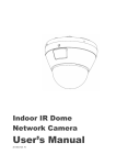
FIXED IR DOME CAMERA TK-T2101RU
FIXED IR DOME CAMERA TK-T2101RE
Instructions
Important Safety Information
Warning and Operating Notes
Installation and serving the camera should be performed only by qualified and
experienced technicians to conform to all local codes and to maintain your warranty.
WARNING!
The use of CSA certified/ UL Listed Class 2 power adapters
are required to ensure compliance.
Note:
This product is intended to be supplied by a Listed Direct Plug-In Power Unit marked
“Class 2” or Listed Adapter marked “L.P.S.” (or “Limited Power Source”) and rated
output DC 12V, 0.415A minimum or AC 24V, 60Hz, 0.415A minimum. (for USA)
WARNING!
To reduce the risk of fire or electric shock, do not expose the
product to rain or moisture.
Caution
Connect only one camera to the power line, AC24V/DC12V.
Do not share the power line with other equipment. The
power cable between power source and the camera must
be under 3 m.
Operating Notes
Power Supply: This dome camera can operate on AC 24V or DC 12V.
Note
Connectors and field wiring terminals for external Class 2
circuits provided with marking indicating minimum Class
of wiring to be used. Class 2 shall be marked adjacent to
the field wiring terminals .
Operating Conditions
• Avoid viewing very bright objects (example, light fixtures) for extended periods.
• Avoid operating or storing the unit in the following locations:
-- Extremely humid, dusty, hot, cold environments (where the operating
temperature is outside the recommended range of 14°F to 122°F [-10°C to
+50°C].)
-- Close to sources of powerful radio or TV transmitters
-- Close to fluorescent lamps or objects reflecting light
-- Under unstable light sources (may cause flickering)
1
TABLE OF CONTENTS
1. Introduction................................................................................... 3
1.1
1.2
1.3
1.4
Before You Begin-----------------------------------------------------------------Dimensions-----------------------------------------------------------------------Names of Camera Parts---------------------------------------------------------Routine Maintenance-------------------------------------------------------------
3
3
4
4
2. Installation.................................................................................... 5
2.1
2.2
2.3
2.4
2.5
2.6
2.7
Disassembling the Camera------------------------------------------------------Connecting the wiring-----------------------------------------------------------Mounting the Camera------------------------------------------------------------Optional Camera Settings-------------------------------------------------------Adjusting the Camera Position--------------------------------------------------Adjusting the Lens---------------------------------------------------------------Completing the Installation------------------------------------------------------
5
6
6
7
8
8
9
3. OSD Settings................................................................................10
3.1 Lens------------------------------------------------------------------------------ 10
3.2 SHUTTER/AGC------------------------------------------------------------------- 10
3.3 WHITE BAL----------------------------------------------------------------------- 11
3.4 BACKLIGHT---------------------------------------------------------------------- 12
3.5 PICT ADJUST--------------------------------------------------------------------- 12
3.6 ATR*------------------------------------------------------------------------------ 12
3.7 MOTION DET--------------------------------------------------------------------- 12
3.8 PRIVACY ------------------------------------------------------------------------- 12
3.9 DAY/NIGHT----------------------------------------------------------------------- 13
3.10 NR------------------------------------------------------------------------------- 13
3.11 CAMERA ID--------------------------------------------------------------------- 13
3.12 LANGUAGE---------------------------------------------------------------------- 13
3.13 CAMERA RESET----------------------------------------------------------------- 13
3.14 SAVE ALL----------------------------------------------------------------------- 13
2
INTRODUCTION
1. Introduction
The dome camera is ideal for indoor installation in commercial and residential
environment. With 3-axis mount support, it provides flexible installation on a ceiling
or wall even at an angle.
1.1 Before You Begin
Please read this manual carefully before you install the dome camera. Keep this
guide for future reference.
1.2 Dimensions
84mm
97mm
112mm
3
INTRODUCTION
1.3 Names of Camera Parts
a
b
Figure 1-1 Camera parts
1.Conduit hole used for surface run power/video connector
2.Bottom case
3.Camera housing
4.Dome cover
5.IR board
a. AC 24V / DC 12V power input connector (red +, black -)
b. Video output connector
Note: See Figure 2-3 for camera board controls.
1.4 Routine Maintenance
• The dome cover is an optical part. Use a soft, dry cloth to remove any fingerprints
or dust.
• Clean the camera housing with a soft, dry cloth. For more stubborn stains, use a
cloth dampened with a small quantity of neutral detergent, then wipe dry.
Caution: Do not use volatile solvents such as alcohol, benzene or thinners to avoid
damaging the surface finish.
4
INSTALLATION
2. Installation
2.1 Disassembling the Camera
Before you mount and adjust the camera, follow these steps to disassemble the
camera.
1.Insert a coin or flat tool to the side hole and twist to remove the dome cover.
2.Remove the dome cover (#2).
1.Bottom case
2.Dome cover
Figure 2-1 Disassemble the camera
5
INSTALLATION
2.2 Connecting the wiring
Refer to Figure 1-1 to connect the video connect output connector (#b) and 24
VAC/12 VDC power connector (#a).
Caution: For DC power supply use, make sure the polarity is correct to avoid
malfunction and / or camera damage.
2.3 Mounting the Camera
1.Attach the mounting template to the wall or ceiling.
2.Drill two holes, then insert the screw anchors (#1) into the holes.
3.Secure the bottom case to the wall or ceiling with the TP4 x 15 mm tapping
screws supplied (#2).
4. To prevent the camera from falling off, ensures it is connected to a firm place
(ceiling slab or channel) using a Safety Wire (fall prevention wire#3 is not
supplied).
Note: Depending on the material of your mounting surface, you may require different
screws and anchors than those supplied.
③
Safety Wire (fall prevention
wire#3 is not supplied).
①
Please tighten a safety wire
using plastic band on a firm
place as photo.
Safety Wire
Plastic Band
②
1.Screw anchors (x2), supplied
2.TP4 x 15 tapping screws (x2),
supplied
3. Safety Wire(fall prevention
wire, not supplied)
Figure 2-2 Camera installation
6
INSTALLATION
2.4 Optional Camera Settings
Refer to Figure 2-3 to locate the OSD joystick control on the camera board. Use the
joystick to access the OSD menu and configure the camera settings as required.
To use the OSD joystick control:
• Press the OSD joystick control straight down to enter the Main menu or a selected
item.
• Move the OSD joystick control UP, DOWN, LEFT and RIGHT to navigate through
menus and options.
For further information on OSD settings, refere to the “3. OSD Settings” section.
1. Monitor out
2. OSD Joystick Control
3. Camera mounting holes
Figure 2-3 Camera adjustment controls
7
INSTALLATION
2.5 Adjusting the Camera Position
The dome camera has three axes for positioning the camera. While monitoring the
picture on the monitor, adjust the camera position as follows:
Horizontal Adjustment Rotate 3D assembly in the base. Do not turn assembly
more than 360° as this may cause the internal cables to twist and disconnect or
break. Before making horizontal adjustment, please adjust vertical adjustment to 90
degree (vertical) first.
Vertical Adjustment After loosening the screw on the bracket, position the camera
as desired, then tighten the screw back to the bracket.
Horizontal Rotation For wall mount and tilted ceilings, rotate the lens base
(maximum 360°) until you are satisfied with the field of view.
1.Rotate 3D assembly in base for
horizontal adjustment
2.Tilt adjustment bracket and screw
for vertical adjustment
3.Axis ring for horizontal rotation
for wall mount and tilted ceilings
Figure 2-4 Camera adjustment
2.6 Adjusting the Lens
1.Loosen the focus lever counter-clockwise a little, then adjust the focus for
optimum picture sharpness.
2.Loosen the zoom lever counter-clockwise a little, then rotate the zoom lever and
determine the image view.
3.Re-tighten the zoom lever and focus lever after adjustment.
Note: It is important that you lock the zoom and focus levers after making
adjustments. This will avoid the positions moving (for example, from temperature
changes or vibrations).
8
INSTALLATION
2.7 Completing the Installation
Once all adjustments are done, attach and secure the camera housing:
1.Use a soft, lint-free cloth to wipe the dome cover clean and remove fingerprints.
2.Assemble the dome cover (#2) and the bottom case (#1).
Figure 2-5 Completing the installation
9
OSD SETTINGS
3. OSD Settings
Use the OSD menu to set up the camera for optimum performance.
LENS
SHUTTER/AGC AUTO
AUTO
PRIVACY
DAY/NIGHT
OFF
AUTO
WHITE BAL
BACKLIGHT
ATW
OFF
NR
CAMERA ID
OFF
PICT ADJUST
ATR
MOTION DET
OFF
OFF
SYNC
LANGUAGE
CAMERA RESET
NEXT
EXIT
SAVE ALL
BACK
EXIT
INT
ENGLISH
SAVE ALL
Figure 3-1 OSD Main Menu
3.1 Lens
The LENS settings allows you to configure Lens and brightness. Options are AUTO (Auto
Iris lens) and MANUAL. The default setting is AUTO.
In the AUTO submenu, you can set the MODE as OPEN, CLOSE or AUTO. Then select
SPEED to adjust the DC Iris Lens convergence speed.
TYPE
MODE
DC
OPEN
SPEED
046
3.2 SHUTTER/AGC
You can set the SHUTTER/AGC as AUTO or MANUAL. The default setting is AUTO.
When LENS is set to AUTO: It is recommended to set SHUTTER/AGC to AUTO
mode. In the AUTO submenu, adjust HIGH LUMINANCE MODE mode according to
your application:
• AUTO IRIS mode: Use this for normal condition application environments. The
IRIS level will be controlled by camera brightness.
• SHUT+AUTO IRIS mode: Use this for high light application environments. The
exposure will be controlled by AES or the DC Iris. The iris level will be controlled
by camera brightness.
HIGH LUMINANCE
MODE
BRIGHTNESS
AUTO IRIS
024
LOW LUMINANCE
MODE
BRIGHTNESS
AGC
x0.25
10
OSD SETTINGS
If SHUTTER/AGC is set to MANUAL, the submenu is shown as below. The shutter
speed is a variable from 1/50(1/60)sec to 1/10000sec and the AGC is selectable
depending on your environment condition.
MODE
SHUTTER
SHUT+AGC
1/50(1/60)
AGC
6.0
Recommended settings according to the application:
1. Auto Exposure by Iris Control:
• Application: General Purpose, Indoor surveillance. This is default settings.
• LENS: AUTO
• SHUTTER/AGC: AUTO
• HIGH LUMINANCE MODE: AUTO IRIS
2. Auto Exposure by AES first, then by IRIS Control:
• Application: Outdoor, Traffic surveillance
• LENS: AUTO
• SHUTTER/AGC: AUTO
• HIGH LUMINANCE MODE: SHUT AUTO IRIS
3. Auto Exposure by Iris Control with fixed Shutter Speed:
• LENS: AUTO
• SHUTTER/AGC: MANUAL
• SHUTTER 1/50 (1/60) ~ 10000
After this, the following are set
• SHUTTER/AGC: AUTO
• HIGH LUMINANCE MODE: SHUT+AUTOIRIS
3.3 WHITE BAL
WHITE BALANCE controls color on the screen. Options include ATW (Auto White
Balance), PUSH, PUSH LOCK, USER1, USER2, ANTI CR (Anti Color Rolling
Suppression) and MANUAL. The default is ATW.
• ATW: Select ATW when the scene illumination varies between indoor scenes and
outdoor scene lighting.
SPEED
171
DELAY CNT
ATW FRAME
ENVIRONMENT
152
X0.50
INDOOR
• MANUAL: You can manually adjust the LEVEL from 15 to 69.
• USER1/USER2: You can adjust blue setting (B-GAIN) and red setting (R-GAIN)
value from 0 to 255.
11
OSD SETTINGS
• PUSH: When selected in the appropriate position, the whole area will perform
white balance.
• PUSH LOCK: When selected in the appropriate position, WHITE BALANCE will
perform once.
3.4 BACKLIGHT
Set Backlight compensation function. It controls the light level to overcome
sever backlight conditions. Available options include OFF, BLC or HLC (Highlight
Compensation) mode. The default is OFF.
If HLC is selected, HLC is activated automatically when the camera detects highluminance.
3.5 PICT ADJUST
PICTURE ADJUST allows you to adjust picture settings for optimal image. In the PICT
ADJUST submenu, you can adjust BRIGHTNESS, CONTRAST, SHARPNESS, HUE and
GAIN value. In addition, you can set MIRROR to ON to reflect the image.
MIRROR
BRIGHTNESS
OFF
000
CONTRAST
SHARPNESS
HUE
128
128
128
GAIN
128
3.6 ATR*
Set ATR (Adaptive Tone-curve Reproduction) function. You can select ON or OFF. The
default is OFF. If selecting ON, you will enter the ATR submenu, where you can set
LUMINACE and CONTRAST to optimize by image.
LUMINANCE
CONTRAST
LOW
LOW
*Also known as Wide Dynamic Range. This function expands the video dynamic range
of the camera and improves visibility of images even in high contrast environments.
3.7 MOTION DET
MOTION DET allows to detect moving objects on the screen. The default is OFF. If
selecting ON, you will enter the MOTION DET submenu. You can set up to 4 motion
areas to detect moving objectives and adjust the motion detection sensitivity from 0
to 127.
3.8 PRIVACY
PRIVACY function mask up to 8 privacy areas on the screen from video monitoring.
The default setting is OFF. If selecting ON, you will enter the PRIVACY submenu. You
can configure up to 8 privacy areas and set color and transparency of the privacy
zones. In addition, you can enable MOSAIC function for the privacy zone.
12
OSD SETTINGS
Note: If you enable MOTION DET function, then PRIVACY function will support 4
zones only.
REA SEL
TOP
BOTTOM
1/8
000
000
LEFT
RIGHT
COLOR
000
000
1
TRANSP
MOSAIC
0.00
OFF
3.9 DAY/NIGHT
The camera will automatically switch to B/W mode when the illumination is under a
certain threshold. There is no need to adjust this setting.
Under B/W mode, you can set BURST to be ON or OFF.
3.10 NR
NR allows you to configure the DNR (Digital Noise Reduction) settings to reduce noise
on the screen. In the NR submenu, you can enable the NR MODE to the Y (BRIGHT) /
C (COLOR), C LEVEL or Y LEVEL mode. According to your NR mode, you can adjust Y
LEVEL or C LEVEL as required.
NR MODE
Y/C
Y LEVEL
C LEVEL
000
000
Note: When the Y/C Level is higher, the noise in dark areas become lessened. Also,
resolution will become lower. When it is lower, there are more noise in dark areas.
3.11 CAMERA ID
CAMERA ID allow you to specify camera ID. Options are OFF (default) and ON. In the
ON submenu, you can add a camera title up to 26 characters with 2 lines and also
select where the title appears on the monitor screen.
3.12 LANGUAGE
OSD supports 8 multiple languages. Options include ENGLISH (default), JAPANESE,
GERMAN, FRENCH, RUSSIAN, PORTUGUESE, SPANISH and SIMPLIFIED CHINESE.
3.13 CAMERA RESET
To restore factory defaults, select CAMERA RESET and then press the joystick control.
3.14 SAVE ALL
SAVE ALL item allows you to save all settings and exit the OSD menu.
13
SPECIFICATIONS
Signal System
NTSC
PAL
Image System
Image Pickup Device
1/3 type: IT CCD
Effective Pixels (HxV)
976 (H) × 494 (V)
976 (H) × 582 (V)
2:1 Interlace V: 59.94 Hz , H:
15.734KHz
2:1 Interlace V: 50 Hz , H:
15.625 KHz
Electric
Scanning System
Sync System
Internal
Horizontal Resolution
600 TV lines
Bulit-in Lens
f=2.8mm~10.5mm,F1.2 DC iris varifocal
Horizontal:101.8°(wide)~27.4°(tele)
Vertical:73.7°(wide)~20.6°(tele)
View Angle
IR Distance
15 m
IR Wave length
850nm
Minimum Illumination
IR LED ON 0 lx (Color/B&W switch point 20lx typ.)
S/N Ratio
50dB typ. (AGC off)
Electric shutter
1/60 sec
Video Output
1/50 sec
1Vpp composite output, 75 Ω
Power Supply
Power Requirement
DC 12V & AC 24V (50Hz/60Hz) ± 10%
Power Consumption
DC12V 415mA
Environment
Operating Temperature
-10°C ~ 50°C
Operating Humidity
90% MAX
Storage Temperature
-20°C ~ 60°C
Storage Humidity
90% MAX
Mechanism
Dimension(ΦxH)
Φ112mmx97mm (4.41”x 3.82”)
Weight
Accessories
300g approx.
FIXED IR DOME CAMERA
×1
INSTRUCTIONS
×1
INSTRUCTIONS
×1
SAFETY PRECAUTIONS
×1
SAFETY PRECAUTIONS
×1
WARRANTY CARD
×1
TEMPLATE
×1
TEMPLATE
×1
SCREW
×2
SCREW
×2
SCREW ANCHOR
×2
SCREW ANCHOR
×2
MONITOR CABLE
×1
MONITOR CABLE
×1
14
14
©2012 JVC KENWOOD Corporation
FIXED IR DOME CAMERA×1