1
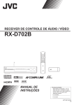
AUDIO / VIDEO CONTROL RECEIVER
RX-D401S / RX-D402B
For Customer Use:
Enter below the Model No. and Serial
No. which are located either on the rear,
bottom or side of the cabinet. Retain this
information for future reference.
INSTRUCTIONS
Model No.
Serial No.
LVT1436-001A
[J]
cover_RX-D401S[J]_f.p65
3
05.7.1, 7:58 PM
Warnings, Cautions, and Others
Mises en garde, précautions et indications diverses
CAUTION
RISK OF ELECTRIC SHOCK
DO NOT OPEN
CAUTION:
TO REDUCE THE RISK OF ELECTRIC SHOCK,
DO NOT REMOVE COVER (OR BACK).
NO USER SERVICEABLE PARTS INSIDE.
REFER SERVICING TO QUALIFIED SERVICE PERSONNEL.
The lightning flash with arrowhead symbol,
within an equilateral triangle is intended to
alert the user to the presence of uninsulated
"dangerous voltage" within the product's
enclosure that may be of sufficient
magnitude to constitute a risk of electric
shock to persons.
The exclamation point within an equilateral
triangle is intended to alert the user to the
presence of important operating and
maintenance (servicing) instructions in the
literature accompanying the appliance.
WARNING: TO REDUCE THE RISK OF FIRE
OR ELECTRIC SHOCK, DO NOT EXPOSE
THIS APPLIANCE TO RAIN OR MOISTURE.
CAUTION
To reduce the risk of electrical shocks, fire, etc.:
1. Do not remove screws, covers or cabinet.
2. Do not expose this appliance to rain or moisture.
ATTENTION
Afin d’éviter tout risque d’électrocution, d’incendie, etc.:
1. Ne pas enlever les vis ni les panneaux et ne pas ouvrir le
coffret de l’appareil.
2. Ne pas exposer l’appareil à la pluie ni à l’humidité.
Caution––
STANDBY/ON button!
Disconnect the mains plug to shut the power off completely. The
STANDBY/ON button in any position does not disconnect the
mains line. The power can be remote controlled.
Attention—Touche
STANDBY/ON!
Déconnectez la fiche d’alimentation secteur pour couper
l’alimentation complètement. La touche
STANDBY/ON,
dans n’importe quelle position, ne déconnecte pas le système
du secteur. L’alimentation ne peut pas être télécommandé.
For Canada/pour le Canada
CAUTION: TO PREVENT ELECTRIC SHOCK, MATCH WIDE
BLADE OF PLUG TO WIDE SLOT, FULLY INSERT
ATTENTION: POUR EVITER LES CHOCS ELECTRIQUES,
INTRODUIRE LA LAME LA PLUS LARGE DE LA FICHE DANS LA
BORNE CORRESPONDANTE DE LA PRISE ET POUSSER
JUSQUAU FOND
For U.S.A
This equipment has been tested and found to comply with the limits
for a Class B digital device, pursuant to part 15 of the FCC Rules.
These limits are designed to provide reasonable protection against
harmful interference in a residential installation.
This equipment generates, uses and can radiate radio frequency
energy and, if not installed and used in accordance with the
instructions, may cause harmful interference to radio
communications. However, there is no guarantee that interference
will not occur in a particular installation. If this equipment does cause
harmful interference to radio or television reception, which can be
determined by turning the equipment off and on, the user is
encouraged to try to correct the interference by one or more of the
following measures:
- Reorient or relocate the receiving antenna.
- Increase the separation between the equipment and receiver.
- Connect the equipment into an outlet on a circuit different from that
to which the receiver is connected.
- Consult the dealer or an experienced radio/TV technician for help.
For U.S.A
Declaration of Conformity:
Trade Name:
JVC
Model Number:
RX-D401S/RX-D402B
This device complies with Part 15 of the FCC Rules. Operation
is subject to the following two conditions:
(1) This device may not cause harmful interference.
(2) This device must accept any interference received,
including interference that may cause undesired operation.
Responsible Party:
JVC Americas Corp.
Address:
1700 Valley Road, Wayne
New Jersey 07470
Telephone Number: 973-317-5000
For Canada/pour le Canada
This Class B digital apparatus complies with Canadian
ICES-003.
Cet appareil numérique de la classe B est conforme à la norme
NMB-003 du Canada.
Note to CATV system installer:
This reminder is provided to call the CATV system installer’s
attention to Section 820-40 of the NEC which provides
guidelines for proper grounding and, in particular, specifies
that the cable ground shall be connected to the grounding
system of the building, as close to the point of cable entry as
practical.
safety_RX-D401S[J]_f.p65
1
05.7.1, 7:59 PM
Introduction
We would like to thank you for purchasing one of our JVC products.
Before operating this unit, read this manual carefully and thoroughly to obtain the best possible performance
from your unit, and retain this manual for future reference.
Features
Precautions
Hybrid Feedback Digital Amplifier
Power sources
RX-D401S/RX-D402B features the JVC-exclusive Hybrid
Feedback Digital Amplifier. Premium-grade parts and devices,
and special internal construction assure you will enjoy superior
sound.
• When unplugging the receiver from the wall outlet, always pull
the plug, not the AC power cord.
• Do not handle the AC power cord with wet hands.
• If you are not going to operate the receiver for an extended
period of time, unplug the AC power cord from the wall outlet.
Compatible with HDMI*
The HDMI (High Definition Multimedia Interface) is the standard
interface for the next-generation TV. By connecting the source
components, this receiver, and TV with the HDMI cables, digital
video signals and audio signals (including Dolby Digital, DTS)
are transmitted through the cables. You can enjoy digital video
and sound without AD/DA conversion with easy connection.
As RX-D401S/RX-D402B supports up to HDMI version 1.1, this
receiver can digitally transmit 5.1-channel PCM with sampling
rates of 96 kHz and 2-channel PCM with sampling rates of 192
kHz. (These PCM signals are referred to as “multi channel
PCM” in this instruction.) You can enjoy digital sound without
deterioration. In addition, this receiver is compatible with
HDCP** (High-Bandwidth Digital Content Protection), and
HDCP contents can be viewed if you connect a HDCPcompatible TV to this receiver.
* HDMI, the HDMI logo and High-Definition Multimedia
Interface are trademarks or registered trademarks of HDMI
Licensing LLC.
** HDCP is the abbreviation of “High-Bandwidth Digital Content
Protection,” and is the high-reliable copy control technology
licenced by Digital Content Protection, LLC.
Ventilation
The seven high power amplifiers built in this receiver will generate
heat inside the cabinet.
For safety, observe the following carefully:
• Make sure there is good ventilation around the receiver. Poor
ventilation could overheat and damage the receiver.
• Do not block the ventilation openings or holes. (If the ventilation
openings or holes are blocked by a newspaper or cloth, etc., the
heat may not be able to get out.)
Others
• Should any metallic object or liquid fall onto the unit, unplug the
unit and consult your dealer before operating any further.
• Do not use this receiver in a bathroom or places with water.
• Do not place any containers filled with water or liquids (such as
cosmetics or medicines, flower vases, potted plants, cups, etc.)
on top of this receiver.
• Do not disassemble the unit since there are no user serviceable
parts inside.
If anything goes wrong, unplug the AC power cord and consult
your JVC dealer.
7.1 channel DAP (Digital Acoustic Processor)
Sound field simulation technology allows precise ambience
recreation of existing theatres and halls. Thanks to the highperformance DSP (Digital Signal Processor) and high-capacity
memory, you can enjoy 7.1-channel surround by playing 2channel or multi-channel software.
DCDi technology
DCDi (Directional Correlational Deinterlacing) technology,
developed by Faroudja, eliminates jagged edges generated in
progressive scan conversion. With DCDi, you can enjoy clear
and smooth video images on your display. For RX-D401S/RXD402B, this function is applied only when the NTSC analog
video signals are transmitted to the receiver.
1
01-07RX-D401S[J]_f.p65
1
05.7.1, 7:04 PM
Table of Contents
Parts identification ................................................ 3
Getting started ...................................................... 6
Before Installation .................................................................. 6
Checking the supplied accessories ....................................... 6
Putting batteries in the remote control ................................... 6
Connecting the FM and AM antennas ................................... 7
Connecting the speakers ....................................................... 8
Connecting video components .............................................. 9
Connecting the power cord .................................................. 14
USB connection ................................................................... 15
Basic operations ................................................. 16
1 Turn on the power ............................................................
2 Select the source to play ..................................................
3 Adjust the volume ............................................................
Selecting the digital decode mode .......................................
Turning off the sounds temporarily ......................................
Changing the display brightness ..........................................
Turning off the power with the Sleep Timer .........................
16
16
17
18
18
18
19
Basic settings ...................................................... 20
Setting the speaker information easily
—Quick Speaker Setup .................................................
Basic setting items ...............................................................
Operating procedure ............................................................
Setting the speakers ............................................................
Activating the EX/ES/PLIIx setting—EX/ES/PLIIx ...............
Selecting the main or sub channel—DUAL MONO .............
Setting bass sound ..............................................................
Using the Midnight mode—MIDNIGHT MODE ....................
Setting the digital input (DIGITAL IN) terminals
—DIGITAL IN 1/2/3 ........................................................
Setting the Audio delay level—AUDIO DELAY ....................
Memorizing the volume level for each source
—ONE TOUCH OP .......................................................
Selecting the source for HDMI terminal and COMPONENT
VIDEO jacks—HDMI SELECT/CMPNT SELECT .........
Selecting the output video signals—VIDEO OUTPUT ........
20
21
22
22
24
24
24
25
25
26
26
26
26
Sound adjustments ............................................. 27
Basic adjustment items ........................................................
Operating procedure ............................................................
Adjusting the speaker output levels .....................................
Adjusting the equalization patterns
—D EQ 63Hz/250Hz/1kHz/4kHz/16kHz ........................
Adjusting the bass sounds ...................................................
Adjusting the sound parameters for the
Surround/DSP modes ...................................................
27
27
28
28
29
29
Tuner operations ................................................. 31
Tuning in to stations manually .............................................. 31
Using preset tuning .............................................................. 31
Selecting the FM reception mode ........................................ 32
Creating realistic sound fields ........................... 33
Reproducing theater ambience ...........................................
Introducing the Surround modes .........................................
Introducing the DSP modes .................................................
Using the Surround/DSP modes .........................................
Activating the Surround/DSP modes ...................................
AV COMPU LINK remote control system ..........
Operating other JVC products ...........................
Operating other manufacturers’ products ........
Troubleshooting ..................................................
Specifications ......................................................
33
33
35
36
37
38
40
42
45
47
2
01-07RX-D401S[J]_f.p65
2
05.7.1, 7:04 PM
Remote control
Parts identification
A/V CONTROL RECEIVER
REMOTE CONTROL RM-SRXD401J
AUDIO
TV/VIDEO
1
TV
DBS/CATV
VCR
DVR/DVD
TV
DBS
VCR
DVR/DVD
FM
AM
USB
SURROUND
2
3
TV VOL
CHANNEL
u
i
VOLUME
4
DVR
o
DVD
5
6
MUTING
;
TUNING/REW
FF/TUNING
SETTING
DVD MENU
a
7
8
SET
ADJUST
EXIT
9
s
VIDEO INPUT
p
1
2
3
4
5
6
AUDIO INPUT
q
d
DECODE MODE
w
7
EX/ES/PL x RETURN
e
10
D.EQ FREQ B.BOOST
8
FM MODE
0
9
100
10
MEMORY
DIMMER
C.TONE
MIDNIGHT
SLEEP
D.EQ LEVEL EFFECT
LIVENESS
TEST
r
t
L – FRONT – R
CENTER
SUBWFR
y
L – SURR – R
L – S. BACK – R
f
g
h
j
k
l
See pages in parentheses for details.
1 TV/VIDEO button (40, 42)
2 Standby/on buttons (16, 40– 44)
AUDIO, TV
, DBS/CATV
, VCR
, DVR/DVD
3 Source selecting buttons (16, 31, 40– 44)
TV, DBS, VCR, DVR/DVD, FM, AM, USB
4 TV VOL (volume) +/– button (40, 42)
5 CHANNEL +/– button (40– 44)
6 • Operating buttons for video components (40, 41, 43, 44)
, 3, REW, 4, 7, 8, FF, ¢
• Operating buttons for tuner (31, 32)
( TUNING, TUNING 9
7 SETTING button (20, 22)
8 • Cursor buttons* (3, 2, 5, ∞) (20, 22, 27, 41, 44)
• SET button* (20, 22, 27, 41, 44)
9 ADJUST button (27)
p VIDEO INPUT button (17)
q AUDIO INPUT button (16)
w DECODE MODE button (18)
e EX/ES/PLIIx button (24)
r Adjusting buttons for Digital Equalizer (28)
D.EQ FREQ, D.EQ LEVEL +/–
t Adjusting buttons for Surround/DSP modes’ parameters
C (center).TONE, EFFECT, LIVENESS (29, 30)
y Adjusting buttons for speaker and subwoofer output levels (28)
FRONT L +/–, FRONT R +/–, CENTER +/–, SUBWFR +/–,
SURR L +/–, SURR R +/–, S.BACK L +/–, S.BACK R +/–
u SURROUND button (37)
i VOLUME +/– button (17)
o DVR/DVD mode selector (41, 44)
; MUTING button (18)
a DVD MENU button* (41, 44)
s EXIT button (20, 22, 27)
d • Numeric buttons (32, 40– 44)
1 – 10, 0, +10, 100+
• RETURN button (40)
• FM MODE button (32)
f MEMORY button (31)
g DIMMER button (18)
h B (bass).BOOST button (29)
j SLEEP button (19)
k MIDNIGHT button (25)
l TEST button (28)
* These buttons can be used for operating a JVC DVD recorder
or DVD player with the mode selector set to “DVR” or “DVD”
(see page 41).
If these buttons do not function normally, use the remote control
supplied with your DVD recorder or DVD player. Refer also to
the manuals supplied with the DVD recorder or DVD player for
details.
• When operating a DVD recorder (for JVC products
ONLY), set the mode selector (o) to “DVR.”
• When operating a DVD player, set the mode selector (o)
to “DVD.”
To open the cover of the remote
control, push here then slide
downward.
3
01-07RX-D401S[J]_f.p65
3
05.7.1, 7:04 PM
See pages in parentheses for details.
Front panel
1
2 3 4 5
6 7
8
9
SOURCE
SELECTOR
AUDIO/VIDEO CONTROL RECEIVER
PHONES
ADJUST
DVR / DVD
VCR
DBS
TV
USB
FM/AM
SURROUND
SET / TUNER PRESET
USB
q w
1
2
3
4
5
6
7
MASTER
VOLUME
/ MULTI JOG
HDMI
SETTING
DIMMER
STANDBY/ON
p
e
STANDBY/ON button and standby lamp (16)
DIMMER button (18)
SETTING button (20, 22)
ADJUST button (27)
SURROUND button (37)
HDMI lamp (9)
Source lamps
DVR/DVD, VCR, DBS, TV, USB, FM/AM
r
8 • SET button (20, 22, 27)
• TUNER PRESET button (32)
9 • SOURCE SELECTOR (16, 32)
• MULTI JOG (20, 22, 27, 32, 37)
p MASTER VOLUME control (17)
q PHONES jack (17)
w USB terminal (15)
e Display window (see below)
r Remote sensor (6)
Display window
1
2
3
ANALOG DUAL MONO AUTO SURR
DIGITAL AUTO L C R HEADPHONE
LINEAR PCM S.WFR LFE
PL x
DIGITAL
NEO : 6 DSP
LS S RS 3D-PHONIC
96 / 24
SB SB SB VIRTUAL SB
=
1
2
3
4
5
6
7
8
9
0
-
~
!@
ANALOG indicator (17)
DUAL MONO indicator (24)
AUTO SURR (surround) indicator (37)
HEADPHONE indicator (17, 35)
Tuner operation indicators (31)
TUNED, STEREO
DIGITAL EQ indicator (28)
AUTO MUTING indicator (32)
C (center).TONE indicator (30)
ONE TOUCH OPERATION indicator (26)
INPUT ATT (attenuate) indicator (29)
SLEEP indicator (19)
4
5
TUNED
CC CONVERTER 1 2
67
8
4
0-
STEREO AUTO MUTING ONE TOUCH OPERATION SLEEP
DIGITAL EQ C.TONE B.BOOST MIDNIGHT INPUT ATT
MHz
kHz
#$ %
^
&
*
= Digital signal format indicators (18, 33, 34)
DIGITAL AUTO, LINEAR PCM,
,
~ Signal and speaker indicators (19)
! NEO:6 indicator (34)
@ VIRTUAL SB indicator (36)
# 3D-PHONIC indicator (34, 35)
$ DSP indicator (35)
%
and
indicator (33 – 36)
^ Main display
& B (bass).BOOST indicator (29)
* MIDNIGHT indicator (25)
( Frequency unit indicators
MHz (for FM stations), kHz (for AM stations)
4
01-07RX-D401S[J]_f.p65
9
05.7.1, 7:04 PM
(
, 96/24
Rear panel
1
3 4
2
VCR(DBS) IN
DVR/DVD IN
5
MONITOR OUT
AM LOOP
AV
COMPU LINK-III
HDMI
1(DVR/DVD)
2(DBS)
ANTENNA
SUBWOOFER
OUT
DIGITAL OUT
DIGITAL IN
3(VCR)
FM 75
PCM/STREAM
COAXIAL
AM EXT
CAUTION:SPEAKER
IMPEDANCE 6 -16
COMPONENT VIDEO
DVD
MULTI IN
AUDIO
VIDEO
7
6
Y
L
TV
DBS
IN
IN
VCR
OUT(REC)
IN(PLAY)
DVR
DVR/DVD
OUT(REC)
IN(PLAY)
CENTER
SURR-L
FRONT
SUBWOOFER
SURR-R
VIDEO
PB
S-VIDEO
RIGHT
PR
DBS
IN
VCR
OUT(REC) IN(PLAY)
8
DVR
OUT(REC)
DVR/DVD
IN(PLAY)
MONITOR
OUT
VCR(DBS) DVR/DVD
IN
IN
R
MONITOR
OUT
9
1 Power cord (14)
2 HDMI terminals (9)
VCR (DBS) IN, DVR/DVD IN, MONITOR OUT
3 AV COMPU LINK-III terminals (38)
4 DIGITAL IN terminals (14)
• Coaxial: 1(DVR/DVD)
• Optical: 2(DBS)
• Optical: 3(VCR)
5 DIGITAL OUT terminal (14)
6 ANTENNA terminals (7)
7 SUBWOOFER OUT jack (8)
p
LEFT
SURROUND BACK
SPEAKERS
RIGHT
LEFT
RIGHT
CENTER
SPEAKER
SURROUND
SPEAKERS
LEFT
FRONT
SPEAKERS
w
q
8 VIDEO jacks (10 – 13)
VIDEO (composite video) jacks, S-VIDEO jacks
• Input: DBS IN, VCR IN (PLAY), DVR/DVD IN (PLAY)
• Output: VCR OUT (REC), DVR OUT (REC), MONITOR OUT
9 COMPONENT VIDEO (Y, PB, PR) jacks (10 – 13)
VCR (DBS) IN, DVR/DVD IN, MONITOR OUT
p AUDIO jacks (10 – 13)
• Input: TV IN, DBS IN, VCR IN (PLAY), DVR/DVD IN (PLAY)
• Output: VCR OUT (REC), DVR OUT (REC)
q DVD MULTI IN jacks (11)
CENTER, SUBWOOFER, SURR – L, SURR – R
w Speakers terminals (8)
SURROUND BACK SPEAKERS, SURROUND SPEAKERS,
CENTER SPEAKER, FRONT SPEAKERS
5
01-07RX-D401S[J]_f.p65
5
05.7.1, 7:04 PM
Getting started
Putting batteries in the remote control
Before using the remote control, put two supplied batteries first.
1
Before Installation
General precautions
• Be sure your hands are dry.
• Turn the power off to all components.
• Read the manuals supplied with the components you are going
to connect.
Locations
• Install the receiver in a location that is level and protected from
moisture and dust.
• The temperature around the receiver must be between –5˚C
and 35˚C (23˚F and 95˚F).
• Make sure there is good ventilation around the receiver. Poor
ventilation could cause overheating and damage the receiver.
• Leave sufficient distance between the receiver and the TV.
Handling the receiver
• Do not insert any metal object into the receiver.
• Do not disassemble the receiver or remove screws, covers, or
cabinet.
• Do not expose the receiver to rain or moisture.
• Do not pull on the power cord to unplug the cord. When
unplugging the cord, always grasp the plug so as not to damage
the cord.
• When you are away on travel or otherwise for an extended
period or time, remove the plug from the wall outlet. A small
amount of power is always consumed while the power cord is
connected to the wall outlet.
1
2
2
3
Press and slide the battery cover on the back
of the remote control.
Insert batteries.
Make sure to match the polarity: (+) to (+) and (–) to (–).
3
Replace the cover.
If the range or effectiveness of the remote control decreases,
replace the batteries. Use two R6(SUM-3)/AA(15F) type dry-cell
batteries.
• Supplied butteries are for initial setup. Replace for continued
use.
CAUTION:
Follow these precautions to avoid leaking or cracking cells:
• Place batteries in the remote control so they match the polarity:
(+) to (+) and (–) to (–).
• Use the correct type of batteries. Batteries that look similar may
differ in voltage.
• Always replace both batteries at the same time.
• Do not expose batteries to heat or flame.
When using the remote control, aim the remote control directly at
the remote sensor on the front panel.
Remote sensor
The receiver has a built-in cooling fan which operates
while the receiver is turned on. Be sure to leave enough
ventilation to obtain sufficient cooling effect.
CAUTION:
Do not connect the AC power plug to the wall outlet until all
connections are completed.
Checking the supplied accessories
Check to be sure you have all of the following supplied
accessories. If anything is missing, contact your dealer
immediately.
•
•
•
•
Remote control (× 1)
Batteries (× 2)
AM loop antenna (× 1)
FM antenna (× 1)
6
01-07RX-D401S[J]_f.p65
6
05.7.1, 7:04 PM
Connecting the FM and AM antennas
Do not connect the AC power plug to the wall outlet until all connections are completed.
AM loop antenna
(supplied)
If FM reception is poor, connect an
outdoor FM antenna (not supplied).
Snap the tabs on the
loop into the slots of
the base to assemble
the AM loop antenna.
AM LOOP
If AM reception is poor, connect
an outdoor single vinyl-covered
wire (not supplied).
ANTENNA
FM 75
AM EXT
COAXIAL
FM antenna (supplied)
A
ENN
ANT
AM antenna connection
Connect the AM loop antenna supplied to the AM LOOP terminals.
Connect the white cord to the AM EXT terminal, and connect the
black cord to the H terminal.
Turn the loop until you have the best reception.
• If the reception is poor, connect an outdoor single vinyl-covered
wire (not supplied) to the AM EXT terminal. Keep the AM loop
antenna connected.
NOTES
• If the AM loop antenna wire is covered with vinyl,
remove the vinyl while twisting it as shown on the
right.
• Make sure the antenna conductors do not touch
any other terminals, connecting cords and power
cord. This could cause poor reception.
FM antenna connection
Connect the FM antenna supplied to the FM 75 Ω COAXIAL
terminal as a temporary measure.
Extend the supplied FM antenna horizontally.
• If the reception is poor, connect an outdoor FM antenna (not
supplied). Before attaching a 75 Ω coaxial cable with a
connector, disconnect the supplied FM antenna.
7
01-07RX-D401S[J]_f.p65
7
05.7.1, 7:04 PM
Connecting the speakers
Do not connect the AC power plug to the wall outlet until all connections are completed.
Speaker Layout Diagram
SW
C
FL
FR
SR
SL
SBL
SBR
(*SB)
Center
speaker (C)
Right surround
back speaker
(SBR)
SUBWOOFER
OUT
CAUTION:SPEAKER
IMPEDANCE 6 -16
*Left surround
back speaker
(SBL)
RIGHT
LEFT
RIGHT
SURROUND BACK
SPEAKERS
LEFT
SURROUND
SPEAKERS
RIGHT
CENTER
SPEAKER
LEFT
Powered
subwoofer
(SW)
FRONT
SPEAKERS
Right surround
speaker (SR)
Left surround
speaker (SL)
CAUTIONS:
• Use speakers with the SPEAKER IMPEDANCE indicated by the
speaker terminals (6 Ω – 16 Ω).
• DO NOT connect more than one speaker to one speaker
terminal.
Left front
speaker
(FL)
Right front
speaker
(FR)
Connecting the surround speakers and the surround back
speakers
1
2
3
1
2
Connecting the speakers
+
+
–
–
Turn off all components before making connections.
Connecting the center speaker and the front speakers
1
2
3
4
1
Twist and remove the insulation at the end of each
speaker cord.
2
Open the terminal (1), then insert the speaker cord
(2).
• For each speaker, connect the (+) and (–) terminals on the
rear panel to the (+) and (–) terminals marked on the
speakers.
3
1
Twist and remove the insulation at the end of each
speaker cord.
2
Turn the knob counterclockwise.
3
Insert the speaker cord.
4
Close the terminal.
*When using a single speaker for the surround back speaker
You can enjoy the surround sound by one surround back
speaker. When using one surround back speaker,
– set “S BACK OUT” to “SB OUT <1SPK>” (see page 23) and
– connect the surround back speaker to the left surround back
speaker terminal. (No sound comes from the speaker if
you connect it to the right surround back speaker
terminal.)
• For each speaker, connect the (+) and (–) terminals on the
rear panel to the (+) and (–) terminals marked on the
speakers.
Connecting the powered subwoofer
Turn the knob clockwise.
By connecting a subwoofer, you can enhance the bass or
reproduce the original LFE signals recorded in digital software.
Connect the input jack of a powered subwoofer to the
SUBWOOFER OUT jack on the rear panel, using a cord
with RCA pin plugs (not supplied).
• Refer also to the manual supplied with your subwoofer.
After connecting all the speakers and/or a subwoofer, set the
speaker setting information properly to obtain the best possible
surround effect. For details, see pages 20 to 24.
NOTE
You can place a subwoofer wherever you like since bass sound is
non-directional. Normally place it in front of you.
8
08-10RX-D401S[J]_f.p65
8
05.7.1, 7:06 PM
Connecting video components
Do not connect the AC power plug to the wall outlet until all connections are completed.
HDMI connection
IMPORTANT:
The HDMI video signals from the HDMI terminal are transmitted only through the HDMI MONITOR OUT terminal.
Therefore, if the TV is connected to the receiver through the VIDEO jack (MONITOR OUT), S-VIDEO jack (MONITOR OUT), or
COMPONENT VIDEO jacks (MONITOR OUT) and a playing video component is connected to the receiver through the HDMI terminal
(VCR (DBS) IN or DVR/DVD IN), you cannot view the playback picture on the TV.
Turn off all components before making connections.
• When you connect other components, refer also to their manuals.
DVD recorder or
DVD player
HDMI cable
(not supplied)
TV
VCR (or DBS)
VCR(DBS) IN
DVR/DVD IN
MONITOR OUT
HDMI
Converting video signals into HDMI signals
This receiver can convert composite video, S-video, and component video signals into HDMI signals. To use this function, you need
to make the following procedure beforehand:
1 Connect your TV and this receiver with the HDMI cable.
2 Set the “VIDEO OUTPUT” (see page 26) setting to “VIDEO <HDMI>.”
3 Set the “VIDEO INPUT” (see page 17) setting according to the connection method for each video component.
NOTES
• When playing back audio and video with the HDMI connection, the HDMI lamp on the front panel lights up.
• Set the “AUDIO INPUT” setting to “HDMI” when you enjoy sound with the HDMI connection. See “Selecting the audio input setting” on
pages 16 and 17.
• With input video signals converted into HDMI signals, the playback picture may be distorted when you change the playback mode
(fast-forward, rewind, or pause, for example).
• When connecting a VCR or DBS to HDMI VCR (DBS) IN terminal, select “HDMI SELECT” (see page 26) correctly according to the
component you connect. If you do not, you cannot view the playback picture on the TV.
• By using a HDMI-DVI conversion cable, you can connect the source components or the TV with DVI output. When connecting those
components or TV, change the “AUDIO INPUT” setting to other than “HDMI.” (See pages 16 and 17.)
• This receiver is compatible with standard video formats. If non-standard video formats are coming in, the picture may not appear
properly on TV.
• The picture on the TV may not be the same aspect ratio as the ratio set on the source components.
• With the “AUDIO INPUT” set to “HDMI” (see pages 16 and 17), the sound may be transmitted to the speakers of the TV as well. To use
the speakers connected to the receiver only, set the TV volume to “0.”
• When enjoying multi channel PCM sound with the “AUDIO INPUT” set to “HDMI” (see pages 16 and 17), some functions are not
available. See page 11 for details.
• When you enjoy HDCP contents, sound and picture may not be transmitted to the speakers and TV for a few seconds in the beginning
for confirmation.
9
08-10RX-D401S[J]_f.p65
9
05.7.1, 7:06 PM
Audio/video connection
In addition to the HDMI terminal, this receiver is equipped with three
video terminals—composite video, S-video, and component video
terminals, and two audio jacks—analog discrete 5.1 channel audio input
jacks (DVD MULTI IN), and stereo audio jacks.
• If your video components have S-video (Y/C-separation) and/or
component video (Y, PB, PR) jacks, connect them using an Svideo cable (not supplied) or component video cable (not
supplied). By using these terminals, you can get a better picture
quality in the order:
DO NOT use a TV through a VCR or a TV with a built-in
VCR; otherwise, the picture may be distorted.
CAUTION:
If you connect a sound-enhancing device such as a graphic
equalizer between the source components and this receiver, the
sound output through this receiver may be distorted.
Component > S-video > Composite
If your video components have AV COMPU LINK terminal
IMPORTANT:
The video signals from one type of these input jacks are
transmitted only through the video output jacks of the same
type. Therefore, if a recording video component and a playing
video component are connected to the receiver through the video
terminals of different type, you cannot record the picture. In
addition, if the TV and a playing video component are connected
to the receiver through the video terminals of different type, you
cannot view the playback picture on the TV.
See also page 38 for detailed information about the connection
and the AV COMPU LINK remote control system.
Do not connect the AC power plug to the wall outlet until all connections are completed.
7 Connecting a DVD recorder or DVD player with its stereo output jacks:
Turn off all components before making connections.
• When you connect other components, refer also to their manuals.
: signal current
COMPONENT VIDEO
Green
Component video cable (not supplied)
Y
Blue
PB
Red
PR
VCR(DBS)
IN
DVR/DVD
IN
MONITOR
OUT
DVD recorder or
DVD player
ı
DVR
DVR/DVD
OUT(REC)
IN(PLAY)
Ç
Î
Å
‰ Ï Ì
White
Red
DVR
OUT(REC)
DVR/DVD
IN(PLAY)
FRONT
Red
Stereo audio cable
(not supplied)
White
Composite video cable
(not supplied)
S-video cable (not supplied)
Composite video cable (not supplied)
NOTES
• Select the audio and video input setting according to the connection method.
See pages 16 and 17 for details.
• You can enjoy digital sound if using a digital coaxial or optical cable. When
shipped from the factory, the digital coaxial terminal (DIGITAL IN 1 (DVR/
DVD)) on the rear of the receiver is set for a DVD recorder and DVD player.
For details of digital audio connection, see page 14.
Å To component video output
• Connect Y, PB, and PR correctly.
ı To left/right audio channel output
Ç Only for DVD recorder: To left/right audio
channel input
Î To composite video output
‰ To S-video output
Ï Only for DVD recorder: To S-video input
Ì Only for DVD recorder: To composite
video input
10
08-10RX-D401S[J]_f.p65
10
05.7.1, 7:06 PM
Do not connect the AC power plug to the wall outlet until all connections are completed.
7 Connecting a DVD recorder or DVD player with its analog discrete output jacks (DVD MULTI IN):
If your DVD recorder or DVD player has analog 5.1 channel output jacks, use the connection below. When a DVD Audio disc is played
back, the original high-quality sounds can be reproduced by using this connection.
Turn off all components before making connections.
• When you connect other components, refer also to their manuals.
: signal current
Green
COMPONENT VIDEO
Y
Blue
PB
Red
Component video cable (not supplied)
Monaural audio cable
(not supplied)
PR
VCR(DBS)
IN
DVR/DVD
IN
MONITOR
OUT
DVD
MULTI IN
Stereo audio cable
(not supplied)
SURR-L
CENTER
Å
SUBWOOFER
DVR
DVR/DVD
IN(PLAY)
ı
DVD recorder or
DVD player
SURR-R
Monaural audio cable
(not supplied)
OUT(REC)
Ç
‰ Ï
Ì Ó È Ô
Î
White
Red
DVR
OUT(REC)
DVR/DVD
IN(PLAY)
FRONT
Red
Stereo audio cable
(not supplied)
White
Composite video cable
(not supplied)
S-video cable (not supplied)
Composite video cable (not supplied)
Å To left/right surround channel audio output
ı To center channel audio output
Ç To component video output
• Connect Y, PB, and PR correctly.
Î To subwoofer output
‰ To left/right front channel audio output
When you enjoy sound recorded in DVD-Audio...
You can enjoy sound recorded in DVD-Audio both with analog
or digital methods.
– With analog method:
• connect your DVD recorder or DVD player to this receiver
according to the diagram above.
• select “A MULTI” setting for “AUDIO INPUT.” (See pages 16
and 17.)
– With digital method:
• connect your DVD recorder or DVD player and TV to this
receiver with the HDMI cables. (See page 9.)
• select “HDMI” setting for “AUDIO INPUT.” (See pages 16
and 17.)
Ï Only for DVD recorder: To left/right front channel
audio input
Ì To composite video output
Ó To S-video output
È Only for DVD recorder: To S-video input
Ô Only for DVD recorder: To composite video input
NOTES
• When using the headphones, you can listen to the front
channel sounds (left and right) only. 3D HEADPHONE mode
(see page 35) is not available.
• When selecting “A MULTI” setting for “AUDIO INPUT” or when
multi channel PCM signals (see page 34) are coming in with
selecting “HDMI” setting for “AUDIO INPUT,” the following items
are not available:
– DECODE MODE (see page 18)
– EX/ES/PLllx (see page 24)
– DUAL MONO (see page 24)
– SUBWOOFER OUT (see page 24)
– CROSSOVER (see page 25)
– LFE ATT (see page 25)
– Midnight Mode (see page 25)
– AUDIO DELAY (see page 26)
– DIGITAL EQ 63Hz/250Hz/1kHz/4kHz/16kHz (see page 28)
– BASS BOOST (see page 29)
– INPUT ATT (see page 29)
– Sound parameters for Surround/DSP modes (see pages 29
and 30)
– Surround/DSP modes (see pages 33 to 37)
• When you enjoy sound recorded in DVD-Audio through the
HDMI connection, use a DVD recorder or DVD player
compatible with HDMI version 1.1.
11
11-13RX-D401S[J]_f.p65
11
05.7.1, 7:57 PM
Do not connect the AC power plug to the wall outlet until all connections are completed.
7 Connecting a VCR
Turn off all components before making connections.
• When you connect other components, refer also to their manuals.
: signal current
COMPONENT VIDEO
Green
Y
Blue
PB
Red
Component video cable (not supplied)
PR
VCR(DBS) DVR/DVD
IN
IN
MONITOR
OUT
VCR
ı
AUDIO
VCR
OUT(REC)
IN(PLAY)
Ç
Î
White
Red
VCR
OUT(REC) IN(PLAY)
Stereo audio cable
(not supplied)
Red
White
Composite video
cable (not supplied)
S-video cable (not supplied)
Composite video cable (not supplied)
NOTES
• Select the audio and video input setting according to the
connection method. See pages 16 and 17 for details.
• When connecting a VCR to the component video input jacks,
select “CMPNT SELECT” (see page 26) to “VCR.” If you do not,
you cannot view the playback picture on the TV or the AV
COMPU LINK remote control system (see page 38) cannot
operate properly.
• You can enjoy digital sound if using a digital coaxial or optical
cable. When shipped from the factory, the digital optical terminal
(DIGITAL IN 3 (VCR)) on the rear of the receiver is set for a
VCR. For details of digital audio connection, see page 14.
Å To component video output
• Connect Y, PB, and PR correctly.
ı To left/right audio channel output
Ç To left/right audio channel input
Î To composite video output
‰ To S-video output
Ï To S-video input
Ì To composite video input
12
11-13RX-D401S[J]_f.p65
12
05.7.1, 7:06 PM
Å
Å
‰ Ï Ì
Do not connect the AC power plug to the wall outlet until all connections are completed.
Turn off all components before making connections.
• When you connect other components, refer also to their manuals.
: signal current
7 Connecting a DBS tuner
Green
Component video cable (not supplied)
COMPONENT VIDEO
DBS
IN
Blue
Y
Red
PB
White
OU
Stereo audio cable (not supplied)
Red
PR
VCR(DBS)
IN
DVR/DVD
IN
MONITOR
OUT
DBS tuner
Ç
Å
ı
Î
Composite video cable
(not supplied)
VIDEO
VIDEO
S-VIDEO
DBS
IN
S-video cable (not supplied)
VC
OUT(REC)
Å To left/right audio channel
output
ı To component video output
• Connect Y, PB, and PR
correctly.
Ç To composite video output
Î To S-video output
NOTES
• Select the audio and video input setting according to the connection method. See pages 16
and 17 for details.
• When connecting a DBS tuner to the component video input jacks, select “CMPNT SELECT”
(see page 26) to “DBS.” If you do not, you cannot view the playback picture on the TV.
• You can enjoy digital sound if using a digital coaxial or optical cable. When shipped from the
factory, the digital optical terminal (DIGITAL IN 2 (DBS)) on the rear of the receiver is set for a
DBS tuner. For details of digital audio connection, see page 14.
7 Connecting a TV
Connect the TV to the appropriate MONITOR OUT jacks to view the playback picture from any other connected video components.
: signal current
Green
COMPONENT VIDEO
Y
Blue
PB
Red
Component video cable (not supplied)
PR
VCR(DBS)
IN
DVR/DVD
IN
MONITOR
OUT
TV
L
TV
DB
IN
IN
Å
White
Red
/DVD
PLAY)
MONITOR
OUT
R
Stereo audio cable
(not supplied)
ı
Ç
Î
S-video cable (not supplied)
Composite video cable (not supplied)
NOTES
• Select the audio input setting according to the connection method. See pages
16 and 17 for details.
• You can enjoy digital sound if using a digital coaxial or optical cable. For details
of digital audio connection, see page 14.
• Set the “VIDEO OUTPUT” setting to “OTHER.” See page 26 for details.
Å To component video input
• Connect Y, PB, and PR correctly.
ı To left/right audio channel output
Ç To S-video input
Î To composite video input
13
11-13RX-D401S[J]_f.p65
13
05.7.1, 7:06 PM
Digital audio connection
7 Digital output terminal
This receiver is equipped with three DIGITAL IN terminals—one
digital coaxial terminal and two digital optical terminals—and one
DIGITAL OUT terminal.
To reproduce the digital sound, use the digital audio connection in
addition to the analog audio connection methods described on
pages 10 to 13.
You can connect any digital components which have an optical
digital input terminal.
Digital coaxial cable (not supplied)
Digital optical cable (not supplied)
DIGITAL OUT
PCM/STREAM
Turn off all components before making connections.
• When you connect other components, refer also to their
manuals.
Connecting digital recording equipment to the
DIGITAL OUT terminal enables you to perform
digital-to-digital recording.
7 Digital input terminals
NOTES
When the component has a digital coaxial output
terminal, connect it to the 1(DVR/DVD) terminal,
using a digital coaxial cable (not supplied).
DIGITAL IN
1(DVR/DVD)
2(DBS)
3(VCR)
When the component has a digital optical output
terminal, connect it to the 2(DBS) or 3(VCR)
terminal, using a digital optical cable (not supplied).
Before connecting a digital
optical cable, unplug the
protective plug.
NOTES
• When shipped from the factory, the DIGITAL IN terminals have
been set for use with the following components:
– 1(DVR/DVD): For DVD recorder or DVD player
– 2(DBS):
For DBS tuner
– 3(VCR):
For VCR
If you connect other components, change the digital input
(DIGITAL IN) terminal setting correctly. See “Setting the digital
input (DIGITAL IN) terminals—DIGITAL IN 1/2/3” on page 25.
• Select the correct digital input mode. See “Selecting the audio
input setting” on pages 16 and 17.
• The digital signal format transmitted through the DIGITAL OUT
terminal is the same as that of the input signal. For example,
when the DTS signals are input, the DTS signals are
transmitted.
• The digital signal coming through the USB terminal, and HDMI
input terminal cannot be output from the DIGITAL OUT terminal.
Connecting the power cord
When all the audio/video connections have been made, connect
the AC power plug to the wall outlet. Make sure that the plugs are
inserted firmly. The standby lamp lights in red.
CAUTIONS:
• Do not touch the power cord with wet hands.
• Do not alter, twist or pull the power cord, or put anything heavy
on it, which may cause fire, electric shock, or other accidents.
• If the cord is damaged, consult a dealer and have the power
cord replaced with a new one.
NOTES
• Keep the power cord away from the connecting cables and the
antenna. The power cord may cause noise or screen
interference.
• The preset settings such as preset channels and sound
adjustment may be erased in a few days in the following cases:
– When you unplug the power cord.
– When a power failure occurs.
• When you unplug the power cord with the receiver on and
connect the power cord again, the receiver enters standby
mode.
14
14-15RX-D401[J] _f .p65
14
05.7.1, 7:07 PM
6
USB connection
This receiver is equipped with a USB terminal on the front panel.
You can connect your PC to this terminal and enjoy sound
reproduced through your PC.
When you connect your PC for the first time, follow the procedure
below.
• Remember you cannot send any signal or data to your PC from
this receiver.
Check if the drivers are correctly installed.
1. Open the Control Panel on your PC:
Select [Start] = [Control Panel].
2. Select [System] = [Hardware] = [Device Manager] =
[Sound, video and game controllers] = [Universal Serial
Bus controllers].
• The following window appears, and you can check if the
drivers are installed.
IMPORTANT:
Check if your PC equipped with the CD-ROM drive is running on
Windows® 98 SE*, Windows® Me*, Windows® 2000*, or Windows®
XP* and prepare its CD-ROM.
How to install the USB drivers
The following procedure is described using the English version of
Windows® XP. If your PC is running on a different version of
operation system or language, the screens shown on your PC’s
monitor will differ from the ones used in the following procedure.
1
Turn on your PC.
• If the PC has been turned on, quit all the applications now
running.
2
Turn on the receiver, and select the source as “USB.”
3
Set the volume to minimum.
IMPORTANT:
Always set volume to “0” when connecting or disconnecting the
other equipment.
4
Connect the receiver to the PC using a USB cable (not
supplied).
Now PC is ready for playback through the USB connection.
After installation is completed, you can use your PC as the
playback source. The PC automatically recognizes the receiver
whenever a USB cable is connected between the PC and the
receiver while the receiver is turned on.
• When not using the PC as the playback source, disconnect the
USB cable.
To play back sounds on the PC, refer to the manuals supplied
with the sound reproduction application installed in the PC.
USB
PC
USB cable
(not supplied)
If no sound comes from the speakers, check the following
items:
– select the source as “USB.”
– connect the USB cable correctly.
– check the USB device is recognized properly.
– check the playback software in your PC is compatible with the
USB device.
– open the Control Panel on your PC, select [Sounds and Audio
Devices] = [Audio] tab = [Sound playback] = [Default device],
and check [Default device] is set to [USB Audio device].
NOTES
• Use “USB series A plug to B plug” cable when connecting.
5
The USB drivers are installed automatically.
• If the USB drivers are not installed automatically, install the
USB drivers by following the instructions on the PC’s
monitor.
• DO NOT turn off the receiver or disconnect the USB cable while
installing the drivers and for several seconds while your PC is
recognizing the receiver.
• Use a USB cable (version 1.1 or later). Recommended cord
length is 1.5 m.
• If your PC does not recognize the receiver, disconnect the USB
cable and connect it again. If it does not work yet, restart
Windows.
• The installed drivers can be recognized only when the USB
cable is connected between the receiver and your PC.
• The sound may not be played back correctly—interrupted or
degraded—due to your PC settings and PC specifications.
* Microsoft®, Windows® 98 SE, Windows® Me, Windows® 2000,
and Windows® XP are registered trademarks of Microsoft
corporation.
15
14-15RX-D401[J] _f .p65
15
05.7.1, 7:07 PM
2 Select the source to play
Basic operations
On the front panel:
Turn SOURCE SELECTOR until the source name
you want appears on the display.
The source lamp corresponding to the selected source lights in
red.
• As you turn SOURCE SELECTOR, the source changes as
follows:
ANALOG
AUTO SURR
L
TUNED STEREO
AUTO MUTING
R
S.WFR
2
1
3
MHz
DVR/DVD
USB
TV
VCR
FM
DBS
AM
(Back to the beginning)
Source lamps
DVR/DVD:
1
Select this for the DVD recorder or DVD
player.
Select this for the VCR.
Select this for the DBS tuner.
Select this for the TV.
Select this for the PC component.
Select this for an FM broadcast.
Select this for an AM broadcast.
VCR:
DBS:
TV:
USB:
FM:
AM:
2
3
From the remote control:
Press one of the source selecting buttons.
1
2
3
4
5
6
7
8
9
10
0
10
NOTE
When connecting a video component to HDMI VCR (DBS) IN
terminal or COMPONENT VCR (DBS) IN jacks, “VCR” and “DBS”
are assigned for the source you have selected in “HDMI SELECT”
and “CMPNT SELECT” (see page 26).
Selecting the video input setting
You need to select the proper video input setting according to the
connection method on pages 9 to 13.
1 Turn on the power
Press
STANDBY/ON (or
remote control).
From the remote control ONLY:
Press VIDEO INPUT to select the video input
setting.
AUDIO on the
The standby lamp goes off and the source lamp of the current
source lights in red.
• Each time you press the button, the input setting changes as
follows. This setting is memorized for each source.
AUTO SURR
Current source name appears.
DIGITAL
L
C
R
S.WFR LFE
DIGITAL
LS
RS
ANALOG
AUTO SURR
L
TUNED STEREO
AUTO MUTING
R
S.WFR
MHz
To turn off the power (into standby)
Press
STANDBY/ON (or
AUDIO on the remote control)
again.
The standby lamp lights in red.
NOTE
HDMI
CMPNT (component)
S (S-video)
(Back to the beginning)
C (composite)
NOTES
• For “VCR” and “DBS,” you can select “HDMI” and “CMPNT” for
the source you assigned in “HDMI SELECT” and “CMPNT
SELECT” (see page 26).
• When the video input setting and the audio input setting are
both set to “HDMI,” changing the video input setting changes the
audio input setting (see page 17) to the appropriate setting.
A small amount of power is consumed in standby mode. To turn
the power off completely, unplug the AC power cord.
16
16-19RX-D401S[J]_f.p65
16
05.7.4, 6:20 PM
Selecting the audio input setting
You need to select the proper audio input setting according to the
connection method (analog or digital) on pages 9 to 14.
• In case of digital audio connection using the terminals on the
rear of the receiver, you also need to select the correct digital
input terminal. (See “Setting the digital input (DIGITAL IN)
terminals—DIGITAL IN 1/2/3” on page 25.)
From the remote control ONLY:
Press AUDIO INPUT to select the audio input
setting.
• Each time you press the button, the audio input setting changes
as follows. This setting is memorized for each source.
3 Adjust the volume
To increase the volume, turn MASTER VOLUME
control clockwise (or press VOLUME + on the
remote control).
To decrease the volume, turn MASTER VOLUME
control counterclockwise (or press VOLUME – on
the remote control).
• When you adjust the volume, the volume level indication
appears on the display for a while.
ANALOG
AUTO SURR
L
R
S.WFR
AUTO SURR
DIGITAL
L
DIGITAL
C
R
S.WFR LFE
LS
RS
CAUTION:
Always set the volume to the minimum before starting any
sources. If the volume is set at its high level, the sudden blast of
sound energy can permanently damage your hearing and/or ruin
your speakers.
HDMI
DIGITAL
ANALOG
(Back to the beginning)
A MULTI
HDMI (for “DVR/DVD,” “VCR” and “DBS”):
Select for the source with HDMI connection.
The receiver automatically detects the
incoming signal format, then the digital signal
format indicator (LINEAR PCM,
,
, or
96/24) for the detected signal
lights up, and the HDMI lamp on the front
panel lights up.
DIGITAL*:
ANALOG*:
Select for the digital input setting. The
receiver automatically detects the incoming
signal format, then the digital signal format
indicator (LINEAR PCM,
,
, or
96/24) for the detected signal lights up.
Select for the analog input setting. The
ANALOG indicator lights up on the display.
A MULTI (Only for “DVR/DVD”):
Select when connecting a DVD recorder or
DVD player to DVD MULTI IN jacks (see page
11). The ANALOG indicator lights up on the
display.
* When “TV” is selected as the source, only “DIGITAL” or
“ANALOG” appears on the display as the audio input setting.
NOTES
NOTE
The volume level can be adjusted within the range of “0” (minimum)
to “50” (maximum).
Listening with headphones
You can enjoy not only stereo software but also multi-channel
software through the headphones. (Sounds are down-mixed to the
front channels while playing multi-channel software.)
Connect a pair of headphones to the PHONES jack on the
front panel to activate the HEADPHONE mode.
The HEADPHONE indicator lights up on the display.
• You can also enjoy the Surround/DSP mode through the
headphones—3D HEADPHONE mode. For details, see page
35.
• Disconnecting a pair of headphones from the PHONES jack
cancels the HEADPHONE (or 3D HEADPHONE) mode and
activates the speakers.
CAUTION:
Be sure to turn down the volume:
• Before connecting or putting on headphones, as high volume
can damage both the headphones and your hearing.
• Before removing headphones, as high volume may output from
the speakers.
• “HDMI” is available for the source with “HDMI” selected in the
video input setting (see page 16).
• “DIGITAL” is available for the source assigned for “DIGITAL IN
1,” “DIGITAL IN 2,” or “DIGITAL IN 3.” See page 25 for details.
Initial setting of VIDEO INPUT and AUDIO INPUT for
each source
Setting
VIDEO INPUT
AUDIO INPUT
DVR/DVD
HDMI
HDMI
VCR
HDMI
HDMI
DBS
S
DIGITAL
Source
TV
ANALOG
USB
DIGITAL (fixed)
FM
ANALOG (fixed)
AM
ANALOG (fixed)
17
16-19RX-D401S[J]_f.p65
17
05.7.4, 7:22 PM
Selecting the digital decode mode
Turning off the sounds temporarily
This receiver automatically detects the incoming digital signal
format when “HDMI” or “DIGITAL” is selected in “AUDIO INPUT”
setting (see page 17). When “HDMI” or “DIGITAL” is selected, the
digital decode mode is set to “DGTL (digital) AUTO.”
If the following symptoms occur while playing Dolby Digital or DTS
software with “DGTL AUTO” selected, follow the procedure below:
• Sound does not come out at the beginning of playback.
• Noise comes out while searching for or skipping chapters or
tracks.
From the remote control ONLY:
Press MUTING to turn off the sound through all
connected speakers and headphones.
From the remote control ONLY:
Press DECODE MODE to select “DOLBY
DIGITAL” or “DTS.”
• Each time you press DECODE MODE, the digital decode mode
changes as follows:
AUTO SURR
DIGITAL
L
DIGITAL
C
ANALOG
AUTO SURR
L
R
S.WFR
To restore the sound, press MUTING again.
• Pressing VOLUME +/– (or turning MASTER VOLUME control
on the front panel) also restores the sound.
Changing the display brightness
R
S.WFR LFE
LS
RS
You can dim the display—Dimmer.
DGTL AUTO
DTS
“MUTING” appears on the display and the volume turns off.
DOLBY DIGITAL
(Back to the beginning)
• To play back software encoded with Dolby Digital, select
“DOLBY DIGITAL.”
• To play back software encoded with DTS, select “DTS.”
NOTE
“DOLBY DIGITAL” or “DTS” is automatically reset to “DGTL AUTO”
in the following cases:
– When you turn off the receiver.
– When you select another source.
Press DIMMER repeatedly.
• Each time you press the button, the display brightness changes
as follows:
DIMMER 1:
DIMMER 2:
DIMMER 3:
Dims the display.
Dims the display more than DIMMER 1.
Turns off the display.
(Temporarily canceled when you operate the
receiver.)
DIMMER OFF: Cancels the Dimmer (normal display).
The following digital signal format indicators on the display
indicate what type of signal comes into the receiver. See pages
33 and 34 for the details of each digital signal format.
LINEAR PCM: • Lights up when Linear PCM signal comes in.
• When the multi-channel PCM signal comes
in, “MULTI CH PCM” appears on the display
for a while.
:
Lights up when Dolby Digital signal comes in.
• Flashes when “DOLBY DIGITAL” is selected
for any software other than Dolby Digital.
:
Lights up when conventional DTS signal comes
in.
• Flashes when “DTS” is selected for any
software other than DTS.
96/24:
Lights up when DTS 96/24 signal comes in.
NOTE
When “DGTL AUTO” cannot recognize the incoming signal, no
digital signal format indicator lights up on the display.
18
16-19RX-D401S[J]_f.p65
18
05.7.1, 7:07 PM
Turning off the power with the Sleep
Timer
You can fall asleep while listening to music—Sleep Timer.
From the remote control ONLY:
Press SLEEP repeatedly.
• Each time you press the button, the shut-off time changes in 10
minute intervals. The SLEEP indicator lights up on the display.
SLEEP indicator
ANALOG
SLEEP
AUTO SURR
L
R
S.WFR
10min 20min 30min 40min 50min 60min
OFF (canceled)
90min
80min
70min
Basic adjustment of auto memory
This receiver memorizes sound settings for each source:
• when you turn off the power, and
• when you change the source.
When you change the source, the memorized settings for the
newly selected source are automatically recalled.
The following can be stored for each source:
• Audio input setting (see pages 16 and 17)
• Midnight mode (see page 25)
• Volume level for each source when One Touch Operation is
set to “ONETOUCH<ON>” (see page 26)
• Speaker output level (see page 28)
• Digital equalization pattern (see page 28)
• Bass boost (see page 29)
• Input attenuator mode (see page 29)
• Surround/DSP mode selection (see page 37)
NOTE
If the source is “FM” or “AM,” you can assign a different setting
for each band.
When the shut-off time comes:
The receiver turns off automatically.
Signal and speaker indicators on the display
To check or change the remaining time until the shut-off
time:
Press SLEEP once.
The remaining time (in minutes) until the shut-off time appears.
• To change the shut-off time, press SLEEP repeatedly.
Signal indicators
To cancel the Sleep Timer:
Press SLEEP repeatedly so that “SLEEP OFF” appears on the
display. (The SLEEP indicator goes off.)
• The Sleep Timer is also canceled when you turn off the
receiver.
SB SB SB
L
C
Speaker indicators
R
L
S.WFR LFE
LS S RS
ANALOG DUAL MONO AUTO SURR
DIGITAL AUTO L C R HEADPHONE
LINEAR PCM S.WFR LFE
PL x
DIGITAL
NEO : 6 DSP
LS S RS 3D-PHONIC
96 / 24
SB SB SB VIRTUAL SB
C
R
S.WFR LFE
LS S RS
SB SB SB
The signal indicators light up as follows:
L:
• When digital input is selected: Lights up when the
left channel signal comes in.
• When analog input is selected: Always lights up.
R:
• When digital input is selected: Lights up when the
right channel signal comes in.
• When analog input is selected: Always lights up.
C:
Lights up when the center channel signal comes in.
LS: Lights up when the left surround channel signal comes
in.
RS: Lights up when the right surround channel signal comes
in.
S:
Lights up when monaural surround signal comes in.
SB: Lights up when the surround back channel signal
comes in.
LFE: Lights up when the LFE channel signal comes in.
NOTES
• When “A MULTI” is selected in “AUDIO INPUT” setting (see
pages 16 and 17), all the signal indicators except “SB,” “S,”
and “LFE” light up.
• When playing back multi-channel digital sound recorded in
DVD-Audio with HDMI connection (see pages 9, 16, and
17), the signal indicators may not light up correctly.
The speaker indicators light up as follows:
• The subwoofer indicator ( S.WFR ) lights up when
“SUBWOOFER” is set to “SUBWFR <YES>.” For details,
see page 22.
• The other speaker indicators light up only when the
corresponding speaker is set to “SML (small)” or “LRG
(large),” and also when required for the current playback.
19
16-19RX-D401S[J]_f.p65
19
05.7.1, 7:07 PM
3 Press 2 / 3 button repeatedly to select an
Basic settings
appropriate number of the connected
speakers (speaker channel number).
As you press 2 / 3 button, the speaker channel number
changes as follows.
• On the front panel, turn MULTI JOG.
• For the details of speaker channel number, see “ Speakers
(channels) number and the size” on page 21.
To obtain the best possible sound effect from Surround/DSP
modes (see pages 33 to 37), you need to set up the speaker and
subwoofer information after all the connections are completed.
From pages 20 to 26, how to set speakers and other basic items
of the receiver are explained.
Setting the speaker information
easily—Quick Speaker Setup
Quick Speaker Setup helps you to easily and quickly register the
speaker size, speaker distance, and output level of each speaker
according to your listening room to create the best possible
surround effect.
• You can also register each speaker’s information manually.
For details, see pages 22, 23, and 28.
ANALOG
L
R
S.WFR
2.0ch
4.0ch
6.0ch
2.1ch
4.1ch
6.1ch
3.0ch
5.0ch
7.0ch*
3.1ch
5.1ch
7.1ch
(Back to the beginning)
* “7.0ch” is the initial setting.
4 Press SET.
ANALOG
L
R
S.WFR
Menu operation buttons
5 Press 2 / 3 button repeatedly to select an
On the front panel:
2,4,6 1,3,5
1,7
appropriate room size to match to your
listening room.
As you press 2 / 3 button, the room size changes as follows:
• On the front panel, turn MULTI JOG.
• To select your appropriate room size, see “Room size and
the speaker distance/output level” on page 21.
From the remote control:
ANALOG
L
R
S.WFR
1 (5 / ∞ button)
2,4,6 (SET button)
3,5 (2 / 3 button)
1
7
S
M
L*
(Back to the beginning)
* “L” is the initial setting.
6 Press SET.
Before you start, remember...
There is a time limit in doing the following steps. If the setting is
canceled before you finish, start from step 1 again.
In this section, the operation of the remote control is used for
explaining.
QUICK SPEAKER SETUP is now completed, then the display
goes back to the previous setting item.
7 Press EXIT.
• On the front panel, press SETTING.
NOTES
1 Press SETTING and press 5 / ∞ button
repeatedly until “QUICK SPK SET” appears on
the display.
• On the front panel, press SETTING and turn MULTI JOG.
ANALOG
L
R
• This procedure will not be completed if you stop in the middle of
the setting process.
• Once Quick Speaker Setup is performed, the speaker output
levels are also set to appropriate values automatically (common
to all sources). If you want to set the speaker output levels
separately for each source, see “Adjusting the speaker output
levels” on page 28.
S.WFR
2 Press SET.
ANALOG
L
R
S.WFR
20
20-26RX-D401S[J]_f.p65
20
05.7.1, 7:07 PM
Speakers (channels) number and the size
You can find how each of the speaker size is defined according to
the number of connected speakers (speaker channel “ch” number)
you select.
• Subwoofer is counted as 0.1 channel.
The size of connected speakers
CH
FL/FR
C
SL/SR
SB
2.0CH
LARGE
NONE
NONE
NONE
SUBWFR
NO
2.1CH
SMALL
NONE
NONE
NONE
YES
3.0CH
LARGE
SMALL
NONE
NONE
NO
3.1CH
SMALL
SMALL
NONE
NONE
YES
4.0CH
LARGE
NONE
SMALL
NONE
NO
YES
Basic setting items
You can adjust the following items. See pages in parentheses for
details.
• You cannot select the items which is not available with the
current setting. For example, when the speaker channel number
is set to “<5.1ch>” in Quick Speaker Setup, you cannot select
the following items:
S BACK OUT, S BACK DIST, S BACK L DIST, S BACK R DIST
Items
QUICK SPK SET
4.1CH
SMALL
NONE
SMALL
NONE
5.0CH
LARGE
SMALL
SMALL
NONE
NO
5.1CH
SMALL
SMALL
SMALL
NONE
YES
SUBWOOFER*
FRONT SPK*
CENTER SPK*
SURROUND SPK*
S BACK SPK*
6.0CH
LARGE
SMALL
SMALL
SMALL
(1SPK)
NO
S BACK OUT*
6.1CH
SMALL
SMALL
SMALL
SMALL
(1SPK)
YES
7.0CH
LARGE
SMALL
SMALL
SMALL
(2SPK)
NO
SMALL
SMALL
(2SPK)
YES
7.1CH
SMALL
SMALL
DIST UNIT
FRONT L DIST*
FRONT R DIST*
CENTER DIST*
SURR L DIST*
Room size and the speaker distance/output level
According to the selected room size, speaker distance and
speaker output level for each activated speaker is set as follows:
Room size
SURR R DIST*
S BACK DIST*
S BACK L DIST*
Speaker
Distance
Output
level
FL/FR
3.0 m (10 ft)
0 dB
C
3.0 m (10 ft)
0 dB
SL/SR
3.0 m (10 ft)
0 dB
SBL(SB)/SBR
3.0 m (10 ft)
0 dB
FL/FR
2.7 m (9 ft)
0 dB
C
2.4 m (8 ft)
–2 dB
SL/SR
2.1 m (7 ft)
–3 dB
SBL(SB)/SBR
1.8 m (6 ft)
–4 dB
LFE ATT
MIDNIGHT MODE
DIGITAL IN 1
FL/FR
2.4 m (8 ft)
0 dB
DIGITAL IN 2
C
2.1 m (7 ft)
–2 dB
SL/SR
1.5 m (5 ft)
–4 dB
SBL(SB)/SBR
1.2 m (4 ft)
–6 dB
S BACK R DIST*
L
(Large)
M
(Medium)
S
(Small)
NOTE
Abbreviations used in the tables above stand for the following
speakers and the subwoofer:
– FL: Left front speaker
– FR: Right front speaker
– C: Center speaker
– SL: Left surround speaker
– SR: Right surround speaker
– SB: Surround back speaker
– SBL: Left surround back speaker
– SBR: Right surround back speaker
– SUBWFR: Subwoofer
EX/ES/PLIIx
DUAL MONO
SUBWOOFER OUT
CROSSOVER
DIGITAL IN 3
AUDIO DELAY
To do
Register the number of speakers you connect
and the size of your listening room. (20)
Register your subwoofer. (22)
Register your front speaker size. (22)
Register your center speaker size. (22)
Register your surround speaker size. (22)
Register your surround back speaker size.
(22)
Register the number of your surround back
speaker(s). (23)
Select the measuring unit for the speaker
distance. (23)
Register the distance from the left front
speaker to your listening point. (23)
Register the distance from the right front
speaker to your listening point. (23)
Register the distance from the center speaker
to your listening point. (23)
Register the distance from the left surround
speaker to your listening point. (23)
Register the distance from the right surround
speaker to your listening point. (23)
Register the distance from the surround back
speaker to your listening point. (23)
Register the distance from the left surround
back speaker to your listening point. (23)
Register the distance from the right surround
back speaker to your listening point. (23)
Select the EX/ES/PLIIx reproduction mode.
(24)
Select the Dual Mono sound channel. (24)
Select sounds emitted from the subwoofer.
(24)
Select the cutoff frequency to the subwoofer.
(25)
Attenuate the bass (LFE) sounds. (25)
Reproduce a powerful sound at night. (25)
Select the component connected to the digital
coaxial terminal—1(DVR/DVD). (25)
Select the component connected to the digital
optical terminal—2(DBS). (25)
Select the component connected to the digital
optical terminal—3(VCR). (25)
Set the audio delay time to correct
synchronization between video and audio
signals. (26)
ONE TOUCH OP
Memorize the volume level for each source.
(26)
HDMI SELECT
Select the source for HDMI VCR (DBS) IN
terminal. (26)
CMPNT SELECT
Select the source for COMPONENT VCR
(DBS) IN jacks. (26)
VIDEO OUTPUT
Select the output video signal. (26)
* If you have used Quick Speaker Setup on page 20, these
settings are not required.
NOTE
Some items above are not available when multi channel PCM
(see page 34) signals recorded in DVD-Audio are coming. See
page 11 for details.
21
20-26RX-D401S[J]_f.p65
21
05.7.1, 7:07 PM
4 Press 2 / 3 button repeatedly to select the
Operating procedure
appropriate setting.
• On the front panel, turn MULTI JOG.
Menu operation buttons
ANALOG
On the front panel:
L
R
S.WFR
3,5 2,4
1,7
DVR/DVD
TV
DBS
VCR
Your setting is stored.
5 Press SET.
6 Repeat steps 2 to 5 to set other items if
From the remote control:
2 (5 / ∞ button)
3,5 (SET button)
4 (2 / 3 button)
1
necessary.
7 Press EXIT.
• On the front panel, press SETTING.
The source indication resumes on the display.
7
Setting the speakers
Before you start, remember...
There is a time limit in doing the following steps. If the setting is
canceled before you finish, start from step 1 again.
In this section, the operation of the remote control is used for
explaining.
Ex.: When setting DIGITAL IN 1 terminal.
1 Press SETTING.
To obtain the best possible surround effect from the Surround and
DSP modes, register the setting about the speaker after all
connections are completed.
• If you have used Quick Speaker Setup on page 20, this setting
is not required.
Setting subwoofer information—SUBWOOFER
Select whether you have connected a subwoofer or not.
MULTI JOG now works for the setting operation.
2 Press 5 / ∞ button repeatedly until the item
SUBWFR <YES>
Select when you have connected a
subwoofer.
The subwoofer indicator ( S.WFR ) lights up
on the display. You can adjust the
subwoofer output level (see page 28).
SUBWFR <NO>
Select when you have disconnected a
subwoofer. Selecting this changes the
front speaker size to “LRG” (see below).
you want to set appears on the display.
• On the front panel, turn MULTI JOG.
• As you press 5 / ∞ button, the setting items change as
follows:
ANALOG
L
R
S.WFR
Initial setting: SUBWFR <NO>
QUICK SPK SET
FRONT SPK
SURROUND SPK
S BACK OUT
FRONT L DIST
CENTER DIST
SURR R DIST
S BACK L DIST
EX/ES/PLIIx
SUBWOOFER OUT
LFE ATT
DIGITAL IN 1
DIGITAL IN 3
ONE TOUCH OP
CMPNT SELECT
SUBWOOFER
CENTER SPK
S BACK SPK
DIST UNIT
FRONT R DIST
SURR L DIST
S BACK DIST
S BACK R DIST
DUAL MONO
CROSSOVER
MIDNIGHT MODE
DIGITAL IN 2
AUDIO DELAY
HDMI SELECT
VIDEO OUTPUT
Setting the speaker size—FRONT SPK (front
speakers), CENTER SPK (center speaker),
SURROUND SPK (surround speakers), S BACK SPK
(surround back speakers)
Register the sizes of all the connected speakers.
<LRG> (large)
Select when the cone speaker size is larger
than 12 cm (4 3/4 inches).
<SML> (small)
Select when the cone speaker size is smaller
than 12 cm (4 3/4 inches).
<NO>
Select when you have disconnected a speaker.
(Not selectable for the front speakers.)
Initial setting:
<LRG> (for the front speakers)
<SML> (for other speakers)
(Back to the beginning)
3 Press SET.
The current setting of the selected item appears.
ANALOG
L
R
S.WFR
22
20-26RX-D401S[J]_f.p65
22
05.7.1, 7:07 PM
Setting the surround back speaker(s)—S BACK OUT
C
Register the number of the surround back speaker(s).
FL
SB OUT <1SPK> Select when you use 1 surround back
speaker.
FR
3.3 m
(11 ft)
3.0 m
(10 ft)
2.7 m
(9 ft)
SB OUT <2SPK> Select when you use 2 surround back
speakers.
2.4 m
(8 ft)
Initial setting: SB OUT <2SPK>
NOTES
2.1 m
(7 ft)
SL
• If you have selected “SML (small)” for the front speaker size,
you cannot select “LRG (large)” for other speakers.
• When “SUBWOOFER” is set to “SUBWFR <NO>,” the front
speaker size is fixed to “LRG” (and you cannot select “SML”).
• When “SURROUND SPK” is set to “SML (small),” you cannot
select “LRG (large)” for the surround back speaker.
• When “SURROUND SPK” is set to “NO,” the surround back
speaker is fixed to “NO.”
• When “S BACK SPK” is set to “NO,” you cannot select “S BACK
OUT.”
• When “S BACK OUT” is set to “SB OUT <1SPK>,” connect the
surround back speaker to the left surround back speaker
terminal (see page 8). No sound comes from the surround back
speaker if you connect it to the right surround back speaker
terminal.
SR
SBL
SBR
In this case, set the distance as follows:
Left front speaker (FL):
“FRONT L <3.0m> (10ft)”
Right front speaker (FR):
“FRONT R <3.0m> (10ft)”
Center speaker (C):
“CENTER <3.0m> (10ft)”
Left surround speaker (SL):
“SURR L <2.7m> (9ft)”
Right surround speaker (SR):
“SURR R <2.7m> (9ft)”
Left surround back speaker (SBL) :
“S BACK L <2.4m> (8ft)”
Right surround back speaker (SBR) : “S BACK R <2.4m> (8ft)”
Setting the speaker distance
The distance from your listening point to the speakers is one of
the important elements to obtain the best possible sound effect
from the Surround/DSP modes.
By referring to the speaker distance, the receiver automatically
sets the delay time of the sound through each speaker so that
sounds through all the speakers can reach you at the same time.
NOTES
• You cannot set the speaker distance for the speakers you have
set to “NO.”
• If you have selected “SB OUT <1SPK>” for “S BACK OUT”
(see the left column), “S BACK DIST” appears instead of “S
BACK L DIST” and “S BACK R DIST.”
7 Measuring unit—DIST UNIT
Select which measuring unit you use.
UNIT <meter>
Select to set the distance in meters.
UNIT <feet>
Select to set the distance in feet.
Initial setting: UNIT <meter>
7 Speaker distance—
FRONT L DIST (for the left front speaker),
FRONT R DIST (for the right front speaker),
CENTER DIST (for the center speaker),
SURR L DIST (for the left surround speaker),
SURR R DIST (for the right surround speaker),
S BACK L DIST (for the left surround back speaker),
S BACK R DIST (for the right surround back speaker)
Adjustable range: 0.3 m to 9.0 m in 0.3 m intervals
(1 ft to 30 ft in 1 ft intervals)
Initial setting: 3.0 m (10 ft) for all speakers
23
20-26RX-D401S[J]_f.p65
23
05.7.1, 7:07 PM
Activating the EX/ES/PLIIx setting—
EX/ES/PLIIx
Selecting the main or sub channel
—DUAL MONO
Depending on this setting, available Surround modes for digital
multi-channel software vary—EX/ES/PLIIx (7.1-channel)
reproduction or 5.1-channel reproduction. Select an appropriate
setting for your enjoyment.
• For details about relation between EX/ES/PLIIx setting and
available Surround mode, see page 36.
• To activate the Surround mode, see page 37.
You can select the playback sound (channel) you want while
playing digital software recorded (or broadcasted) in Dual Mono
mode (see page 34), which includes two monaural channels
separately. When the receiver detects Dual mono signals, the
DUAL MONO indicator lights up on the display.
<AUTO>
<ON>
According to the incoming signal, an appropriate
Surround mode is applied.
• For Dolby Digital Surround EX and DTS-ES
software, 6.1-channel reproduction is applied*.
• For other multi-channel (more than 4 channel)
encoded software, 5.1-channel reproduction is
applied.
Select to apply 6.1-channel reproduction to both
5.1-channel and 6.1-channel encoded software.
<PLIIx MOVIE> Select to apply PLIIx MOVIE (7.1-channel)
reproduction to both 5.1-channel and 6.1channel encoded software.
<PLIIx MUSIC> Select to apply PLIIx MUSIC (7.1-channel)
D MONO <MAIN> Select to play back the main channel (Ch 1).*
Signal indicator “L” lights up while playing
back this channel.
D MONO <SUB> Select to play back the sub-channel (Ch 2).*
Signal indicator “R” lights up while playing
back this channel.
D MONO <ALL> Select to play back both the main and subchannels (Ch 1/Ch 2).*
Signal indicators “L” and “R” light up while
playing back these channels.
Initial setting: D MONO <MAIN>
* Dual Mono signals can be heard from the following speakers—L
(left front speaker), R (right front speaker), and C (center
speaker), with respect to the current Surround setting:
reproduction to both 5.1-channel and 6.1channel encoded software.
<OFF>
Select to cancel the EX/ES/PLIIx (7.1-channel)
reproduction.
Initial setting: <AUTO>
* For some Dolby Digital Surround EX software, Dolby Digital 5.1channel reproduction (“DOLBY DIGITAL”) may be applied even
though you have selected “<AUTO>”. In this case, select
“<ON>” to apply “DOLBY D EX.” (See page 36.)
With Surround Activated
Dual Mono
setting
Without
Surround
Center speaker setting
SML/LRG
L
R
MAIN
Ch 1
Ch 1
L
Ch 1
C
ALL
Ch 1
Ch 2
Ch 1+Ch 2
SUB
Ch 2
Ch 2
Ch 2
NO
R
L
R
Ch 1
Ch1
Ch 1+Ch 2 Ch 1+Ch 2
Ch 2
Ch 2
NOTE
From the remote control:
Press EX/ES/PLIIx repeatedly to select either one of the
above.
The Dual Mono format is not identical with bilingual broadcasting
for TV programs. So this setting does not take effect while
watching such bilingual programs.
Setting bass sound
Setting subwoofer output—SUBWOOFER OUT
1
2
3
4
5
6
7
8
9
10
0
10
The subwoofer emits the LFE signals* and the bass elements of
each speaker set to “SML.”
You can make the bass elements of the front speaker channels
(MAIN) emitted through the subwoofer.
SW <LFE>
NOTES
• This function is not available when “SURROUND SPK” is set to
“NO” (see page 22).
• When “S BACK SPK” is set to “NO” (see page 22), the Virtual
Surround Back (see page 36) is applied for EX/ES/PLIIx (6.1channel) reproduction.
Select to emit the LFE signals and the bass
elements of each speaker set to “SML.”
SW <LFE+MAIN> Select to emit the bass elements of the front
speakers’ channels (MAIN) when no bass
elements are emitted through the subwoofer
in “SW <LFE>.”
Initial setting: SW <LFE>
NOTE
When “SUBWOOFER” is set to “SUBWFR <NO>” (see page
22), this function is not available.
* The LFE signals are emitted only when playing the following
software with the LFE signals:
– Dolby Digital multi channel software
– DTS multi channel software
When playing analog source or linear PCM software, no LFE
signals are emitted.
24
20-26RX-D401S[J]_f.p65
24
05.7.1, 7:07 PM
Setting the crossover frequency—CROSSOVER
Small speakers cannot reproduce the bass sounds efficiently. If
you use a small speaker in any position, this receiver
automatically reallocates the bass sound elements assigned to
the small speaker to the large speakers.
To use this function properly, set this crossover frequency level
according to the size of the small speaker connected.
• If you have selected “LRG (large)” for all speakers (see page
22), this function will not take effect (“CROSS OFF” appears).
CROSS <80Hz> Select when the cone speaker unit built in the
speaker is about 12 cm (4 3/4 inches).
CROSS <100Hz> Select when the cone speaker unit built in the
speaker is about 10 cm (3 15/16 inches).
CROSS <120Hz> Select when the cone speaker unit built in the
speaker is about 8 cm (3 3/16 inches).
Setting the digital input (DIGITAL IN)
terminals—DIGITAL IN 1/2/3
When you use the digital input terminals, register what
components are connected to which terminals—DIGITAL IN 1/2/3
(see page 14) so that the correct source name will appear when
you select the digital source.
Select one of the following components for each terminal:
DVR/DVD For the DVD player (or DVD recorder).
DBS
For the DBS tuner.
VCR
For the VCR.
TV
For the TV.
Initial setting: DVR/DVD (for “DIGITAL IN 1”)
DBS (for “DIGITAL IN 2”)
VCR (for “DIGITAL IN 3”)
Initial setting: CROSS <100Hz>
NOTE
Crossover frequency is not valid for the HEADPHONE and 3D
HEADPHONE modes.
Setting the low frequency effect attenuator—LFE
ATT
If the bass sound is distorted while playing back software
encoded with Dolby Digital or DTS, set the LFE level to eliminate
distortion.
• This function takes effect only when the LFE signals come in.
LFE <0dB>
Normally select this.
LFE <–10dB> Select when the bass sound is distorted.
Initial setting: LFE <0dB>
NOTES
• You cannot assign the same component for different terminals.
The priority order for assignment is as follows:
“DIGITAL IN 1” > “DIGITAL IN 2” > “DIGITAL IN 3.”
Ex.: When “DIGITAL IN 1” is set to “DVR/DVD.”
DIGITAL IN 1 DVR/DVD
DBS
VCR
TV
For “DIGITAL IN 2,” “DBS,” “VCR,” and “TV” are selectable.
• In this case, “VCR” is selected.
DIGITAL IN 2 DVR/DVD
DBS
VCR
TV
For “DIGITAL IN 3,” “DBS” and “TV” are selectable.
DIGITAL IN 3 DVR/DVD
Using the Midnight mode
—MIDNIGHT MODE
You can enjoy a powerful sound at night using the Midnight mode.
When the Midnight mode is activated, the MIDNIGHT indicator
lights up on the display.
MIDNIGHT <OFF>
Select when you want to enjoy surround
with its full dynamic range. (No effect
applied.)
MIDNIGHT <1>
Select when you want to reduce the
dynamic range a little.
MIDNIGHT <2>
Select when you want to apply the
compression effect fully (useful at night).
DBS
: Selectable
VCR
TV
: Not selectable
• Setting “DIGITAL IN 1” affects “DIGITAL IN 2” and “DIGITAL IN
3” settings. When you have changed “DIGITAL IN 1,” confirm the
components assigned to “DIGITAL IN 2” and “DIGITAL IN 3.”
Initial setting: MIDNIGHT <OFF>
From the remote control:
Press MIDNIGHT repeatedly to select either one of the
above.
1
2
3
4
5
6
7
8
9
10
0
10
25
20-26RX-D401S[J]_f.p65
25
05.7.1, 7:07 PM
Setting the Audio delay level
—AUDIO DELAY
Synchronization between audio and video reproduction can be
possibly disturbed because video signal decoding is timeconsuming compared to the audio signal decoding.
On this setting, you can correct synchronization between video
and audio signals by delaying the audio signal timing.
Adjustable range: OFF and 10 ms to 100 ms (in 10 ms intervals)
Selecting the source for HDMI
terminal and COMPONENT VIDEO
jacks—HDMI SELECT/CMPNT SELECT
When you connect a VCR or DBS to the “VCR (DBS) IN” terminal
in HDMI terminal or COMPONENT VIDEO jacks on the rear of the
receiver, you need to select either “VCR” or “DBS” according to
the component you connect.
If you have not selected appropriate source, you cannot view the
playback picture on the TV.
Initial setting: ADELAY OFF>
For the HDMI terminal:
Memorizing the volume level for each
source—ONE TOUCH OP
This receiver memorizes some settings separately for each
source. In addition, you can store the volume level for each source
with the other memorized settings (see page 17).
• This receiver memorizes the volume level
– when you turn off the power, and
– when you change the source.
ONE TOUCH <ON>
Select to store the volume level separately for each
source. (The ONE TOUCH OPERATION indicator lights
up on the display.)
ONE TOUCH <OFF>
Select this not to store the volume level.
Initial setting: ONE TOUCH <OFF>
To recall the volume level
With the ONE TOUCH OPERATION indicator lit, the volume level
for the currently selected source is recalled when the source is
selected.
To cancel the One Touch Operation
Set One Touch Operation to “ONE TOUCH <OFF>” so that the
ONE TOUCH OPERATION indicator goes off from the display.
HDMI
<VCR>
Select this when assigning the HDMI
terminal for a VCR.
HDMI
<DBS>
Select this when assigning the HDMI
terminal for a DBS.
Initial setting: HDMI <VCR>
For the COMPONENT VIDEO jacks:
CMPNT
<VCR>
Select this when assigning the
COMPONENT VIDEO jacks for a VCR.
CMPNT
<DBS>
Select this when assigning the
COMPONENT VIDEO jacks for a DBS.
Initial setting: CMPNT <VCR>
Selecting the output video signals
—VIDEO OUTPUT
When you connect your TV and this receiver with the HDMI cable,
set this setting to “VIDEO <HDMI>.”
With this setting, this receiver converts incoming composite video,
S-video, and component video signals from video components
and transmits the converted signals through the HDMI cable.
VIDEO <HDMI>
Select this when connecting a TV to the HDMI terminal.
VIDEO <OTHER>
Select this when connecting a TV with a video jack(s)
other than the HDMI terminal.
Initial setting: VIDEO <HDMI>
NOTE
When selecting “VIDEO <HDMI>,” the AV COMPU LINK remote
control system (see page 38) may not operate properly. In this
case, do not make the AV COMPU LINK connection.
26
20-26RX-D401S[J]_f.p65
26
05.7.1, 7:07 PM
Sound adjustments
Operating procedure
Menu operation buttons
On the front panel:
3,5 2,4
1,7
You can make sound adjustment to your preference after
completing basic setting.
Basic adjustment items
From the remote control:
You can adjust the following items. See pages in parentheses for
details.
• You cannot select the items which is not available with the
current setting.
Items
SUBWFR LVL*
To do
1
2 (5 / ∞ button)
3,5 (SET button)
4 (2 / 3 button)
1
7
Adjust the subwoofer output level. (28)
Adjust the left front speaker output level. (28)
Before you start, remember...
FRONT R LVL* *
Adjust the right front speaker output level. (28)
CENTER LVL*1*2
Adjust the center speaker output level. (28)
There is a time limit in doing the following steps. If the setting is
canceled before you finish, start from step 1 again.
SURR L LVL*1*2
Adjust the left surround speaker output level.
(28)
SURR R LVL*1*2
Adjust the right surround speaker output
level. (28)
S BACK LVL*1*2
Adjust the surround back speaker output
level. (28)
FRONT L LVL*1*2
1 2
1 2
S BACK L LVL* *
Adjust the left surround back speaker output
level. (28)
S BACK R LVL*1*2
Adjust the right surround back speaker
output level. (28)
D EQ 63Hz*1
D EQ 250Hz*1
D EQ 1kHz*1
D EQ 4kHz*1
D EQ 16kHz*1
Adjust the equalization pattern of each
band. (28)
BASS BOOST*1
Boost the bass level. (29)
INPUT ATT
Attenuate the input level of analog source.
(29)
EFFECT*1
Adjust the effect level. (29)
ROOM SIZE
Select the room size for your virtual listening
room. (29)
LIVENESS*1
Select the liveness level for your virtual
listening room. (29)
PANORAMA
Add “wraparound” sound effect with sidewall image. (30)
CENTER WIDTH
Adjust the center channel localization
between the center speaker and the left/
right speakers. (30)
DIMENSION
Adjust sound localization pattern. (30)
CENTER GAIN
Adjust the sound localization of the center
channel. (30)
CENTER TONE*1
Make the center tone soft or sharp. (30)
CENTER ALIGN
Align the vertical localization of the center
channel signals. (30)
In this section, the operation of the remote control is used for
explaining.
Ex.: When adjusting subwoofer output level.
1 Press ADJUST.
On the front panel, MULTI JOG now works for the sound
adjustment.
2 Press 5 / ∞ button repeatedly until the item
you want to adjust appears on the display.
• On the front panel, turn MULTI JOG.
• As you press 5 / ∞ button, the adjustment items change as
follows:
ANALOG
L
R
S.WFR
SUBWFR LVL
FRONT R LVL
SURR L LVL
S BACK LVL
S BACK R LVL
D EQ 250Hz
D EQ 4kHz
BASS BOOST
EFFECT
LIVENESS
CENTER WIDTH
CENTER GAIN
CENTER ALIGN
FRONT L LVL
CENTER LVL
SURR R LVL
S BACK L LVL
D EQ 63Hz
D EQ 1kHz
D EQ 16kHz
INPUT ATT
ROOM SIZE
PANORAMA
DIMENSION
CENTER TONE
(Back to the beginning)
3 Press SET.
The current setting for the selected item appears.
ANALOG
L
R
S.WFR
*1 You can adjust these items directly from the remote control.
*2 If you have used Quick Speaker Setup on page 20, these
settings are not required.
NOTE
Some items above are not available when multi channel PCM
(see page 34) signals recorded in DVD-Audio are coming. See
page 11 for details.
CONTINUED ON THE NEXT PAGE
27
27-30RX-D401S[J]_f.p65
27
05.7.1, 7:08 PM
4 Press 2 / 3 button repeatedly to adjust the
selected item.
From the remote control:
• On the front panel, turn MULTI JOG.
1
L
Press TEST to check the speakers’ output balance.
“TEST L” starts flashing on the display, and a test tone
comes out of the speakers clockwise.
ANALOG
R
S.WFR
–10
0
+10
Your adjustment is stored.
1
2
3
4
5
6
7
8
9
10
0
10
1,3
L
C
R
SR
SBR
SBL
SL
(Back to the beginning)
SW
5 Press SET.
2
6 Repeat steps 2 to 5 to adjust other items if
necessary.
• You can adjust the speaker output levels without the test
tone.
7 Press EXIT.
• On the front panel, press ADJUST.
The source indication resumes on the display.
Adjusting the speaker output levels
•
•
•
•
•
•
•
•
SUBWFR LVL (subwoofer output level),
FRONT L LVL (left front speaker output level),
FRONT R LVL (right front speaker output level),
CENTER LVL (center speaker output level),
SURR L LVL (left surround speaker output level),
SURR R LVL (right surround speaker output level),
S BACK L LVL (left surround back speaker output level),
S BACK R LVL (right surround back speaker output level)
You can adjust the speaker output levels.
Adjust all the speakers’ output levels so that you can listen to the
sounds from all the speakers at the same level.
• Once you have made an adjustment, it is memorized for each
source.
Adjustable range: –10 (dB) to +10 (dB) (in 1 step intervals)
Initial setting: 0 (dB) for all speakers
NOTES
• If you have selected “NO” for a speaker (see page 22), the
output level for the corresponding speaker is not adjustable.
• If you have selected “SB OUT <1SPK>” for “S BACK OUT”
(see page 23), “S BACK LVL” appears instead of “S BACK L
LVL” and “S BACK R LVL.”
• While using the headphones, you can adjust only the left and
right front speakers’ output level.
2
Adjust the speaker output levels.
Press the + or – button corresponding to the speaker
you want to adjust.
3
Press TEST again to stop the test tone.
NOTES
• No test tone comes out of the speakers for which the
speaker setting is set to “NO” (see page 22).
• No test tone is available when the headphone is in use.
• If you have selected “SB OUT <1SPK>” for “S BACK OUT”
(see page 23), press S. BACK L +/– to adjust the output
level.
Adjusting the equalization patterns—
D EQ 63Hz/250Hz/1kHz/4kHz/16kHz
You can adjust equalization patterns in five frequency bands
(center frequency: 63 Hz, 250 Hz, 1 kHz, 4 kHz, 16 kHz) for the
front speakers.
• Once you have made an adjustment, it is memorized for each
source.
Adjustable range: –8 (dB) to +8 (dB) (in 2 dB intervals)
Initial setting: 0 (dB) for all bands
• When adjustment is made, the DIGITAL EQ indicator lights up
on the display.
If no adjustment is required, set all the frequency bands to
“0 (dB).”
• The DIGITAL EQ indicator goes off from the display.
From the remote control:
Before you start, remember...
There is a time limit in doing the following steps. If the setting is
canceled before you finish, start from step 1 again.
1
Press D. EQ FREQ repeatedly to
select the band you want to adjust.
2
Press D. EQ LEVEL + or – to adjust
the equalization pattern of the
selected band.
3
Repeat steps 1 and 2 to adjust other
bands.
28
27-30RX-D401S[J]_f.p65
28
05.7.1, 7:08 PM
1
2
3
4
5
6
7
8
9
10
0
10
1
2
Adjusting the bass sounds
From the remote control:
Reinforcing the bass—BASS BOOST
Press EFFECT repeatedly to select the level you want to
adjust.
You can boost the bass level—Bass Boost.
• Once you have made an adjustment, it is memorized for each
source.
B BOOST <ON>
Select to boost the bass level.
The B.BOOST indicator lights up on the
display.
B BOOST <OFF>
Select to deactivate the Bass Boost.
1
2
3
4
5
6
7
8
9
10
0
10
Initial setting: B BOOST <OFF>
NOTE
This function affects only the sound coming out through the front
speakers.
From the remote control:
Press B.BOOST to select either one of the above.
1
2
3
4
5
6
7
8
9
10
0
10
Adjusting the virtual room size for DSP modes
—ROOM SIZE
This setting is available only when one of the DSP modes (except
ALL CH STEREO) is in use. To activate DSP mode, see page 37.
• If “SURROUND SPK” is set to “<NO>” (see page 22), this item
is not adjustable.
• Once you have made an adjustment, it is memorized for each
DSP mode.
• You cannot adjust this item directly from the remote control.
Adjustable range: 1 to 5 (in 1 step intervals)
Initial setting: ROOM SIZE <3>
As the number increases, the interval between reflections
increases so that you will feel as if you were in a larger room.
Normally, select “3.”
Attenuating the input signal—INPUT ATT
When the input level of analog source is too high, the sound will
be distorted. If this happens, you need to attenuate the input
signal level to prevent the sound distortion.
• Once you have made an adjustment, it is memorized for each
source.
• You cannot adjust this item directly from the remote control.
ATT <ON>
ATT <NORMAL>
Select to attenuate the input signal level.
The INPUT ATT indicator lights up on the
display.
Select to deactivate attenuation.
Adjusting the liveness effect for DSP modes
—LIVENESS
This setting is available only when one of the DSP modes (except
ALL CH STEREO) is in use. To activate DSP mode, see page 37.
• If “SURROUND SPK” is set to “<NO>” (see page 22), this item
is not adjustable.
• Once you have made an adjustment, it is memorized for each
DSP mode.
Adjustable range: 1 to 5 (in 1 step intervals)
Initial setting: LIVENESS <3>
As the number increases, the attenuation level of reflections over
time decreases so that acoustics change from “Dead” to “Live.”
Normally, select “3.”
Initial setting: ATT <NORMAL>
From the remote control:
Adjusting the sound parameters for
the Surround/DSP modes
Press LIVENESS repeatedly to select the level you want to
adjust.
You can adjust the Surround/DSP sound parameters to your
preference.
• For details about the Surround/DSP modes, see pages 33 to 37.
1
2
3
4
5
6
7
8
9
10
0
10
Adjusting the effect level for DSP modes—EFFECT
This setting is available only when one of the DSP modes (except
ALL CH STEREO) is in use. To activate DSP mode, see page 37.
• Once you have made an adjustment, it is memorized for each
DSP mode.
Adjustable range: 1 to 5 (in 1 step intervals)
Initial setting: EFFECT <3>
As the number increases, the effect becomes stronger.
Normally, select “3.”
29
27-30RX-D401S[J]_f.p65
29
05.7.1, 7:08 PM
Adjusting the panorama control for Pro Logic IIx
Music and Pro Logic II Music—PANORAMA
This setting is available when Pro Logic IIx Music or Pro Logic II
Music is activated for the analog or digital 2-channel sound signal.
To activate Pro Logic IIx Music or Pro Logic II Music, see page 37.
• Once you have made an adjustment, it is memorized until you
change the setting.
• You cannot adjust this item directly from the remote control.
PANORAMA <ON>
Select to add “wraparound” sound effect
with side-wall image.
PANORAMA <OFF> Select to listen to originally recorded
sound.
Adjusting the center tone—CENTER TONE
This setting is available when one of the Surround/DSP modes is
in use. To activate Surround/DSP mode, see page 37.
• If “CENTER SPK” is set to “NO” (see page 22), this item is not
adjustable.
• This setting is common to all Surround modes, and is
memorized separately for DSP modes.
Adjustable range: 1 to 5 (in 1 step intervals)
Initial setting: C TONE <3>
As the number increases, the dialogue becomes stronger.
Normally, select “3.”
• When the center tone is set to other than “C TONE <3>,” the
C.TONE indicator lights up on the display.
Initial setting: PANORAMA <OFF>
From the remote control:
Adjusting the center channel localization for Pro
Logic IIx Music and Pro Logic II Music—CENTER
WIDTH
Press C. TONE repeatedly to select the level you want to
adjust.
This setting is available when Pro Logic IIx Music or Pro Logic II
Music is activated for the analog or digital 2-channel sound signal.
To activate Pro Logic IIx Music or Pro Logic II Music, see page 37.
• If “CENTER SPK” is set to “NO” (see page 22), this item is not
adjustable.
• Once you have made an adjustment, it is memorized until you
change the setting.
• You cannot adjust this item directly from the remote control.
1
2
3
4
5
6
7
8
9
10
0
10
Adjustable range: OFF and 1 to 7 (in 1 step intervals)
Initial setting: C WIDTH <3>
As the number increases, the center channel sound moves
toward the left and right speakers.
Normally, select “3.”
Adjusting the sound localization position for Pro
Logic IIx Music and Pro Logic II Music
—DIMENSION
This setting is available when Pro Logic IIx Music or Pro Logic II
Music is activated for the analog or digital 2-channel sound signal.
To activate Pro Logic IIx Music or Pro Logic II Music, see page 37.
• Once you have made an adjustment, it is memorized until you
change the setting.
• You cannot adjust this item directly from the remote control.
Adjustable range: 1 to 7 (in 1 step intervals)
Initial setting: DIMENSION <4>
As the number increases, the sound localization moves towards
forward from backward.
Normally, select “4.”
Aligning the vertical localization of the center
channel for Surround/DSP modes—CENTER ALIGN
This setting is available when one of the Surround/DSP modes
(except PLIIx Music, PLII Music, NEO:6 Music, and ALL CH
STEREO) is in use. To activate Surround/DSP mode, see page
37.
• If “CENTER SPK” is set to “NO” (see page 22), this item is not
adjustable.
• Once you have made an adjustment, it is memorized for each
Surround/DSP mode.
• You cannot adjust this item directly from the remote control.
C ALIGN <ON>
Select this when you cannot feel as if the
actors or singers are speaking or singing on
the screen.
C ALIGN <OFF>
Center alignment is turned off.
Initial setting: C ALIGN <OFF>
Adjusting the sound localization of the center
channel—CENTER GAIN
This setting is available only when Neo:6 Music is in use.
• If “CENTER SPK” is set to “NO” (see page 22), this item is not
adjustable.
• Once you have made an adjustment, it is memorized until you
change the setting.
• You cannot adjust this item directly from the remote control.
Adjustable range: 0 to 1.0 (in 0.1 step intervals)
Initial setting: C GAIN <0.3>
As the number increases, the center channel will be localized
clearly.
Normally, select “0.3.”
30
27-30RX-D401S[J]_f.p65
30
05.7.1, 7:08 PM
Tuner operations
Tuning in to stations manually
From the remote control ONLY:
1 Press FM or AM to select the band.
The last received station of the selected band is tuned in.
ANALOG
TUNED STEREO
L
AUTO MUTING
R
S.WFR
MHz
Tuner operations are mainly done from the remote control.
2 Press repeatedly or hold TUNING 9 or
( TUNING until the station you want is
tuned in.
• Pressing (or holding) TUNING 9 increases the
frequency.
• Pressing (or holding) ( TUNING decreases the
frequency.
NOTES
FM
• When you hold and release TUNING 9 or ( TUNING, the
frequency keeps changing until a station is tuned in.
• When a station of sufficient signal strength is tuned in, the
TUNED indicator lights up on the display.
• When an FM stereo program is received, the STEREO
indicator also lights up.
AM
Using preset tuning
TUNING/REW
FF/TUNING
Once a station is assigned a channel number, the station can
be quickly tuned simply by selecting the number. You can
preset up to 30 FM and 15 AM stations.
To store the preset stations
Before you start, remember...
There is a time limit in doing the following steps. If the setting is
canceled before you finish, start from step 2 again.
1
2
3
4
5
6
8
9
7
FM MODE
10
0
10
MEMORY
From the remote control ONLY:
1 Tune in to the station you want to preset
(see “Tuning in to stations manually”
above).
• If you want to store the FM reception mode for this
station, select the FM reception mode you want. See
“Selecting the FM reception mode” on page 32.
ANALOG
TUNED STEREO AUTO MUTING
L
R
S.WFR
MHz
2 Press MEMORY.
The channel number position starts flashing on the display
for about 5 seconds.
ANALOG
TUNED STEREO
L
AUTO MUTING
R
S.WFR
MHz
NOTE
When you have selected “FM” or “AM” by using SOURCE
SELECTOR on the front panel, the remote control may not
work for tuner operations. To use the remote control for tuner
operations, select “FM” or “AM” by using FM or AM button on
the remote control.
CONTINUED ON THE NEXT PAGE
31
31-32RX-D401S[J]_f.p65
31
05.7.1, 7:08 PM
3 Press the numeric buttons (1 – 10, +10) to
On the front panel:
select a channel number while the channel
number position is flashing.
2 1,3
• For channel number 5, press 5.
• For channel number 15, press +10, then 5.
• For channel number 30, press +10, +10, then 10.
ANALOG
TUNED STEREO
L
Before you start, remember...
AUTO MUTING
R
S.WFR
MHz
There is a time limit in doing the following steps. If the setting is
canceled before you finish, start from step 2 again.
1 Turn SOURCE SELECTOR to select “FM” or
4 Press MEMORY again while the selected
channel number is flashing on the display.
The selected channel number stops flashing.
The station is assigned to the selected channel number.
“AM.”
The last received station of the selected band is tuned in.
2 Press TUNER PRESET.
5 Repeat steps 1 to 4 until you store all the
“P” appears on the display, and MULTI JOG now works for
selecting preset channels.
stations you want.
3 Turn MULTI JOG to select a preset channel
To erase a stored preset station
number.
Storing a new station on a used channel number erases the
previously stored one.
• To increase the preset channel numbers, turn MULTI JOG
clockwise.
• To decrease the preset channel numbers, turn MULTI JOG
counterclockwise.
To tune in a preset station
From the remote control:
Selecting the FM reception mode
1 Press FM or AM to select the band.
The last received station of the selected band is tuned in and
the numeric buttons now work for tuner operations.
ANALOG
TUNED STEREO
L
AUTO MUTING
R
When an FM stereo broadcast is hard to receive or noisy, you can
change the FM reception mode while receiving an FM broadcast.
• You can store the FM reception mode for each preset station
(see page 31).
S.WFR
MHz
2 Press the numeric buttons (1 – 10, +10) to
• Each time you press the button, the FM reception mode
alternates between “AUTO MUTING” and “MONO.”
select a preset channel number.
ANALOG
TUNED STEREO
L
From the remote control ONLY:
While listening to an FM station, press FM MODE.
AUTO MUTING
R
S.WFR
MHz
AUTO MUTING
Normally select this.
When a program is broadcast in stereo,
you will hear stereo sound; when in
monaural, you will hear monaural sound.
This mode is also useful to suppress
static noise between stations. The AUTO
MUTING indicator lights up on the display.
MONO
Select this to improve the reception (but
stereo effect will be lost).
In this mode, you will hear noise while
tuning in to the stations. The AUTO
MUTING indicator goes off from the
display. (The STEREO indicator also goes
off.)
• For channel number 5, press 5.
• For channel number 15, press +10, then 5.
• For channel number 30, press +10, +10, then 10.
Initial setting: AUTO MUTING
32
31-32RX-D401S[J]_f.p65
32
05.7.1, 7:08 PM
Creating realistic
sound fields
Introducing the Surround modes
■ Dolby Digital*
Dolby Digital is a digital signal compression method, developed by
Dolby Laboratories, and enables multi-channel encoding and
decoding.
• When Dolby Digital signal is detected through the digital input,
the
indicator lights up on the display.
Dolby Digital 5.1CH
Reproducing theater ambience
In a movie theater, many speakers are located on the walls to
reproduce impressive multi-channel sound, reaching you from all
directions.
With these many speakers, sound localization and sound
movement can be expressed.
Surround/DSP modes built in this receiver can create almost the
same Surround sound as you can feel in a real movie theater.
Dolby Digital 5.1CH (DOLBY DIGITAL) encoding method records
and digitally compresses the left front channel, right front channel,
center channel, left surround channel, right surround channel, and
LFE channel signals (total 6 channels, but the LFE channel is
counted as 0.1 channel. Therefore, called 5.1 channel).
Dolby Digital enables stereo surround sounds, and sets the cutoff
frequency of the surround treble at 20 kHz, compared to 7 kHz for
Dolby Pro Logic. As such, the sound movement and “being-there”
feeling are enhanced much more than Dolby Pro Logic.
Dolby Digital EX
Dolby Digital EX (DOLBY D EX) is a digital surround encoding
format that adds the third surround channels, called “surround
back.”
Compared to the conventional Dolby Digital 5.1CH, these newly
added surround back channels can reproduce more detailed
movements behind you while viewing the video software. In
addition, surround sound localization will become more stable.
■ Dolby Surround
Dolby Pro Logic II
Dolby Pro Logic II is a multi-channel playback format to convert
2-channel software into 5-channel (plus subwoofer). The matrixbased conversion method used for Dolby Pro Logic II makes no
limitation for the cutoff frequency of the surround treble and
enables stereo surround sound.
• This receiver provides three types of Dolby Pro Logic II
modes—Pro Logic II Movie (PLII MOVIE), Pro Logic II Music
(PLII MUSIC), and Pro Logic II Game (PLII GAME).
When Dolby Pro Logic II is activated, the
indicator lights
up on the display.
SW
C
FL
SBL
(SB)
Suitable for playing any Dolby Surround encoded
software. You can enjoy a sound field very close
to the one created with discrete 5.1-channel
sounds.
PLII MUSIC
Suitable for playing any 2-channel stereo
software. You can enjoy wide and deep sounds.
PLII GAME
Suitable for when playing a video game. You can
enjoy sounds with “being there” feeling.
FR
SR
SL
PLII MOVIE
* Manufactured under license from Dolby Laboratories.
“Dolby”, “Pro Logic”, and the double-D symbol are
trademarks of Dolby Laboratories.
SBR
CONTINUED ON THE NEXT PAGE
33
33-37RX-D401S[J]_f.p65
33
05.7.1, 7:09 PM
Dolby Pro Logic IIx
DTS Neo:6
Dolby Pro Logic IIx is a newly introduced multi-channel playback
format to convert not only multi-channel software but 2-channel
software into 7.1 channel (or 6.1 channel) that developed from
Dolby Pro Logic II. The matrix-based conversion method used for
Dolby Pro Logic IIx makes no limitation for the cutoff frequency of
the surround treble.
• This receiver provides three types of Dolby Pro Logic IIx
modes—Pro Logic IIx Movie (PLIIx MOVIE), Pro Logic IIx
Music (PLIIx MUSIC), and Pro Logic IIx Game (PLIIx GAME).
When Dolby Pro Logic IIx is activated, “PLIIx MOVIE,” “PLIIx
MUSIC,” or “PLIIx GAME” appear and the
indicator
lights up on the display.
DTS Neo:6 is another conversion method to create 6-channel
(plus subwoofer) from analog/digital 2-channel software by using
the high precision digital matrix decoder used for DTS-ES Matrix
6.1ch.
• This receiver provides the following DTS Neo:6 modes—Neo:6
Cinema (NEO:6 CINEMA) and Neo:6 Music (NEO:6 MUSIC).
When one of them is activated, the NEO:6 indicator lights up on
the display.
PLIIx MOVIE
Suitable for playing any Dolby Surround encoded
software. You can enjoy a sound field with a
natural wraparound effect.
PLIIx MUSIC
Suitable for playing any 2-channel stereo
software. You can enjoy wide and deep 7.1channel sounds.
PLIIx GAME
Suitable for when playing a video game. You can
enjoy 7.1-channel sounds with “being there”
feeling. This mode is available only for an analog
2-channel signal.
• To enjoy software encoded with Dolby Digital, connect the
source component using the digital terminal on the rear of this
receiver. (See page 14.)
■ DTS**
DTS is another digital signal compression method, developed by
Digital Theater Systems, Inc., and enables multi-channel
encoding and decoding (1ch up to 6.1ch).
• When DTS signal is detected through the digital input, the
indicator lights up on the display.
NEO:6 CINEMA Suitable for playing movies. You can get the
same atmosphere with 2-channel software as
with 6.1-channel software. It is also effective for
playing software encoded with conventional
surround formats.
NEO:6 MUSIC
Suitable for playing music software. The front
channel signals bypass the decoder (resulting in
no loss of sound quality) and the surround
signals transmitted through the other speakers
expand the sound field naturally.
** “DTS”, “DTS-ES”, “Neo:6” and “DTS 96/24” are trademarks
of Digital Theater Systems, Inc.
When using Surround mode, the sounds come out of the
activated speakers which the Surround mode requires.
• If either “SURROUND SPK” or “CENTER SPK” is set to
“<NO>” in the speaker setting (see page 22), the
corresponding channel signals are allocated to and emitted
through the front speakers.
• If both “SURROUND SPK” and “CENTER SPK” are set to
“<NO>” in the speaker setting (see page 22), JVC’s original
3D-PHONIC processing (which has been developed to create
the surround effect through the front speakers only) is used. The
3D-PHONIC indicator lights up on the display.
DTS Digital Surround
DTS Digital Surround (DTS) is another discrete 5.1 channel
digital audio format available on CD, LD, and DVD software.
Compared to Dolby Digital, the DTS Digital Surround format has a
lower audio compression rate which enables it to add breadth and
depth to the sounds reproduced. As such, DTS Digital Surround
features natural, solid, and clear sound.
DTS Extended Surround (DTS-ES)
DTS-ES is another multi-channel digital encoding format.
It greatly improves the 360-degree surround impression and
space expression by adding the third surround channel—surround
back channel.
DTS-ES includes two signal formats with different surround signal
recording methods—DTS-ES Discrete 6.1ch (ES DISCRETE)
and DTS-ES Matrix 6.1ch (ES MATRIX).
DTS-ES Discrete 6.1ch has been designed to encode (and
decode) a 6.1-channel signal discretely to avoid interference with
each channel.
DTS-ES Matrix 6.1ch has been designed to add an extra
surround channel to DTS Digital Surround 5.1-channel. By using a
matrix encoding/decoding method, an additional “surround back”
channel signal is encoded (and decoded) in both the left and right
surround channel signals.
DTS 96/24
In recent years, there has been increasing interest in higher
sampling rates both for recording and for reproducing at home.
Higher sampling rates allow wider frequency range and greater bit
depths provide extended dynamic range.
DTS 96/24 is a multi-channel digital signal format (fs 96 kHz/24
bits) introduced by Digital Theater Systems, Inc. to deliver “betterthan-CD sound quality” into the home.
• When DTS 96/24 signal is detected, the
and 96/24
indicators light up. You can enjoy its 5.1-channel sound with fullquality.
About other digital signals
Linear PCM
Uncompressed digital audio data used for DVDs, CDs, and
Video CDs.
DVDs support 2 channels with sampling rates of 48/96 kHz, at
quantization of 16/20/24 bits. On the other hand, CDs and
Video CDs are limited to 2 channels with 44.1 kHz at 16 bits.
• When Linear PCM signal is detected, the LINEAR PCM
indicator lights up.
Multi channel PCM
Uncompressed multi channel digital audio data used for DVDAudios.
DVD-Audios support up to 5.1 channels with sampling rates of
44.1/48/88.2/96 kHz and 2 channels with sampling rates of
44.1/48/88.2/96/176/192 kHz, at quantization of 16/20/24 bits.
• When Multi channel PCM signal is detected, the LINEAR
PCM indicator lights up and “MULTI CH PCM” appears on
the display for a while.
Dual Mono
Dual Mono can be easily understood when you think of the
bilingual broadcast for TV programs (however, the Dual Mono
format is not identical with those analog formats).
This format is now adopted in Dolby Digital, DTS, and so on. It
allows two independent channels (called main channel and
sub-channel) to be recorded separately.
• You can select either channel you want to listen to (see
page 24).
34
33-37RX-D401S[J]_f.p65
34
05.7.1, 7:09 PM
Introducing the DSP modes
The sound heard in a concert hall, club, etc. consists of direct
sound and indirect sound—early reflections and reflections from
behind. Direct sounds reach the listener directly without any
reflection. On the other hand, indirect sounds are delayed by the
distances of the ceiling and walls. These direct sounds and
indirect sounds are the most important elements of the acoustic
surround effects.
The DSP modes can create these important elements, and give
you a real “being there” feeling.
Reflections from behind
Early reflections
When using the DAP mode, the sounds come out of all the
connected and activated speakers.
• If “SURROUND SPK” is set to “<NO>” in the speaker
setting (see page 22), JVC’s original 3D-PHONIC processing
(which has been developed to create the surround effect
through the front speakers only) is used.
The 3D-PHONIC indicator lights up on the display.
■ MONO FILM
In order to reproduce a more acoustic sound field in your listening
room while viewing monaural sound video software (analog and
2-channel digital signals including Dual Mono signal), you can use
this mode.
The surround effect will be added, and the sound localization of
actor’s words will be improved.
This mode cannot be used for multi-channel digital signals.
Direct sounds
The DSP modes include the following modes:
• Digital Acoustic Processor (DAP) modes—HALL1, HALL2, LIVE
CLUB, DANCE CLUB, PAVILION, THEATER1, THEATER2
• MONO FILM—Used for all types of 2-channel signals (including
Dual Mono signal)
• All Channel Stereo mode (ALL CH STEREO)
When one of the DSP modes is activated, the DSP indicator lights
up on the display.
When “MONO FILM” is used, sounds come out of all the
connected (and activated) speakers.
• If “SURROUND SPK” is set to “<NO>” in the speaker
setting (see page 22), JVC’s original 3D-PHONIC processing
(which has been developed to create the surround effect
through the front speakers only) is used.
The 3D-PHONIC indicator lights up on the display.
• If incoming signals change from 2-channel digital signal to
another digital signal type, “MONO FILM” is canceled and an
appropriate Surround mode is activated.
■ All Channel Stereo mode (ALL CH STEREO)
This mode can reproduce a larger stereo sound field using all the
connected (and activated) speakers. This mode cannot be used
if “SURROUND SPK” is set to “<NO>” in the speaker setting
(see page 22).
■ Digital Acoustic Processor (DAP) modes
You can use the following DAP modes in order to reproduce a
more acoustic sound field in your listening room.
HALL1
Reproduces the spatial feeling of a large
shoebox-shaped hall designed primarily for
classical concerts. (Its seating capacity is about
2000.)
HALL2
Reproduces the spatial feeling of a large
vineyard-shaped hall designed primarily for
classical concerts. (Its seating capacity is about
2000.)
LIVE CLUB
Reproduces the spatial feeling of a live music club
with a low ceiling.
DANCE CLUB Reproduces the spatial feeling of a rocking dance
club.
PAVILION
Reproduces the spatial feeling of an exhibition
hall with a high ceiling.
THEATER1
Reproduces the spatial feeling of a large theater
where the seating capacity is about 600.
THEATER2
Reproduces the spatial feeling of a small theater
where the seating capacity is about 300.
Sound reproduced from
normal stereo
Sound reproduced from All
Channel Stereo mode
3D HEADPHONE mode
If you connect a pair of headphones while one of the
Surround/DSP modes is in use, the 3D HEADPHONE mode is
activated without respect to the type of software played back.
“3D HEADPHONE” appears on the display and the DSP and
HEADPHONE indicators light up.
NOTE
When “THEATER1” or “THEATER2” is activated while playing
back 2-channel analog or digital source, the built-in Dolby Pro
Logic II decoder is activated and the
indicator lights up.
35
33-37RX-D401S[J]_f.p65
35
05.7.1, 7:09 PM
Using the Surround/DSP modes
Available Surround/DSP modes vary depending on the speaker settings and the incoming signals. See the table below.
• The numbers inside the parentheses following the incoming signal type indicate the number of the front channels and that of the
surround channels. For example, (3/2) indicates that the signals are encoded with three front signals (left/right/center) and two (stereo)
surround signals.
• For EX/ES/PLIIx setting, see page 24.
EX/ES/PLIIx setting
Incoming Signal Type
Dolby Digital
AUTO
ON
3,5
PLIIx MOVIE
3
OFF
3
Dolby Digital Surround EX
DOLBY D EX*
DOLBY D EX*
D+PLIIx MOVIE*
D+PLIIx MUSIC*
DOLBY DIGITAL
Dolby Digital (3/2, 2/2)
DOLBY DIGITAL
DOLBY D EX*3
D+PLIIx MOVIE*2,3
D+PLIIx MUSIC*3
DOLBY DIGITAL
Dolby Digital (3/1, 2/1, 3/0, 1/0)
DOLBY DIGITAL
Dolby Digital (Dual Mono)
DTS
PLIIx MUSIC
2,3
DUAL MONO
DTS-ES Discrete*1
DTS-ES DSCRT*3
DTS-ES DSCRT*3
DTS+PLIIx MOVIE*2,3 DTS+PLIIx MUSIC*3
DTS SURROUND
DTS-ES Matrix*1
DTS-ES MATRIX*3
DTS-ES MATRIX*3
DTS+PLIIx MOVIE*2,3 DTS+PLIIx MUSIC*3
DTS SURROUND
DTS (3/2, 2/2)*1
DTS SURROUND
DTS+NEO:6*3
DTS+PLIIx MOVIE*2,3 DTS+PLIIx MUSIC*3
DTS SURROUND
DTS (3/1, 2/1, 3/0, 1/0)
DTS (Dual Mono)
DTS
DUAL MONO
Analog/LINEAR PCM
Dolby Digital (2/0)
PLIIx MOVIE*4/
PLIIx MUSIC*4/
PLIIx GAME*4/
NEO:6 CINEMA/
NEO:6 MUSIC
PLII MOVIE/
PLII MUSIC/
PLII GAME/
NEO:6 CINEMA/
NEO:6 MUSIC
*1 DTS 96/24 processing is not applied when the EX/ES/PLIIx setting is activated. If you want to apply the processing, set the EX/ES/
PLIIx setting to “OFF” (see page 24).
*2 When “S BACK OUT” is set to “SB OUT <1SPK>,”
D+PLIIx MOVIE is changed to DOLBY D EX and DTS+PLIIx MOVIE is
changed to DTS+ EX.
*3 When “S BACK SPK” is set to “<NO>,” Virtual Surround Back is activated for the modes and the VIRTUAL SB indicator lights up on
the display.
*4 When “S BACK SPK” is set to “<NO>,” PLllx MOVIE, PLllx MUSIC, and PLllx GAME are changed to PLll MOVIE, PLll MUSIC, and
PLll GAME respectively.
*5 For some Dolby Digital Surround EX software, Dolby Digital 5.1-channel reproduction (“DOLBY DIGITAL”) may be applied even
though you have selected “<AUTO>”. In this case, select “<ON>” to apply “DOLBY D EX.”
About the DSP modes
• The following DSP modes are available regardless of incoming signal type.
HALL1, HALL2, LIVE CLUB, DANCE CLUB, PAVILION, THEATER1, THEATER2
• If an incoming signal is a multi-channel (more than 2 channel) digital signal, “MONO FILM” is not available.
• If “SURROUND SPK” is set to “<NO>,” “ALL CH STEREO” is not available.
Virtual Surround Back
This function creates the great surround effect from the behind as if you have connected the surround back speaker. The VIRTUAL
SB (Surround Back) indicator lights up on the display.
If you have connected (and activated) the surround speakers, you can use Virtual Surround Back without connecting the surround
back speaker.
Virtual Surround Back is activated when EX/ES/PLIIx is set to other than “<OFF>” and when playing back the software including the
following signals:
– Dolby Digital Surround EX
– DTS-ES
– Dolby Digital or DTS with 4-channels or more
36
33-37RX-D401S[J]_f.p65
36
05.7.1, 7:09 PM
Activating the Surround/DSP modes
On the front panel:
1,3
2
Available Surround/DSP modes vary depending on the speaker
settings and the incoming signals. For details, see page 36.
Activating one of the Surround/DSP modes automatically
recalls the memorized settings and adjustments.
• To adjust the speaker output level, see page 28.
• When activating one of the Surround/DSP modes, you
can adjust CENTER TONE (see page 30).
• When activating one of the Surround/DSP modes
(except PLIIx MUSIC, PLII MUSIC, NEO:6 MUSIC, and
ALL CH STEREO), you can adjust CENTER ALIGN (see
page 30).
• When activating “NEO:6 MUSIC”, you can adjust CENTER
GAIN (see page 30).
• When activating the DSP mode (except All Channel
Stereo mode), you can adjust the following settings:
EFFECT (see page 29)
LIVENESS (see page 29)
ROOM SIZE (see page 29)
• When activating “PLIIx MUSIC” and “PLII MUSIC”, you
can adjust the following settings:
CENTER WIDTH (see page 30)
DIMENSION (see page 30)
PANORAMA (see page 30)
Selecting the Surround/DSP modes
From the remote control:
1
2
1 Select and play any source.
• Surround/DSP modes are not available when multi channel
PCM (see page 34) signals recorded in DVD-Audio are
coming. See page 11 for details.
• Make sure you have selected the audio input mode (analog
or digital) correctly (see pages 16 and 17).
2 Press SURROUND repeatedly to select the
Surround/DSP mode you want.
Ex.: When “DOLBY DIGITAL” is selected for Dolby Digital
multi-channel software:
DIGITAL AUTO
DIGITAL
L
C
R
S.WFR LFE
LS
RS
Surround modes*2
AUTO SURROUND*1
HALL1
HALL2
LIVE CLUB
DANCE CLUB
PAVILION
THEATER1
THEATER2
MONO FILM*3
ALL CH STEREO*4
(Back to the beginning)
SURROUND OFF
*1 “AUTO SURROUND” is the initial setting.
*2 Available Surround modes vary depending on the speaker
settings and the incoming signals. For details, see page
36.
*3 If an incoming signal is a multi-channel (more than 2
channel) digital signal, “MONO FILM” is not available.
*4 If “SURROUND SPK” is set to “<NO>,” “ALL CH STEREO”
is not available.
To cancel Surround/DSP modes
Before you start, remember...
There is a time limit in doing the following steps. If the setting is
canceled before you finish, start from step 2 again.
1 Select and play any source.
• Surround/DSP modes are not available when multi channel
PCM (see page 34) signals recorded in DVD-Audio are
coming. See page 11 for details.
• Make sure you have selected the audio input mode (analog
or digital) correctly (see pages 16 and 17).
2 Press SURROUND.
MULTI JOG now works for selecting Surround/DSP modes.
3 Turn MULTI JOG to select the Surround/DSP
mode you want.
Ex.: When “DOLBY DIGITAL” is selected for Dolby Digital
multi-channel software:
DIGITAL AUTO
DIGITAL
L
C
R
S.WFR LFE
LS
RS
AUTO SURROUND*1
Surround modes*2
HALL1
HALL2
LIVE CLUB
DANCE CLUB
PAVILION
THEATER1
THEATER2
MONO FILM*3
ALL CH STEREO*4
(Back to the beginning)
SURROUND OFF
*1 “AUTO SURROUND” is the initial setting.
*2 Available Surround modes vary depending on the speaker
settings and the incoming signals. For details, see page
36.
*3 If an incoming signal is a multi-channel (more than 2
channel) digital signal, “MONO FILM” is not available.
*4 If “SURROUND SPK” is set to “<NO>,” “ALL CH STEREO”
is not available.
To cancel Surround/DSP modes
Turn MULTI JOG so that “SURROUND OFF” appears on the
display.
When you select “AUTO SURROUND”
You can enjoy the Surround mode easily.
• For details about the Surround modes, see page 36.
• When “AUTO SURROUND” is activated, the AUTO SURR indicator
lights up on the display.
How does “AUTO SURROUND” work?
• If a multi-channel signal comes in, an appropriate Surround
mode will be selected automatically.
• If a Dolby Digital 2-channel signal with surround signal comes
in, “PLIIx MOVIE” or “PLII MOVIE” will be selected.
• If a Dolby Digital 2-channel signal without surround signal
comes in, “SURROUND OFF (stereo)” will be selected.
• If a Linear PCM signal comes in, “SURROUND OFF (stereo)”
will be selected.
NOTE
“AUTO SURROUND” does not take effect in the following cases:
– While playing an analog source,
– While selecting one of the fixed digital decode mode—“DOLBY
DIGITAL” or “DTS” (see page 18).
Press SURROUND repeatedly so that “SURROUND OFF”
appears on the display.
37
33-37RX-D401S[J]_f.p65
37
05.7.4, 5:47 PM
NOTES
AV COMPU LINK
remote control
system
• When connecting the receiver and a TV with the AV COMPU LINK
EX terminal by using a component video cable, you cannot use
Automatic selection of TV’s input mode (see page 39).
• When connecting only the VCR and DVD player to this receiver,
connect it directly to the receiver using cable with the monaural
mini-plugs.
• You can connect only the TV with AV COMPU LINK EX or AV
COMPU LINK-III terminal to the AV COMPU LINK-III terminal.
Connections 2: Video cable connection
The AV COMPU LINK remote control system allows you to
operate JVC’s video components (TV, DVD player*, and VCR)
through this receiver.
This receiver is equipped with the AV COMPU LINK-III, which has
added a function to operate JVC’s video components through the
component video jacks. To use this remote control system, you
need to connect the video components you want to operate,
following the diagrams below and the procedures on page 37.
• Refer also to the manuals supplied with your video components.
* “DVD player” on pages 38 and 39 can be replaced with “DVD
recorder.”
Connections 1: AV COMPU LINK connection
TV
AV
COMPU LINK-III
AV
COMPU LINK EX
This receiver is equipped with three types of the video terminals
other than the HDMI terminals—composite video, S-video, and
component video, and the signals coming into this receiver
through one type of video terminals can output only through the
terminal of the same type. So you need to connect the video
components to this receiver using one of the following three ways.
• When using the AV COMPU LINK remote control system, set
the video output and video input setting for the DVD player and
the VCR correctly (see “Selecting the video input setting” on
page 16 and “Selecting the output video signals—VIDEO
OUTPUT” on page 26); otherwise, the correct input for this
receiver will not be selected on the TV.
Case 1:
When connecting the source equipment to the receiver
through the S-video terminals, connect this receiver to the
TV’s video input 1 terminal using S-video cables.
S-video cable
Source
equipment
RX-D401S
RX-D402B
Monaural mini-plugs
(not supplied)
AV
COMPU LINK-III
Case 2:
When connecting the source equipment to the receiver
through the composite video jacks, connect this receiver
to the TV’s video input 2 terminal (composite video input)
using composite video cables.
Source
equipment
RX-D401S
RX-D402B
AV
COMPU LINK
IMPORTANT:
Source
equipment
RX-D401S
RX-D402B
38
38
Component video cable
TV
To video input 2
(Component)
• The AV COMPU LINK remote control system cannot control the
DBS tuner connected to the DBS IN jacks.
• When “VIDEO OUTPUT” is set to “VIDEO <HDMI>” (see page
26), the AV COMPU LINK remote control system may not
operate properly. In this case, do not make the AV COMPU
LINK connection.
38-39RX-D401S[J]_f.p65
TV
Case 3:
When connecting the source equipment to the receiver
through the component video jacks, connect this receiver
to the TV’s video input 2 terminals (component video
input) using component video cables.
Component video cable
VCR
Composite video cable
To video input 2
(Composite)
AV
COMPU LINK
DVD player
TV
To video input 1
Composite video cable
Monaural
mini-plugs
(not supplied)
S-video cable
05.7.1, 7:09 PM
Connecting procedure
1 If you have already plugged your VCR, DVD
player, TV, and this receiver into the AC
outlets, unplug their AC power cords first.
2 Connect your VCR, DVD player, TV, and this
receiver as follows, using the cables with the
monaural mini-plugs (not supplied).
• See “Connections 1” on the previous page.
3 Connect the audio input/output jacks on the
VCR, DVD player, TV, and this receiver using
the audio cables.
• See pages 10 to 13.
4 Connect the video input/output jacks on the
VCR, DVD player, TV, and this receiver using
the S-video cables, composite video cables,
or component video cables.
• See “Connections 2” on the previous page.
5 Plug the AC power cords of the connected
components and this receiver into the AC
outlets.
6 When turning on the TV for the first time after
the AV COMPU LINK connection, turn the TV
volume to the minimum using the TV volume
control on the TV.
7 Turn on other connected components first,
then turn on this receiver.
• When turning on the VCR, use the remote control supplied
with this receiver (press VCR
).
The AV COMPU LINK remote control system allows you to use
the five basic functions listed below.
One-touch DVD play
Simply by starting playback on the DVD player, you can enjoy the
DVD playback without setting other switches manually.
The following is set automatically:
• Turning on the receiver.
• Changing the source to “DVR/DVD.”
The TV automatically turns on and changes the input mode to the
appropriate position so that you can view the playback picture.
Automatic selection of TV’s input mode
• When you select “TV” as the source to play on the receiver, the
TV automatically changes the input mode to the TV tuner so
that you can watch TV.
• When you select “DVR/DVD,” “VCR,” or “DBS” as the source to
play on the receiver, the TV automatically changes the input
mode to the appropriate position (either video input 1 or video
input 2) so that you can view the playback picture.
NOTE
This function does not work when you connect this receiver and
the TV with the AV COMPU LINK EX terminal using a component
video cable. In this case, reconnect the TV referring to Case 1 or
Case 2 on page 38.
Automatic power on/off
The TV, DVD player, and VCR turn on and off along with the
receiver.
When you turn on the receiver;
• If the previously selected source is “TV” or “DBS,” only the TV
will turn on automatically.
• If the previously selected source is “DVR/DVD,” the TV and DVD
player will turn on automatically.
• If the previously selected source is “VCR,” the TV and VCR will
turn on automatically.
When you turn off the receiver, the TV, DVD player, and VCR will
turn off.
NOTE
If you turn off the receiver while recording on the VCR, the VCR
will not turn off, but continue recording.
Remote control of the TV, DVD player, and VCR using this
remote control
See pages 40 and 41 for details.
• Aim the remote control directly at the remote sensor on each
component.
One-touch video play
Simply by inserting a video cassette without its safety tab into the
VCR, you can enjoy the video playback without setting other
switches manually. The receiver automatically turns on and
changes the source to “VCR.”
The TV automatically turns on and changes the input mode to the
appropriate position so that you can view the playback picture.
When you insert a video cassette with its safety tab, press the
play (3) button on the VCR or on the remote control. So, you can
get the same result.
39
38-39RX-D401S[J]_f.p65
39
05.7.1, 7:09 PM
Operating other
JVC products
7 VCR
You can use the supplied remote control to operate not only
this receiver but also other JVC products.
• Refer also to the manuals supplied with the other products.
– Some JVC VCRs can accept two types of the control
signals—remote codes “A” and “B.” This remote control can
operate a VCR whose remote control code is set to “A.”
– Some JVC DVD recorders can accept four types of the control
signals. This remote control can operate a DVD recorder
whose remote control code is set to the initial code. For
details, refer to the manual supplied with the DVD recorder.
• To operate other products, aim the remote control directly at the
remote sensor on the target product.
7 TV
1
2
3
4
5
6
7
8
9
10
0
10
You can always perform the following operation:
VCR
:
Turn on or off the VCR.
After pressing VCR, you can perform the following operations on
the VCR.
1
4
2
3
5
6
7
8
9
10
0
10
CHANNEL +/–:
Change the channel numbers on the
VCR.
1 – 9, 0:
Select the channel numbers on the
VCR.
3:
Start playback.
7:
Stop playback.
8:
Pause playback. To release it, press 3.
FF:
Fast-wind a tape.
REW:
Rewind a tape.
+3:
Start recording.
+8:
Enter recording pause. To start
recording, press this button then 3.
You can always perform the following operations:
TV
:
Turn on or off the TV.
TV VOL +/–:
Adjust the volume on the TV.
TV/VIDEO:
Change the input mode (either video
input or TV tuner) on the TV.
After pressing TV, you can perform the following operations on the
TV.
CHANNEL +/–:
Change the channel numbers.
1 – 9, 0, 100+ (+10):
Select the channel numbers.
RETURN (10):
Switch between the previous channel
and the current channel.
40
40-44RX-D401S[J]_f.p65
40
05.7.1, 7:09 PM
7 DVD recorder or DVD player
You can always perform the following operation:
DVR/DVD
1
2
3
4
5
6
7
8
9
10
0
10
:
Turn on or off the DVD recorder or DVD
player.
To operate the DVD
recorder, set the
mode selector to
“DVR.”
After pressing DVR/DVD, you can perform the following operations
on the DVD recorder and DVD player.
3:
Start playback.
To operate the DVD
player, set the mode
selector to “DVD.”
7:
Stop playback.
8:
Pause playback. To release it, press 3.
¢:
Skip to the beginning of the next
chapter.
4:
Return to the beginning of the current
(or previous) chapter.
DVD MENU:
Display the menu recorded on discs.
5/∞/3/2:
Select an item on the menu screen.
SET:
Enter the selected item, channel
number, chapter/title number, or track
number (if required).
Only for DVD recorder operations:
After setting the mode selector correctly, you can perform the
following operations on the DVD recorder or DVD player.
See the instructions supplied with the DVD recorder or DVD
player for details.
7 Changing the remote control code for DVD
recorder
Some JVC DVD recorders can accept four types of the control
signals. You can assign one of four codes to the remote
control supplied with this receiver for operating your DVD
recorder. For details, refer to the manual supplied with the
DVD recorder.
Initial setting: 03
CHANNEL +/–:
Change the channel numbers.
1 – 9, 0:
Select a channel number (while stopped)
or a chapter/title number, track number
(while playing back). Press ENTER to
enter the number.
+3:
Start recording.
+8:
Enter recording pause. To start recording,
press 3.
Only for DVD player operations:
1 – 10, 0, +10:
1 Set the mode selector to “DVR.”
2 Press and hold DVR/DVD
Select a chapter/title number, track
number, menu item, etc.
.
3 Press DVR/DVD.
4 Enter the remote control code you want using
If these buttons do not function normally, use the remote
control supplied with your DVD recorder or DVD player.
Refer also to the manuals supplied with the DVD recorder
or DVD player for details.
buttons 1 – 4, and 0.
EX.: To enter the code “2”, press 0, then 2.
Code for DVR
Number to enter
1
2
3
4
01
02
03
04
5 Release DVR/DVD
.
Now, the remote control code has been changed.
41
40-44RX-D401S[J]_f.p65
41
05.7.1, 7:09 PM
Manufacturers’ codes for TV
Operating other
manufacturers’
products
Manufacturer
By changing the transmittable signals, you can use the
supplied remote control to operate other manufacturers’
products.
• Refer also to the manuals supplied with the other products.
• To operate those components with the remote control, first you
need to set the manufacturers’ codes each for the TV, VCR,
CATV converter, DBS tuner, and DVD player.
• After replacing batteries of the remote control, set the
manufacturers’ codes again.
• All the functions may not be assigned to the buttons in some
equipment.
❏ Changing the transmittable signals for operating
a TV
1 Press and hold TV
.
2 Press TV.
3 Enter the manufacturer’s code using buttons
1 – 9, and 0.
See “Manufacturers’ codes for TV” on the right.
4 Release TV
.
Now, you can perform the following operations on the TV.
TV
:
JVC
Akai
Bell+Howell
Centurion
Coronad
Daewoo
Emerson
Fisher
GE•Pana
GE•RCA
Gold Star
Hitachi
KTV
Magnavox
Marantz
Mitsubishi
Panasonic
Philips
Pioneer
Proscan
Quasar
Radioshack
RCA
Samsung
Sanyo
Sears
Sharp
Sony
Symphonic
Toshiba
Zenith
TV VOL +/–:
Adjust the volume on the TV.
TV/VIDEO:
Change the input mode (either TV or
VIDEO).
After pressing TV, you can perform the following operations on
the TV.
CHANNEL +/–:
Change the channel numbers.
1 – 9, 0, 100+ (+10):
Select the channel numbers.
Manufacturers’ codes are subject to change without
notice. If they are changed, this remote control cannot
operate the equipment.
See the instructions supplied with the TV for details.
.
When your TV turns on or off, you have entered the correct
code.
If more than one code is listed for your brand of TV, try each
one until the correct one is entered.
42
40-44RX-D401S[J]_f.p65
42
01
02
03
04
05
06, 07, 08
09, 10, 11, 12, 13
14
15, 16
17
18, 19
20, 21
22, 23
24
25
25
26, 27
24
28
29
30
31
02, 17, 32, 33, 34, 35
36, 37
14
38
39
40
41, 42
38
43, 44
Initial setting: 01
Turn on or off the TV.
5 Try to operate your TV by pressing TV
Codes
05.7.1, 7:09 PM
❏ Changing the transmittable signals for operating
a VCR
1 Press and hold VCR
Manufacturer
.
2 Press VCR.
3 Enter the manufacturer’s code using buttons
1 – 9, and 0.
See “Manufacturers’ codes for VCR” on the right.
4 Release VCR
.
Now, you can perform the following operation on the VCR.
VCR
:
Turn on or off the VCR.
After pressing VCR, you can perform the following operations
on the VCR.
CHANNEL +/–:
Change the channel numbers on the
VCR.
1 – 10, 0, +10:
Select the channel numbers on the VCR.
3:
Start playback.
7:
Stop playback.
8:
Pause playback.
FF:
Fast-wind a tape.
REW:
Rewind a tape.
+3:
Start recording.
+8:
Enter recording pause. To start
recording, press this button then 3.
Manufacturers’ codes for VCR
JVC
Aiwa
Akai
Bell+Howell
Daewoo
Emerson
Fisher
G.E.
Go Video
Gold Star
Go-Video A
Go-Video B
Hitachi
Magnavox
Mitsubishi
NEC
Panasonic
Philips
RCA
Samsung
Sanyo
Scott
Sharp
Shintom
Sony
Symphonic
Teknica
Toshiba
Zenith
Codes
01, 02, 03, 04
05
06, 07, 08
09
10
11, 12, 13, 14, 15
16, 17, 18, 19
20, 21
22
23
24
25
20, 26
27, 28, 29
30, 31, 32, 33
34, 35
36, 37
27
38
39, 40, 41
16, 17, 18, 19
42
43, 44
45
46, 47, 48, 49, 50, 51
52
53, 54
55
56
See the instructions supplied with the VCR for details.
Initial setting: 01
5 Try to operate your VCR by pressing VCR
.
When your VCR turns on or off, you have entered the correct
code.
If more than one code is listed for your brand of VCR, try each
one until the correct one is entered.
Manufacturers’ codes are subject to change without
notice. If they are changed, this remote control cannot
operate the equipment.
43
40-44RX-D401S[J]_f.p65
43
05.7.1, 7:09 PM
❏ Changing the transmittable signals for operating
a CATV converter or DBS tuner
❏ Changing the transmittable signals for operating
a DVD player
1 Press and hold DBS/CATV
1 Set the mode selector to “DVD.”
.
2 Press DBS.
2 Press and hold DVR/DVD
3 Enter the manufacturer’s code using buttons
3 Press DVR/DVD.
1 – 9, and 0.
4 Enter the manufacturer’s code using buttons
See “Manufacturers’ codes for CATV converter” or
“Manufacturers’ codes for DBS tuner” below.
4 Release DBS/CATV
:
1 – 9, and 0.
See “Manufacturers’ codes for DVD player” below.
5 Release DVR/DVD
.
Now, you can perform the following operation on the CATV
converter or DBS tuner.
DBS/CATV
.
Turn on or off the CATV converter or
DBS tuner.
After pressing DBS, you can perform the following operations
on the CATV converter or DBS tuner.
CHANNEL +/–:
Change the channel numbers on the
CATV converter or DBS tuner.
1 – 10, 0:
Select the channel numbers on the
CATV converter or DBS tuner.
See the instructions supplied with the CATV converter or DBS
tuner for details.
5 Try to operate your CATV converter or DBS
tuner by pressing DBS/CATV
.
When your CATV converter or DBS tuner turns on or off, you
have entered the correct code.
If more than one code is listed for your brand of CATV
converter or DBS tuner, try each one until the correct one is
entered.
.
Now, you can perform the following operation on the DVD
player.
DVR/DVD
:
Turn on or off the DVD player.
3:
Start playback.
4:
Return to the beginning of the current
chapter (or fast-forward for some
models).
¢:
Skip to the beginning of the next chapter
(or fast-reverse for some models).
7:
Stop playback.
8:
Pause playback.
DVD MENU:
Display the menu recorded on DVD
VIDEO discs.
5/∞/3/2:
Select an item on the menu screen.
SET:
Enter the selected item.
1 – 9, 0, +10:
Select the chapter number.
See the instructions supplied with the DVD player for details.
6 Try to operate your DVD player by pressing
DVR/DVD
.
When your DVD player turns on or off, you have entered the
correct code.
Manufacturers’ codes for CATV converter
Manufacturers’ codes for DVD player
Manufacturer
Manufacturer
G.I.
Gemini
Hamlin
Jerrold
Macom
Magnavox
Oak
Panasonic
Philips
Pioneer
S. Atlanta
Samsung
Tocom
Zenith
Codes
01
02
03, 04, 05, 06
07, 08, 09, 10, 11, 12, 13, 14, 15
16, 17, 18
19
20, 21, 22
23, 24
25, 26, 27, 28, 29, 30
31, 32
33, 34, 35
36
37
38, 39
Manufacturers’ codes for DBS tuner
Manufacturer
Echostar
G.I.
Hitachi
Hughes
Panasonic
Primestar
RCA
Sony
Toshiba
Codes
40
41
42
43
44
45
46
47
48
Initial setting: 40
JVC
Hitachi
Kenwood
Magnavox
Marantz
Mitsubishi
Onkyo
Panasonic
Philips
Pioneer
Proscan
RCA
Samsung
Sony
Toshiba
Yamaha
Zenith
44
01
02
03, 04
05
06
07
08, 09
10
06
11
12
12
13
14
05
15
05, 16
Initial setting: 01
If more than one code is listed for your brand of DVD player,
try each one until the correct one is entered.
NOTE
You cannot use this remote control to operate other
manufacturers’ DVD recorder.
Manufacturers’ codes are subject to change without
notice. If they are changed, this remote control cannot
operate the equipment.
44
40-44RX-D401S[J]_f.p65
Codes
05.7.1, 7:09 PM
Troubleshooting
Use this chart to help you solve daily operational problems. If
there are any problems you cannot solve, contact your JVC’s
service center.
PROBLEM
The power does not come on.
The power cord is not plugged in.
Plug the power cord into an AC outlet.
The receiver turns off (enters standby
mode).
Speakers are overloaded because of high
volume.
1. Stop the playback source.
2. Turn on the receiver again, then turn the
volume down.
Speakers are overloaded because of a
short circuit at the speaker terminals.
Check the speaker wiring. If speaker wiring
is not short-circuited, contact your dealer.
The receiver is overloaded because of a
high voltage.
Consult your dealer after unplugging the
power cord.
“OVER HEAT” flashes on the display,
then the receiver turns off.
The receiver is overloaded because of high
volume or long time usage.
Turn the volume down or turn off the
receiver for a while and turn it on again.
If the receiver turns off soon after doing
solutions above, consult your dealer after
unplugging the power cord.
No sound from speakers.
Speaker signal cables are not connected.
Check speaker wiring, then reconnect if
necessary (see page 8) after unplugging
the power cord.
Connections are incorrect.
Check the audio connections (see pages 9
to 15) after unplugging the power cord.
An incorrect source is selected.
Select the correct source.
Muting is activated.
Press MUTING to cancel the mute (see
page 18).
An incorrect audio input setting (analog or
digital) is selected.
Select the correct audio input setting
(analog or digital).
Sound from one speaker only.
Speaker signal cables are not connected
properly.
Check speaker wiring and reconnect if
necessary (see page 8) after unplugging
the power cord.
Sounds are intermittently distorted by
the outside noise such as a lightning
discharge.
When you use the digital coaxial connection,
the sounds may be intermittently distorted
by the outside noise such as a lightning
discharge but the sound will be restored
automatically.
This is not a malfunction.
No picture on the TV screen.
Either the video input setting or video
output setting is incorrect.
Select the correct setting (see page 17 or
26).
HDMI signals do not come on.
A video or audio format not compatible with
this receiver and/or TV is played.
Check the video or audio format of the
signal to see if it is compatible with this
receiver and/or TV.
A HDCP-compatible TV is not connected.
Connect a HDCP-compatible TV.
The receiver failed to recognize HDMIconnected components.
Disconnect the HDMI cable and connect it
again.
A HDMI cable longer than 5 m (15 ft) is
used.
Use a HDMI cable shorter than 5 m (15 ft)
to assure stable operation and picture
quality.
Power
Sound and picture
SOLUTION
POSSIBLE CAUSE
CONTINUED ON THE NEXT PAGE
45
45-47RX-D401S[J]_f.p65
45
05.7.1, 7:31 PM
Remote control
Remote control does not operate as
you intend.
The remote control is not ready for your
intended operation.
Set the mode selector correctly, then press
the corresponding source selecting button
before operation.
Remote control does not work.
There is an obstruction hiding the remote
sensor on the receiver.
Remove the obstruction.
Batteries are weak.
Replace batteries.
The mode selector is set to the incorrect
position.
Set the mode selector to the proper
position.
Incoming signal is too weak.
Connect an outdoor FM antenna or contact
your dealer.
The station is too far away.
Select another station.
The wrong antenna is being used.
Check with your dealer to be sure you have
the correct antenna.
Antennas are not connected properly.
Check the connections.
Ignition noise from automobiles.
Move the antenna farther from automobile
traffic.
Tuner
Continuous hiss or buzzing during FM
reception.
Occasional cracking noise during FM
reception.
46
45-47RX-D401S[J]_f.p65
46
05.7.1, 7:31 PM
Video
Specifications
Video Input Sensitivity/Impedance:
Composite video: DVR/DVD, VCR, DBS:
1 V(p-p)/75 Ω
S-video: DVR/DVD, VCR, DBS:
Y (luminance):
1 V(p-p)/75 Ω
C (chrominance, burst):
0.286 V(p-p)/75 Ω
Component: DVR/DVD, VCR (DBS):
Designs and specifications are subject to change without
notice.
Y (luminance):
1 V(p-p)/75 Ω
PB, PR:
0.7 V(p-p)/75 Ω
Video Output Level/Impedance:
Composite video: DVR, VCR, MONITOR OUT:
1 V(p-p)/75 Ω
S-video: DVR, VCR, MONITOR OUT:
Amplifier
Output Power
At stereo operation:
Front channels:
Y (luminance):
1 V(p-p)/75 Ω
C (chrominance, burst):
0.286 V(p-p)/75 Ω
Component: MONITOR OUT:
110 W per channel, min. RMS, driven
into 6 Ω at 20 Hz to 20 kHz with no
more than 0.8% total harmonic
distortion.
Y (luminance):
1 V(p-p)/75 Ω
PB, PR:
0.7 V(p-p)/75 Ω
Synchronization:
Negative
At surround operation:
Front channels:
Center channel:
110 W per channel, min. RMS, driven into
6 Ω at 1 kHz with no more than 0.8% total
harmonic distortion.
110 W, min. RMS, driven into 6 Ω at 1 kHz,
with no more than 0.8% total harmonic
distortion.
Surround channels: 110 W per channel, min. RMS, driven into
6 Ω at 1 kHz, with no more than 0.8%
total harmonic distortion.
Surround back channels:
110 W per channel, min. RMS, driven into
6 Ω at 1 kHz, with no more than 0.8% total
harmonic distortion.
HDMI
HDMI Input (Ver. 1.1): VCR (DBS), DVR/DVD
HDMI Output (Ver. 1.0): MONITOR OUT
FM tuner (IHF)
Tuning Range:
87.5 MHz to 108.0 MHz
Usable Sensitivity:
12.8 dBf (1.2 µV/75 Ω)
Monaural:
50 dB Quieting Sensitivity:
Monaural:
16.0 dBf (1.7 µV/75 Ω)
Stereo:
37.5 dBf (20.5 µV/75 Ω)
Stereo Separation at REC OUT:
35 dB at 1 kHz
Audio
Audio Input Sensitivity/Impedance:
DVR/DVD, VCR, DBS, TV:
AM tuner
270 mV/47 kΩ
Tuning Range:
530 kHz to 1 710 kHz
Audio Input (DIGITAL IN)*:
Coaxial: DIGITAL IN 1(DVR/DVD):
0.5 V(p-p)/75 Ω
General
Optical: DIGITAL IN 2(DBS), 3(VCR):
Power Requirements:
AC 120 V
Power Consumption:
150 W/200 VA (at operation)
–21 dBm to –15 dBm
(660 nm ±30 nm)
USB: USB
, 60 Hz
0.9 W (in standby mode)
Dimensions (W x H x D): 435 mm x 91.5 mm x 371 mm
* Corresponding to Linear PCM, Dolby Digital, and DTS (with
sampling frequency—32 kHz, 44.1 kHz, 48 kHz).
(17 3/16 inches x 3 5/8 inches x 14 5/8 inches)
Mass:
Audio Output Level:
DVR, VCR:
7.1 kg (15.7 lbs)
270 mV
Signal-to-Noise Ratio (’66 IHF/’78 IHF): 80 dB/62 dB
Frequency Response (6 Ω):
20 Hz to 20 kHz (±1 dB)
Bass Boost:
+4 dB ±1 dB at 100 Hz
Equalization (at DSP operation):
Center frequency:
63 Hz, 250 Hz, 1 kHz, 4 kHz, 16 kHz
Control range:
±8 dB
47
45-47RX-D401S[J]_f.p65
47
05.7.1, 7:31 PM
warranty.p65
1
05.7.1, 7:59 PM
warranty.p65
2
05.7.1, 7:59 PM
RX-D401S / RX-D402B
AUDIO / VIDEO CONTROL RECEIVER
EN
© 2005 Victor Company of Japan, Limited
cover_RX-D401S[J]_f.p65
2
0705RYMMDWJEIN
05.7.1, 7:58 PM