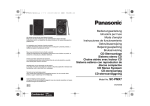
1
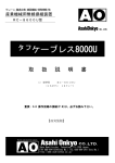
DEUTSCH
ENGLISH
MC-D207U
INSTRUCTIONS
For Customer Use:
Enter below the Model No. and Serial
No. which are located at the top of the
unit. Retain this information for future
reference.
Model No. MC-D207U
Serial No.
This instruction manual has been manufactured from 100% recycled paper.
LST0038-001B
FRANÇAIS
DVD-ROM DRIVE
Thank you for purchasing the JVC MC-D207U DVD-ROM DRIVE.
Before you start operating this unit, please read the instructions carefully in order to obtain the best possible performance.
1. DANGER: Invisivle laser radiation will occur when the unit
is open with a failed or defeated interlock.
2. CAUTION: Do not open the top cover. There are no user
serviceable parts inside the unit; leave all servicing to qualified service personnel.
2
䡵 ROM Replacement
When this drive is mounted in the MC-1200U/1600U or MC-2200U/2600U CD-ROM Library, certain serial numbers may
require to replace the ROM.
Read the section “ROM REPLACEMENT IN THE CD-ROM LIBRARY” on page 6 for the first time.
ACCESSORIES AND DOCUMENTATION
Accessories
Drive locking screw (M3 with washer) ......................... 2 (including one spare)
Documentation
Instructions .............................................................. 1
INSTALLATION
䡵 Please refer to the instruction manual of your Library for more information about the CD-ROM or CD/DVD Library.
1. How to Open the Door of the JVC Library
䡵 In order to open the door, please also refer to the section
“HOW TO OPEN THE DOOR DURING OPERATION” in the instructions for the JVC CD-ROM or CD/DVD Library.
1. Select the [DOOR OPEN MODE] on the MENU screen of the
LCD display section.
2. Press and hold the “SELECT” switch for five seconds.
3. Turn off the power of the JVC Library when the [YOU MAY OPEN
THE DOOR] or [THE DOOR CAN BE OPENED] message is
displayed on the LCD display section.
4. Insert the key in the key cylinder located at the center of the
door and turn it 90 degrees counterclockwise to unlock and open
the door.
䡵 Before you start installing the DVD-ROM Drive, be sure to
turn off the power of the host computer, all peripheral devices and the Library.
Drive locking section
Drive locking screw
mounting hole
• Figure shows the MC-1200U/E
Drive locking section
Drive locking screw
mounting hole
• Figure shows the MC-2200U
or MC-8200U
Drive locking screw
mounting hole
Drive locking section
• Figure shows the MC-2100U
or MC-8100U
3
ENGLISH
● This unit is a DVD-ROM drive with a 7x speed capability. It especially designed for the JVC CD-ROM Library or CD/DVD
Library. It is not compatible with the MC-7000 series “DVD-RAM Library”.
● The MC-D207U cannot be operated separately.
● A DVD videodisk playback is not possible with the MC-D207U.
INSTALLATION
2. How to Open the Drive Storage Cover
䡵 Please also refer to the corresponding sections in the
Library instructions.
1. Remove the screws from the drive section cover,
which is located at the rear of the Library.
2. Remove the drive storage cover.
Drive No.6
• Figure shows the MC-2200U
or MC-8200U
Drive No.5
Drive No.4
Drive storage
section
Drive No.3
Drive No.2
Drive No.1
Drive storage cover
Screws
• Figure shows the MC-2100U
or MC-8100U
Drive storage
section
Drive storage
section
Drive No.6
Drive No.5
Drive storage
section
Drive No.4
Drive storage
cover
Drive No.3
Drive No.4
Drive No.3
Drive No.2
Drive No.1
Screws
Screws
Drive No.2
Drive No.1
Screws
To be reused when
refitting the cover later.
• Figure shows the MC-1200U/E
Drive storage
cover
3. How to Determine the Installation Position of the DVD-ROM Drive
1. Install drive from the No.1 to No.6 slot in that order without skipping.
䡵 Starting installation from the lowest No.1 slot will simplify future installation work.
Drive storage section
4. How to Install the DVD-ROM Drive
Sensor slit
•Beware of damage
1. Insert the drive from the rear of the JVC CD-ROM or CD/DVD Library.
䡵 Pay attention not to damage the sensor slit.
䡵 Always insert the DVD-ROM Drive correctly.
䡵 Check that cables connected on the rear of the unit are not caught
or pinched when inserting the DVD-ROM Drive.
2. Insert the DVD-ROM Drive slowly until the screw installation hole
located on the side of the DVD-ROM Drive and the screw installation
hole located on the drive locking section are aligned.
3. Lock the DVD-ROM Drive in place by using the drive locking screw
on the door panel side of the drive.
䡵 Tighten the screw firmly.
䡵 If the drive locking screw is loose, the drive and/or CD-ROM, CD/
DVD Library could suffer damage.
Drive locking section
Drive locking
screw
4
INSTALLATION
5. How To Connect Cables To The DVD-ROM Drive
䡵 Connect to the drive the power supply cable and control cable which extend from the side of the DVD-ROM drive
installation slot.
䡵 With the MC-2100U and the MC-8100U models be sure to connect a control cable with the same component No., as
the drive bay No., otherwise proper operation may not be possible.
䡵 Insert all connectors firmly.
Rear section of the DVD-ROM Drive
Control cable
Dip switches
14p
Slide switch
W
N
4p
SCSI cable
Power supply cable
Connection example of a SCSI cable
Internal SCSI ribbon cable
• Up to six drives can be connected normally.
(But only four drives in the case of the MC-2100U
and the MC-8100U)
(Terminate here)
DVD-ROM Drive
SCSI connector
DVD-ROM Drive
OUT 2
IN 2
OUT 1
DVD-ROM Drive
Library SCSI board
IN
1
Connect an active terminator.
To be connected with host
computer's SCSI host adapter
䡵 SCSI cables should be connected as a daisy chain connection. Each connector may be connected to the drive
positions as illustrated in the diagram.
䡵 Terminate the physical end of the SCSI bus. To use the built-in drive terminator, read 6 -1.
䡵 It is recommended to use an external terminator to improve the stability of the SCSI bus communications.
6. How To Set The Dip and Slide Switches
䡵 Always turn OFF the power of Library when you set the dip switch modes.
TERM
ID 2
ID 1
ID 0
DIP switch
1
2
3
4
Slide switch
W
N
ON
(Factory setting)
OFF
1. TERM : This selects the use of the built-in terminator.
䡵 To use the built-in drive terminator, set the TERM of the drive to ON and the TERM of other drives to OFF.
䡵 When not using the built-in terminator, attach an active SCSI terminator to the OUT side of the SCSI connector.
In this case, set the TERM of all built-in drives to OFF.
5
ENGLISH
1. Connect the power supply cable, control cable and SCSI cable to the connectors at the rear of the DVD-ROM Drive.
INSTALLATION
2. ID2 - ID0 : This sets the SCSI ID No. on the drives.
Switch
SCSI ID
No.
ID2
ID1
ID0
0
OFF
OFF
OFF
1
OFF
OFF
ON
2
OFF
ON
OFF
3
OFF
ON
ON
4
ON
OFF
OFF
5
ON
OFF
ON
6
ON
ON
OFF
7
ON
ON
ON
Remarks
Default factory setting
䡵 Set the SCSI ID No. between 0 - 7 using only an ID No. that is not being used by other SCSI devices.
䡵 For the details on default factory settings, please refer to the section “SCSI ID No. SETTING” of the instructions for the
JVC CD-ROM or CD/DVD Library.
3. Set the slide switch.
䡵 Be sure to set the slide switch to N for use. (The position W is provided for service use only.)
7. How To Refit The Drive Storage Cover
䡵 Always refit the drive storage cover before switching ON the JVC CD-ROM or CD/DVD Library.
1. Fasten the cover with the screws that were removed in the procedure ( 2 -1).
8. How To Close And Lock The Door Of The JVC CD-ROM or CD/DVD Library
䡵 Always close and lock the door before switching ON the JVC CD-ROM or CD/DVD Library.
1. Close the door and lock the key cylinder.
2. Turn the power switch ON.
䡵 Before you add, remove or replace drives, and/or change the SCSI ID No., turn OFF the power of the host computer.
Remember to turn it ON again after completing the necessary operations.
9. Automatic Drive Detection Mode
䡵 Please also refer to the corresponding sections in the CD/DVD Library instructions.
䡵 If using the CD/DVD Library MC-8100U/8200U/8600U, be sure to execute the auto drive detection mode after
installing, adding, exchanging or removing drives, to prevent any malfunction.
1. While holding the “8” key on the control panel, turn on the power of the Library.
2. When the LCD display shows “DRIVE DETECTION COMPLETED”, turn off the power of the Library.
3. Turn the Library on again.
6
ROM REPLACEMENT IN THE CD-ROM LIBRARY
If the DVD-ROM drive is being mounted in a MC-2200U/2200PU/2600U/2600PU or MC-1200U/1600U CD-ROM Library and
does not meet the following conditions, the ROM is required to be replaced in the Library.
Please consult your dealer or nearest JVC-authorized service agent for ROM replacement.
䡵 The library already has a MC-D207U mounted within the unit.
䡵 The library already has a MC-D104U or a MC-R18U drive mounted within the unit.
ENGLISH
䡵 The library is a MC-2200U/2200PU/2600U/2600PU CD-ROM Library and has the last four digits of the serial number as
follows.
• MC-2200U: 0092 or after. • MC-2200PU: 0081 or after. • MC-2600U: 0387 or after. • MC-2600PU: 0061 or after.
䡵 For the ROM replacement method, please consult your dealer or nearest JVC-authorized service agent.
SPECIFICATIONS
Applicable discs
(Playback only)
: CD, CD-ROM Mode-1, CD-ROM Mode-2 (XA, CD-I, Photo-CD, Video CD) and CD-R/RW written in accordance with YELLOW BOOK, RED BOOK, GREEN BOOK and ORANGE BOOK regulations may be applicable.
DVD-ROM (Single layer: 4.7 GB/single-sided, double layer: 8.5 GB/single-sided)
DVD-R (4.7 GB or 3.95 GB, disc at once)
DVD-RAM (Ver. 2.1: single-sided 4.7 GB or double-sided 9.4 GB)
DVD-RAM (Ver. 1.0: single-sided 2.6 GB)
* Note 1: The following formatted media may not perform satisfactorily depending on the write conditions:
CD-R, CD-RW, DVD-R and DVD-RAM.
* Note 2: In order to prevent problems when using the DVD-RAM, a system that has the two features described below should be adopted. Please inquire about details for establishing this system at your
dealer or the nearest JVC-authorized service agent.
• The feature that allows the disc to be re-loaded to the disc-drive a second time. The machine
may recognize a disc after having failed to recognize it at the first loading.
• The feature that permits the timeout period for disc recognition to be set.
* Note 3: Only the discs with a diameter of 120 mm are applicable.
Interface
: SCSI-2
Data transfer speed
: Sustained (When the host adapter is set to the maximum sync transfer rate of 20 Mbytes/s)
CD-ROM:
Approx. 6 Mbytes/s max. (40X max., CAV)
DVD-ROM (Single layer):
Approx. 10 Mbytes/s max. (7X max., CAV)
DVD-ROM (Double Layer):
Approx. 10 Mbytes/s max. (7X max., CAV)
DVD-R (3.95 GB or 4.7 GB):
Appr ox. 3.46 Mbytes/s max. (2.3X max., CAV)
DVD-RAM (Single-sided 4.7 GB, single-sided 2.6 GB):
Approx. 2.77 Mbytes/s typ. (2X max., CAV)
Burst
05 Mbytes/s (asynchronous)
10 Mbytes/s (synchronous)
Average access time
(1/3 stroke, typ)
: DVD-ROM 135 ms
CD-ROM
125 ms
The above values were measured using JVC’s measurement method.
Buffer capacity
: 512 kbytes
Operating environment
: Temperature 5 °C to 35 °C
Humidity 10 % to 80 % (without condensation)
External dimension
: 171 mm x 47 mm x 243 mm (W x H x D)
Weight
: 1.7 kg
䡵 The specifications and appearance of this unit are subject to change without notice.
7
MC-D207U DVD-ROM DRIVE
VICTOR COMPANY OF JAPAN, LIMITED
is a registered Trademark owned by VICTOR COMPANY OF JAPAN, LTD.
is a registered Trademark in JAPAN, the U.S.A., the U.K. and many other countries.
© 2002 VICTOR COMPANY OF JAPAN, LIMITED
Printed in Japan
LST0038-001B