1
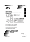
KD-DV4202/KD-DV4201
Installation/Connection Manual
Manuel d’installation/raccordement
1205DTSMDTJEIN
EN, FR
© 2005 Victor Company of Japan, Limited
GET0372-007A
[EU]
ENGLISH
FRANÇAIS
This unit is designed to operate on 12 V DC, NEGATIVE ground electrical systems. If your vehicle
does not have this system, a voltage inverter is required, which can be purchased at JVC IN-CAR
ENTERTAINMENT dealers.
Cet appareil est conçu pour fonctionner sur des sources de courant continu de 12 V à masse NEGATIVE.
Si votre véhicule n’offre pas ce type d’alimentation, il vous faut un convertisseur de tension, que vous pouvez
acheter chez un revendeur d’autoradios JVC.
WARNINGS
AVERTISSEMENTS
To prevent accidents and damage:
• DO NOT install any unit in locations where;
– it may obstruct the steering wheel and gearshift lever operations.
– it may obstruct the operation of safety devices such as air bags.
– it may obstruct visibility.
• DO NOT operate the unit while driving.
• If you need to operate the unit while driving, be sure to look ahead carefully.
• The driver must not watch the monitor while driving.
If the parking brake is not engaged, “DRIVER MUST NOT WATCH THE MONITOR WHILE
DRIVING.” appears on the monitor, and no playback picture will be shown.
– This warning appears only when the parking brake wire is connected to the parking brake
system built in the car.
Pour éviter tout accident et tout dommage:
• N’INSTALLEZ aucun élément dans les endroits suivants;
– Il peut gêner l’utilisation du volant ou du levier de vitesse.
– Il peut gêner le fonctionnement de dispositifs de sécurité tels que les coussins de sécurité.
– où il peut gêner la visibilité.
• NE manipulez pas l’appareil quand vous conduisez.
• Si vous devez commander l’appareil pendant que vous conduisez, assurez-vous de bien
regarder devant vous.
• Le conducteur ne doit pas regarder le moniteur lorsqu’il conduit.
Si le frein de stationnement n’est pas mis, “LE CONDUCTEUR NE DOIT PAS REGARDER LE
MONITEUR EN CONDUISANT.” apparaît sur le moniteur et l’image de lecture n’apparaît pas.
– Cet avertissement apparaît uniquement quand le fil du frein de stationnement est connecté
au système de frein de stationnement intégré à la voiture.
To prevent short circuits, we recommend that you disconnect the battery’s negative terminal and make all
electrical connections before installing the unit.
• Be sure to ground this unit to the car’s chassis again after installation.
Pour éviter tout court-circuit, nous vous recommandons de débrancher la borne négative de la batterie et
d’effectuer tous les raccordements électriques avant d’installer l’appareil.
• Assurez-vous de raccorder de nouveau la mise à la masse de cet appareil au châssis de la
voiture après l’installation.
Notes:
• Replace the fuse with one of the specified rating. If the fuse blows frequently, consult your JVC IN-CAR
ENTERTAINMENT dealer.
• It is recommended to connect to the speakers with maximum power of more than 45 W (both at
the rear and at the front, with an impedance of 4 Ω to 8 Ω). If the maximum power is less than
45 W, change “AMP GAIN” setting to prevent the speakers from being damaged (see page 24 of the
INSTRUCTIONS).
• To prevent short-circuit, cover the terminals of the UNUSED leads with insulating tape.
• The heat sink becomes very hot after use. Be careful not to touch it when removing this unit.
Remarques:
• Remplacer le fusible par un de la valeur précisée. Si le fusible saute souvent, consulter votre revendeur
d’autoradios JVC.
• Il est recommandé de connecter des enceintes avec une puissance de plus de 45 W (les enceintes arrière
et les enceintes avant, avec une impédance comprise entre 4 Ω et 8 Ω). Si la puissance maximum est
inférieure à 45 W, changez “AMP GAIN” pour éviter d’endommager vos enceintes (voir page 24 du
MANUAL D’INSTRUCTIONS).
• Pour éviter les court-circuits, couvrir les bornes des fils qui ne sont PAS UTILISÉS avec de la bande
isolante.
• Le dissipateur de chaleur devient très chaud après usage. Faire attention de ne pas le toucher en retirant
cet appareil.
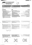
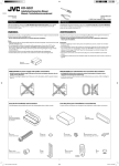
Heat sink
Dissipateur de chaleur
PRECAUTIONS on power supply and speaker connections:
PRECAUTIONS sur l’alimentation et la connexion des enceintes:
• DO NOT connect the speaker leads of the power cord to the car battery; otherwise, the unit
will be seriously damaged.
• BEFORE connecting the speaker leads of the power cord to the speakers, check the speaker wiring in
your car.
• NE CONNECTEZ PAS les fils d’enceintes du cordon d’alimentation à la batterie; sinon,
l’appareil serait sérieusement endommagé.
• AVANT de connecter les fils d’enceintes du cordon d’alimentation aux enceintes, vérifiez le câblage des
enceintes de votre voiture.
About sounds reproduced through the rear terminals
À propos des sons reproduits par les prises arrière
• Through the analog terminals (Speaker out/LINE OUT):
2-channel signal is emitted.
When playing a multi-channel encoded disc, multi-channel signals are downmixed. (AUDIO—
DOWN MIX: see page 26 of the INSTRUCTIONS.)
• Par les prises analogiques (Sortie des enceintes/LINE OUT):
Un signal à 2 canaux est sorti.
Lors de la lecture d’un disque codé multicanaux, les signaux multicanaux sont sous mixés. (AUDIO—
MIXAGE DEMULTIPLICATION: voir page 26 du MANUAL D’INSTRUCTIONS).
• Through DIGITAL OUT (optical):
Digital signals (Linear PCM, Dolby Digital*1, DTS*2, MPEG Audio) are emitted through this terminal.
(For more details, see page 26 of the INSTRUCTIONS.)
To reproduce multi-channel sounds such as Dolby Digital and DTS, connect an amplifier or a decoder
compatible with these multi-channel sources to this terminal, and set “DIGITAL AUDIO OUTPUT”
correctly. (See page 26 of the INSTRUCTIONS.)
• Par la sortie DIGITAL OUT (optique):
Les signaux numériques (Linear PCM, Dolby Digital *1, DTS *2, MPEG Audio) sont sortis par cette
prise. (Pour plus de détails, voir page 26 du MANUAL D’INSTRUCTIONS).
Pour reproduire les sons multicanaux, Dolby Digital ou DTS par exemple, connectez à cette prise un
amplificateur ou un décodeur compatible avec ces sources multicanaux, et réglez “SORTIE AUDIO
NUM.” correctement. (Voir page 26 du MANUAL D’INSTRUCTIONS).
*1 Manufactured under license from Dolby Laboratories. Dolby and the double-D symbol are trademarks of Dolby
*1 Fabriqué sous licence de Dolby Laboratories. Le terme Dolby et le sigle double D sont des marques commerciales de
Laboratories.
*2 “DTS” and “DTS 2.0 + Digital Out” are trademarks of Digital Theater Systems, Inc.
*2 “DTS” et “DTS 2.0 + Digital Out” sont des marques de commerce de Digital Theater Systems, Inc.
Dolby Laboratories.
EN CAS DE DIFFICULTES
TROUBLESHOOTING
•
*
•
*
•
*
•
*
*
•
*
•
*
*
•
*
•
*
•
*
•
*
•
*
*
•
*
•
*
*
•
*
The fuse blows.
Are the red and black leads connected correctly?
Power cannot be turned on.
Is the yellow lead connected?
No sound from the speakers.
Is the speaker output lead short-circuited?
Sound is distorted.
Is the speaker output lead grounded?
Are the “–” terminals of L and R speakers grounded in common?
Noise interfere with sounds.
Is the rear ground terminal connected to the car’s chassis using shorter and thicker cords?
Unit becomes hot.
Is the speaker output lead grounded?
Are the “–” terminals of L and R speakers grounded in common?
This unit does not work at all.
Have you reset your unit?
Le fusible saute.
Les fils rouge et noir sont-ils racordés correctement?
L’appareil ne peut pas être mise sous tension.
Le fil jaune est-elle raccordée?
Pas de son des enceintes.
Le fil de sortie d’enceinte est-il court-circuité?
Le son est déformé.
Le fil de sortie d’enceinte est-il à la masse?
Les bornes “–” des enceintes gauche et droit sont-elles mises ensemble à la masse?
Interférence avec les sons.
La prise arrière de mise à la terre est-elle connectée au châssis de la voiture avec un cordon court et épais?
L’appareil devient chaud.
Le fil de sortie d’enceinte est-il à la masse?
Les bornes “–” des enceintes gauche et droit sont-elles mises ensemble à la masse?
Cet appareil ne fonctionne pas du tout.
Avez-vous réinitialisé votre appareil?
1
Instal1-2_DV4202_007A_f.indd 1
12/15/05 9:18:26 AM
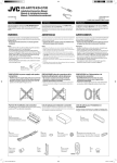
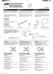
Parts list for installation and connection
Liste des pièces pour l’installation et raccordement
If any item is missing, consult your JVC IN-CAR ENTERTAINMENT dealer immediately.
Si quelque chose manquait, consultez votre revendeur autoradio JVC immédiatement.
A/B
Hard case/Control panel
Etui de transport/Panneau
de commande
C
Sleeve
Manchon
D
Trim plate
Plaque d’assemblage
E
Power cord
Cordon d’alimentation
F
Crimp connector
Cosse à sertir
G
Washer (ø5)
Rondelle (ø5)
H
Lock nut (M5)
Ecrou d’arrêt (M5)
I
Mounting bolt (M5 × 20 mm)
Boulon de montage (M5 × 20 mm)
J
Rubber cushion
Amortisseur en
caoutchouc
K
Handles
Poignées
L
Remote controller
Télécommade
M
Battery
Pile
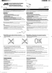
INSTALLATION (IN-DASH MOUNTING)
INSTALLATION (MONTAGE DANS LE TABLEAU DE BORD)
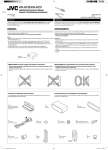
The following illustration shows a typical installation. If you have any questions or require information
regarding installation kits, consult your JVC IN-CAR ENTERTAINMENT dealer or a company supplying
kits.
• If you are not sure how to install this unit correctly, have it installed by a qualified technician.
L’illustration suivante est un exemple d’installation typique. Si vous avez des questions ou avez besoin
d’information sur des kits d’installation, consulter votre revendeur d’autoradios JVC ou une compagnie
d’approvisionnement.
• Si l’on n’est pas sûr de pouvoir installer correctement cet appareil, le faire installer par un technicien
qualifié.
Do the required electrical
connections.
Réalisez les connexions électriques.
*3 When you stand the unit, be
careful not to damage the fuse on
the rear.
*3 Lorsque vous mettez l’appareil à la
verticale, faire attention de ne pas
endommager le fusible situé sur
l’arrière.
When using the optional stay / Lors de l’utilisation du
hauban en option
Stay (option)
Hauban (en option)
Fire wall
Cloison
Bend the appropriate tabs to hold
the sleeve firmly in place.
Tordez les languettes appropriées
pour maintenir le manchon en place.
When installing the unit without using the sleeve / Lors de l’installation de l’appareil
scans utiliser de manchon
In a Toyota car for example, first remove the car radio and install the unit in its place.
Dans une voiture Toyota, par exemple, retirez d’abord l’autoradio et installez l’appareil à la place.
Flat type screws (M5 × 8 mm) *4
Vis à tête plate (M5 × 8 mm) *4
*4 Not supplied for this unit.
*4 Non fourni avec cet appareil.
Bracket *4
Support *4
Dashboard
Tableau de bord
Screw (option)
Vis (en option)
Flat type screws (M5 × 8 mm) *4
Vis à tête plate (M5 × 8 mm) *4
Pocket
Poche
Note
Install the unit at an angle of less than 30˚.
Installez l’appareil avec un angle de moins de 30˚.
Remarque
Bracket *4
Support *4
: When installing the unit on the mounting bracket, make sure to use the 8 mm-long screws. If longer
screws are used, they could damage the unit.
: Lors de l’installation de l’appareil sur le support de montage, s’assurer d’utiliser des vis d’une longueur
de 8 mm. Si des vis plus longues sont utilisées, elles peuvent endommager l’appareil.
Removing the unit
Retrait de l’appareil
Before removing the unit, release the rear section.
Avant de retirer l’appareil, libérer la section arrière.
Insert the two handles, then pull them as illustrated
so that the unit can be removed.
Insérez les deux poignées, puis tirez de la façon
illustrée de façon à retirer l’appareil.
2
Instal1-2_DV4202_007A_f.indd 2
12/15/05 9:18:31 AM
ENGLISH
FRANÇAIS
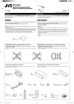
ELECTRICAL CONNECTIONS
RACCORDEMENTS ELECTRIQUES
A If your car is equipped with the ISO connector / Si For some VW/Audi or Opel (Vauxhall) automobile / Pour certaine voiture VW/Audi ou
Opel (Vauxhall)
votre voiture est équippée d’un connecteur ISO
You may need to modify the wiring of the supplied power cord as illustrated.
• Contact your authorized car dealer before installing this unit.
Vous aurrez peut-être besoin de modifier le câblage du cordon d’alimentation fourni comme montré sur l’illustration.
• Contactez votre revendeur automobile autorisé avant d’installer l’appareil.
• Connect the ISO connectors as illustrated.
• Connectez les connecteurs ISO comme montré sur l’illustration.
From the car body
De la carrosserie de la voiture
ISO connector of the supplied power cord
Connecteur ISO pour le cordon d’alimentation
fourni
Original wiring / Câblage original
Modified wiring 1 / Câblage modifié 1
ISO connector
Connecteur ISO
Use modified wiring 2 if the unit does not turn on.
Utilisez le câblage modifié 2 si l’appareil ne se met pas sous tension.
View from the lead side
Vue à partir du côté des fils
Modified wiring 2 / Câblage modifié 2
R: Red
Rouge
Y: Yellow
Jaune
B Connections without using the ISO connectors / Connexions sans l’utilisation des connecteurs ISO
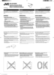
Before connecting: Check the wiring in the vehicle carefully. Incorrect connection may cause serious
damage to this unit.
The leads of the power cord and those of the connector from the car body may be different in color.
1 Cut the ISO connector.
2 Connect the colored leads of the power cord in the order specified in the illustration below.
3 Connect the aerial cord.
4 Finally connect the wiring harness to the unit.
VIDEO OUT
(see diagram /
voir le diagramme
Avant de commencer la connexion: Vérifiez attentivement le câblage du véhicule. Une connexion
incorrecte peut endommager sérieusement l’appareil.
Le fil du cordon d’alimentation et ceux des connecteurs du châssis de la voiture peuvent être différents en
couleur.
1 Coupez le connecteur ISO.
2 Connectez les fils colorés du cordon d’alimentation dans l’ordre spécifié sur l’illustration ci-dessous.
3 Connectez le cordon d’antenne.
4 Finalement, connectez le faisceau de fils à l’appareil.
To steering wheel remote controller (see diagram )
Pour la télécommande de volant (voir le diagramme )
Rear ground terminal
Borne arrière de masse
)
To external components (see diagram )
Aux appareils extérieurs (voir le diagramme
)
15 A fuse
Fusible 15 A
Line out (see diagram
Sortie de ligne (voir le
diagramme )
*1 Not supplied for this unit.
*1 Non fourni avec cet appareil.
)
Black
Noir
Aerial connector
Connecteur d’antenne
DIGITAL OUT
(see diagram /
voir le diagramme
To metallic body or chassis of the car
Vers corps métallique ou châssis de la voiture
Yellow *2
Jaune *2
)
To a live terminal in the fuse block connecting to the car battery (by passing the
ignition switch) (constant 12 V)
A une borne sous tension du porte-fusible connectée à la batterie de la voiture (en
dérivant l’interrupteur d’allumage) (12 V constant)
Red
Rouge
To an accessory terminal in the fuse block
Vers borne accessoire du porte-fusible
Fuse block
Porte-fusible
Blue with white stripe
Bleu avec bande blanche
installation, this lead must be connected, otherwise power
cannot be turned on.
*2 Pour vérifier le fonctionnement de cet appareil avant
installation, ce fil doit être raccordé, sinon l’appareil ne peut
pas être mis sous tension.
White with black stripe
Blanc avec bande noire
White
Blanc
To the remote lead of other equipment or power aerial if any (200 mA max.)
Au fil de télécommande de l’autre appareil ou à l’antenne automatique s’il y en a une (200 mA max.)
Brown
Marron
*2 Before checking the operation of this unit prior to
Gray with black stripe
Gris avec bande noire
Left speaker (front)
Enceinte gauche (avant)
Ignition switch
Interrupteur d’allumage
To cellular phone system
À un système de téléphone cellulaire
Light green
Vert clair
To parking brake, metallic body or chassis of the car
Au frein de stationnement, corps métallique ou châssis du véhicule
Gray
Gris
Green with black stripe
Vert avec bande noire
Right speaker (front)
Enceinte droit (avant)
Green
Vert
Purple with black stripe
Violet avec bande noire
Left speaker (rear)
Enceinte gauche (arrière)
Purple
Violet
Right speaker (rear)
Enceinte droit (arrière)
D Connecting the crimp connector / Connexion de la cosse sertie
C Connecting the parking brake wire / Connexion du cordon de frein
de stationnement
When installing the monitor in a location where it can be seen by the driver
Connect the parking brake wire to the parking brake system built in the car.
Lorsqu’on installe le moniteur à un emplacement où il peut être vu du conducteur
Connectez le fil de frein de stationnement au système de frein de stationnement.
Wire connecting the battery and the parking brake switch.
Fil connectant la batterie et l’interrupteur de frein de stationnement.
Attach the parking brake wire to this point.
Attachez le fil du frein de stationnement ici.
Parking brake wire (light
green)
Fil du frein de
stationnement (vert clair)
Parking brake
Frein de stationnement
Parking brake switch (inside the car)
Commutateur de frein de
stationnement (intérieur de la voiture)
To metallic body or
chassis of the car
Vers corps métallique ou
châssis de la voiture
Pinch the crimp firmly.
Pincez la cosse à sertir fermement.
When installing the monitor in a location where it cannot be seen by the driver
Connect the parking brake wire to metallic body or chassis or the car.
Lorsqu’on installe le moniteur à un emplacement où il ne peut pas être vu du conducteur
Connectez le fil du frein de stationnement au corps métallique ou châssis du véhicule.
Parking brake wire (light green)
Fil du frein de stationnement (vert clair)
Contact the metallic part of the crimp to the wires inside.
Mettez en contact la partie métallique de la cosse à sertir et
des fils intérieurs.
*3 Not supplied for this unit.
*3 Non fourni avec cet appareil.
3
Instal3-4_DV4202_007A_f.indd 3
12/15/05 9:18:59 AM
E Required connections for DVD playback / Connexions requises pour la lecture de DVD
Video cord (not supplied)
Cordon vidéo (non fourni)
KV-MR9010
9-INCH WIDESCREEN MONITOR
(not supplied)
MONITEUR À ÉCRAN LARGE DE
9 POUCES (non fourni)
Digital optical cable (not supplied)
Câble optique numérique (non fourni)
DIGITAL OUT
See “About sounds reproduced
through the rear terminals.”
Référez-vous “À propos des sons
reproduits par les prises arrière”.
Audio/video control amplifier or the decoder compatible with the multichannel
digital sources
Amplificateur de commande audio/vidéo ou décodeur compatible avec les sources
numériques multicanaux
F Connecting to the steering wheel remote controller / Connexion de la télécommande de volant
If your car is equipped with the steering wheel remote controller, you can operate this unit using the
controller. To do it, a JVC’s OE remote adapter (not supplied) which matches with your car is required.
Consult your JVC IN-CAR ENTERTAINMENT dealer for details.
Steering wheel remote input
Entrée de la télécommande de volant
Si votre voiture est munie d’une télécommande de volant, vous pouvez commander cet autoradio en
utilisant la télécommande. Pour le faire, un adaptateur pour télécommande au volant JVC (non fourni)
correspondant à votre voiture est nécessaire. Consultez votre revendeur d’autoradio JVC pour les détails.
OE remote adapter (not supplied)
Adaptateur pour télécommande au volant (non fourni)
Steering wheel remote controller (equipped in the car)
Télécommande de volant (installée dans la voiture)
G Connecting the external amplifier / Connexion d’un amplificateur extérieur
Vous pouvez connecter un amplificateur pour améliorer votre système autoradio.
• Connectez le fil de commande à distance (bleu avec bande blanche) au fil de commande à distance de
l’autre appareil de façon qu’il puisse être commandé via cet appareil.
• Déconnectez les enceintes de cet appareil et connectez-les à l’amplificateur. Laissez les fils
d’enceintes de cet appareil inutilisés.
You can connect an amplifier to upgrade your car stereo system.
• Connect the remote lead (blue with white stripe) to the remote lead of the other equipment so that it
can be controlled through this unit.
• Disconnect the speakers from this unit, connect them to the amplifier. Leave the speaker
leads of this unit unused.
Remote lead
Fil d’alimentation à distance
Y-connector (not supplied for this unit)
Connecteur Y (non fourni avec cet appareil)
Remote lead (Blue with white stripe)
Fil d’alimentation à distance (Bleu avec bande blanche)
Rear speakers
Enceintes arrière
To the remote lead of other equipment or power aerial if any
Au fil de télécommande de l’autre appareil ou à l’antenne
automatique s’il y en a une
JVC Amplifier
JVC Amplificateur
Rear speakers
Enceintes arrière
*4
Firmly attach the ground wire to the metallic body or to the chasis of the car—to the place not
coated with paint (if coated with paint, remove the paint before attaching the wire). Failure to do
so may cause damage to the unit.
*4 Attachez solidement le fil de mise à la masse au châssis métallique de la voiture—à un endroit qui
n’est pas recouvert de peinture (s’il est recouvert de peinture, enlevez d’abord la peinture avant
d’attacher le fil). L’appareil peut être endommagé si cela n’est pas fait correctement.
Front speakers (see diagram )
Enceintes avant (voir le diagramme
)
*6 Cut the rear speaker leads of the car’s ISO connector and connect them to
the amplifier.
*6 Coupez les fils des enceintes arrière du connecteur ISO de la voiture et
*5 Signal cord (not supplied for this unit)
*5 Cordon de signal (non fourni avec cet appareil)
connectez-les à l’amplificateur.
H Connecting the external components / Connexion des appareils extérieurs
CD changer, DAB tuner, Apple iPod®, or JVC D. player / Changeur de CD, tuner DAB, iPod‚ Apple® ou lecteur D. JVC
• Set “CHANGER” for the external input setting (See page 24 of the INSTRUCTIONS.) / Choisissez “CHANGER” pour le réglage de l’entrée extérieure (Voir page 24 du MANUAL D’INSTRUCTIONS.)
You can connect these components in series as illustrated below. The iPod*7 or D. player can be connected using an interface adapter (not supplied)—KS-PD100 (for iPod) or KS-PD500 (for D. player).
Vous pouvez connecter ces appareils en série comme montrée sur l’illustration. Le iPod*7 ou le lecteur D. peut être connecté en utilisant un adaptateur d’interface (non fourni)—KS-PD100 (pour iPod) ou KS-PD500
(pour le lecteur D.).
Apple iPod (separately purchased)
iPod Apple (vendu séparément)
or
ou
JVC D. player (separately
purchased)
Lecteur D. JVC (vendu séparément)
JVC CD changer
Changeur de CD JVC
JVC DAB tuner
Tuner DAB JVC
Apple iPod (separately purchased)
iPod Apple (vendu séparément)
CAUTION / PRECAUTION:
Before connecting the external components,
make sure that the unit is turned off.
Avant de connecter les appareils extérieurs,
assurez-vous que l’appareil est hors tension.
*7 iPod is a trademark of Apple Computer, Inc.,
registered in the U.S. and other countries.
*7 iPod est une marque de commerce d’Apple
Computer, Inc., enregistrée aux États-Unis et
dans les autres pays.
or
ou
JVC DAB tuner
Tuner DAB JVC
or
ou
JVC D. player (separately
purchased)
Lecteur D. JVC (vendu séparément)
JVC CD changer
Changeur de CD JVC
*8 Connecting cord supplied for your CD
changer or DAB tuner
*8 Cordon de connexion fourni avec votre
changeur de CD ou tuner DAB
Other external component / Autre appareil extérieur
• Set “EXT IN” for the external input setting (See page 24 of the INSTRUCTIONS.) / Choisissez “EXT IN” pour le réglage de l’entrée extérieure (Voir page 24 du MANUAL D’INSTRUCTIONS.)
External component
Appareil extérieur
CD changer jack
Prise du changeur de CD
External component
Appareil extérieur
*9 Line Input Adapter KS-U57 (not supplied for this unit)
*9 Adaptateur d’entrée de ligne KS-U57 (non fourni avec cet appareil)
*10 AUX Input Adapter KS-U58 (not supplied for this unit)
*10 Adaptateur d’entrée AUX KS-U58 (non fourni avec cet appareil)
3.5 mm stereo mini plug
Mini fiche stéréo de 3,5 mm
4
Instal3-4_DV4202_007A_f.indd 4
12/21/05 10:18:03 AM