1
HV- 29LPZ
SERVICE MANUAL
COLOUR TELEVISION
HV-29LPZ
HV-29LPZ/HK
HV-29LPZ/-A
HV-29LPZ/EE
BASIC CHASSIS
MF
CONTENTS
!
!
!
!
!
1
SPECIFICATIONS ・・・・・・・・・・・・・・・・・・・・ 2
SAFETY PRECAUTIONS ・・・・・・・・・・・・・・3
・・・・・・・・・・・・・・
MAIN DIFFERENCE LIST ・・・・・・・・・・・・・・4
・・・・・・・・・・・・・・
FEATURES・・・・・・・・・・・・・・・・・・・・・・・・・・
・・・・・・・・・・・・・・・・・・・・・・・・・・ 4
FUNCTIONS ・・・・・・・・・・・・・・・・・・・・・・・・・ 6
!
!
!
★
★
SPECIFIC SERVICE INSTRUCTIONS ・・・・ 8
SERVICE ADJUSTMENTS・・・・・・・・・・・・
・・・・・・・・・・・・ 14
PARTS LIST ・・・・・・・・・・・・・・・・・・・・・・・ 37
OPERATING INSTRUCTIONS
STANDARD CIRCUIT DIAGRAM ・・・・・・・ 2-1
CO PYRIGHT © 2002 VICTOR COMPANY OF JAPAN, LTD.
No.52012
Jun. 2002
HV- 29LPZ
SPECIFICATIONS
Item
Content
Dimensions ( W×
×H×
×D )
73.2cm×58.7c m× 51.8cm
Mass
48.0kg
TV RF System
B/G, I, D/K, K1, M
Colour System
PAL / SECAM / NTSC 3.58 / NTSC 4.43
Stereo System
A2 (B/G) / NICAM (B/G, I, D/K, K1)
Teletext System
Fastext (UK system) *
WST(world s tandard Texst)
[ * Without TEXT mode : HV-29LPZ/HK ]
VL
46.25MHz ~ 168.25MHz
Receiving
Frequency
VH
175.25MHz ~ 463.25MHz
UHF
CATV
471.25MHz ~ 863.25MHz
Intermediate
Frequency
VIF
Mid (X~Z+2, S1~S10), Super (S11 ~S20) & Hyper (S21~S41)
38.0MHz
SIF
32.5MHz(5.5MHz) / 32.0MHz(6.0MHz) / 3.15MHz(6.5MHz) / 33.5MHz (4.5MHz)
PAL
4.43MHz
SECAM
4.40625MHz / 4.25MHz
NT SC
3.58MHz / 4.43MHz
Colour Sub Carr ier
Frequency
Power Input
AC 110V~240V , 50/60Hz
Power Consumption
Max 254W / Avg. 170W
Aerial Input Term
75 Ωunbalanc ed, Coaxial
Pictur e Tube
29”(68c m) measured diagonally
High Voltage
+1.0kV
31.5kV -1.5kV (At zero beam current )
Au dio Power Output
20W + 20W
Speaker
φ10cm Round type×2 / φ3.5cm Round type×2
Input
Terminal
Video
1Vp-p 75 Ω
Au dio (L/R)
500mVrms(-4dBs), High Impedance
S / Video
Comp onent Cb/Cr
Y : 1V(p-p) Positive (Negative s ync provided) 75 Ω
C : 0.286V(p-p) (burst signal), 75Ω
Y : 1V(p-p), 75 Ω
Cb : B-Y 0.7V(p-p), 75Ω / Cr : R-Y 0.7V(p-p), 75Ω
Output
Video
1V(p-p) 75Ω
Terminal
Au dio (L/R)
500mVrms(-4dBs), Low Impedanc e
AV Compulink
Mono mini jack (φ3.5mm )
Headphone jack
Stereo mini jac k (φ3.5mm )
Remote Contr ol Unit
RM-C214 (AA/R06 / UM-3 , Dry cell battery×2) : HV-29LPZ / HV-29LPZ/-A / HV-29LPZ/EE
RM-C215 (AA/R06 / UM-3 , Dry cell battery×2) : HV-29LPZ/HK
Design & specifications are subject to change without notice .
2
No.52012
HV- 29LPZ
SAFETY PRECAUTIONS
1. The design of this product contains special hardware, many
circuits and components specially for safety purposes. For
continued protection, no changes should be made to the original
design unless authorized in writing by the manufacturer.
Replacement parts must be identic al to thos e used in the original
circuits. Service should be performed by qualified pers onnel
only.
2. Alterations of the design or circuitry of the products should not be
made. Any design alterations or additions will void the
manufacturer's warranty and will further relieve the manufacturer
of responsibility for personal injury or property damage resulting
therefrom.
3. Many electrical and mechanical parts in the products have
special safety-related characteristics. T hese characteristics are
often not evident from visual inspection nor can the protection
afforded by them necessarily be obtained by using replacement
components rated for higher voltage, wattage, etc. Replacement
parts whic h have these special s afety characteristics are
identified in the parts list of Servic e manual. Electrical
components having su ch features ar e identified by shading
on the schematics and by (!
! ) on the parts list in Service
manual. The us e of a substitute replacement which does not
have the same safety characteristics as the recommended
replac ement part shown in the parts list of Service manual may
cause shock, fire, or other hazards .
4. Do n't shor t between the LIVE side ground and ISOL ATED
(NEUTRAL) side ground or EARTH side ground when
repairing.
Some model's power circuit is partly different in the GND. The
differenc e of the GND is shown by the LIVE : (") side GND, the
ISOLATED(NEUTRAL) : (#) side GND and EARTH : ($) side
GND. Don't short between the LIVE side GND and
ISOLATED(NEUTRAL) side GND or EARTH side GND and
never measure with a measuring apparatus (oscilloscope etc.)
the LIVE side GND and ISOLATED(NEUTRAL) side GND or
EARTH side GND at the s ame time.
If above note will not be kept, a fuse or any parts will be broken.
5. If any repair has been made to the chassis, it is recommended
that the B1 setting should be checked or adjusted (See
ADJUSTMENT OF B1 POWER SUPPLY).
9. Isolation Check
(Safety for Electrical Shock Hazard)
After re-ass embling the product, always perform an isolation
check on the exposed metal parts of the cabinet (antenna
terminals, video/audio input and output terminals, Control knobs,
metal cabinet, screwheads, earphone jack, control shafts, etc.)
to be sure the product is s afe to operate without danger of
electrical shoc k.
(1) Dielectric Strength Test
The isolation between the AC primary circuit and all metal parts
exposed to the us er, particularly any expos ed metal part having a
return path to the chass is should withs tand a voltage of 3000V
AC (r.m.s.) for a period of one sec ond.
(. . . . Withstand a voltage of 1100V AC (r.m.s.) to an applianc e
rated up to 120V, and 3000V AC (r.m.s.) to an appliance rated
200V or more, for a period of one second.)
This method of test requires a test equipment not generally found
in the servic e trade.
(2) Leakage Current Check
Plug the AC line c ord directly into the AC outlet (do not use a line
isolation transformer during this check.). Using a " Leakage
Current Tester", measure the leakage current from each exposed
metal part of the cabinet, particularly any expos ed metal part
having a return path to the chassis , to a known good earth
ground (water pipe, etc.). Any leakage current must not exceed
0.5mA AC (r.m.s.).
However, in tropic al area, this must not exceed 0.2mA AC
(r.m.s.).
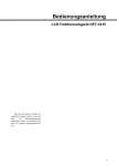
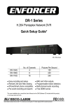
" Alternate Check Method
Plug the AC line c ord directly into the AC outlet (do not use a line
isolation transformer during this check.). Use an AC voltmeter
having 1000 ohms per volt or more sens itivity in the following
manner. Connec t a 1500Ω 10W res istor paralleled by a 0.15µF
AC-type c apacitor between an exposed metal part and a known
good earth ground (water pipe, etc.). Meas ure the AC voltage
across the res istor with the AC voltmeter. Move the resistor
connec tion to each exposed metal part, particularly any exposed
metal part having a return path to the chassis, and measure the
AC voltage ac ross the res istor. Now, reverse the plug in the AC
outlet and repeat eac h measurement. Any voltage measured
must not exc eed 0.75V AC (r.m.s.). This c orresponds to 0.5mA
AC (r.m.s.).
However, in tropical area, this must not exceed 0.3V AC ( r.m.s.).
This corresponds to 0.2mA AC (r.m.s.).
6. The high voltage applied to the picture tube must conform with
that specified in Service manual. Excessive high voltage can
cause an increase in X-Ray emission, arcing and possible
component damage, therefore operation under excessive high
voltage conditions should be k ept to a minimum, or should be
prevented. If s evere arc ing occurs, remove the AC power
immediately and determine the cause by visual inspection
(incorrect installation, cracked or melted high voltage harness,
poor soldering, etc.). To maintain the proper minimum level of
soft X-Ray emission, c omponents in the high voltage circuitry
including the picture tube must be the exact replacements or
alternatives approved by the manufacturer of the c omplete
product.
AC VOLT MET ER
(HAVING 1000 Ω/V,
OR MOR E SENSIT IVITY)
0.15μF AC-T YPE
1500 Ω 10W
PLACE T HIS PROBE
ON EACH EXPOSED
MET AL PART
GOOD EARTH GROUND
7. Do not c hec k high voltage by drawing an arc. Use a high voltage
meter or a high v oltage probe with a VTVM. Discharge the
picture tube before attempting meter connection, by c onnecting
a clip lead to the ground frame and c onnecting the other end of
the lead through a 10kΩ 2W resistor to the anode button.
8. When service is required, observe the original lead dress. Extra
prec aution should be given to assure correct lead dress in the
high voltage circuit area. W here a s hort circuit has occurred,
those components that indicate evidence of overheating should
be replaced. Always use the manufacturer's replacement
components.
No.52012
3
HV- 29LPZ
MAIN DIFFERENCE LIST
Model name
HV- 29LPZ
HV- 29LPZ /HK
HV- 29LPZ /-A
HV- 29LPZ/EE
MICOM PWB
SMF0M901A-H2
SMF0M902A-H2
SMF0M903A-H2
SMF0M904A-H2
!
POWER CORD
QMP40D0-200J5
QMPN050-200-E2
QMPR010-200-E2
QMP40D0-200J5
!
FRONT CABI.ASSY
LC11193-008B-H
LC11193-023A-H
LC11193-008B-H
!
REAR COVER
LC10763-007B-HH
LC10763-002D-H
LC10763-007B-HH
!
RATING LABEL
LC20377-001B-H
LC20377-012B-H
LC20413-002B-H
LC20377-009B-H
!
INST BOOK
LCT1215-001A-H
LCT1217-001A-H
LCT1215-001A-H
LCT1218-001A-H
!
DIGEST MANUAL
×
×
LCT1216-001A-H
×
!
CONVERSION PLUG
×
×
QAM0055-001
×
WARRANTY CARD
×
×
×
BT-54012-2
RM-C214-1C
RM-C215-1C
RM-C214-1C
!
Part n ame
REMOTE CONTROL UNIT
FEATURES
" New chassis design enable us e of an interac tive on screen
control.
" The TELETEXT SYSTEM has a built-in FASTEXT (UK s ystem),
and WST (world standard sys tem) system.
* Exc ept HV-29LPZ/HK.
" Pure FLAT CRT reproduc e fine textured.
" Digi Pure pro : Auto digi pure with motion picture c ompensation.
" Becaus e this TV unit corresponds to multiplex broadcast, users
can enjoy music programs and s porting events with live realism.
In addition, BILINGUAL programs can be heard in their original
language.
4
" Built-in ECO (ECONOMY, ECOLOGY) MODE.
In accordance with the brightness in a room, the brightness
and/or contrast of the picture can be adjusted automatic ally to
make the optimum picture which is eas y on the eye.
No. 52012
HV- 29LPZ
SYSTEM BLOCK DIAGRAM
MICOM PWB
IC 004
MEMORY
IC 001
MICRO COMPUTER
SDA 0
SCL 0
SDA 2
SCL 2
SDA 1
SCL 1
MAIN PWB
IC 701
BBE CONTROL
IC 301
DEF & RGB
PROCESSOR
IC 101
MULTI SOUND
PROCESSOR
TU0 01
TUNER
SYNC SEP PWB
100Hz PWB
IC 101
VIDEO PROCESS
&
CODEC MAIN
IC 301
SYNC SEP PWB
IC 151
VIDEO PROCESS
&
CODEC SUB
AV SW PWB
IC 101
SW
IC 201
SAMPLE RATE
CONVERTER
TU0 01
TUNER
IC 301
ENHANCE
No. 52012
5
HV- 29LPZ
FUNCTIONS
■ Front Terminal & Control
1 HEADPHONE jack
2 VIDEO-4 terminal (S-VIDEO / VIDEO / L/MONO / R)
3 MENU/OK Button
4 CHANNEL -/+ (MENU UP/DOWN) Button
5 VOLUME -/+ (MENU LEFT/RIGHT) Button
6 TV/VIDEO / EXIT Button (Input s elect)
7 SENSOR (Remote Control & ECO)
8 SPATIALIZER LAMP
9 ECO LAMP
A POWER LAMP
B POWER SW Button (MAIN POWER on and off)
■ Rear Terminal
1VIDEO-1 (INPUT) terminal (S, V, L, R)
2 VIDEO-2 (INPUT) terminal (V, L, R)
3 VIDEO-3 (INPUT) terminal (V/Y, Cb, Cr, L, R)
/ COMPONENT
4OUTPUT (AUDIO/VIDEO) terminal (V, L, R)
5 AV COMPULINK terminal
6 AERIAL socket
6
No. 52012
HV- 29LPZ
■ Remote Control Unit
1 POWER Key
(SUB POWER on and off)
2 BASS Key
(SUPER BASS function on or off)
3 SPATIALIZER Key
(Choos e a mode LIVE→MONO→OFF)
4TV/VIDEO Key
5PICTURE MODE Key
(Choos e a mode BRIGHT →STANDARD→ SOFT)
6 ZOOM Key
(Choos e a mode REGULAR→ZOOM →16:9)
7CHANNEL Key
8 -/-- Key
9 RETURN + Key
AMULTI Key
B VOLUME +/- Key
CCHANNEL +/- Key
D MUTING Key
E PIP MODE
FPIP Key
G POSITION Key
HFREEZE Key
View the MAIN picture’s frozen image as the
SUB-PICTURE.
I SUB P (PIP)+&- Key
J NEXT Key
KSWAP Key
L STROBE Key
View the MAIN-picture as 15 c onsec utive
Still image.
MDISPLAY Key
N STEREO
Ⅰ /ⅡKey
: Stereo /
: Mono
Ⅰ : Bilingual (subⅠ)
Ⅱ : Bilingual (subⅡ)
O FUNCTION Key(▲/▼&
PMENU/OK Key
Q COLOUR Key
/
)
(Choos e the appropriate colour system.)
RCOLOUR SYSTEM Key
(Choos e the appropriate colour system.)
SSOUND SYSTEM Key
(Choos e the appropriate sound system.)
UTELETEXT Key
(W ithout HV-29LPZ/HK)
No. 52012
7
HV- 29LPZ
SPECIFIC SERVICE INSTRUCTIONS
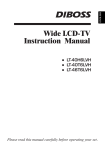
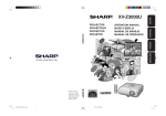
DISASSEMBLY PROCEDURE
REMOVING THE REAR COVER
CHECKING THE PW BOARD
1. Unplug the power c ord.
2. Remove the 16 screws marked ! as shown in the Fig. 1.
3. Withdraw the rear cover toward you.
To check the back side of the PW Board.
1) Pull out the chassis . (Refer to REMOVING THE CHASSIS).
2) Erect the c hassis vertically so that you c an easily check the
back side of the PW Board.
REMOVING THE AV TERMINAL BOARD
[CAUTION]
" When erec ting the chassis, be careful s o that there will be no
contacting with other PW Board.
" Before turning on power, make sure that the wire connector is
properly connec ted.
" When conducting a check with power supplied, be sure to c onfirm
that the CRT EARTH WIRE (BRAIDED ASS’Y) is connected to
the CRT SOCKET PW board.
" After removing the rear cover.
1. Remove the 5 screws marked " as shown in the Fig. 1.
2. Withdraw the AV terminal board toward you.
REMOVING THE CHASSIS
" After removing the rear cover.
1. Slightly raise the both sides of the c hassis by hand and remove
the 2 claws under the both s ides of the chas sis from the front
cabinet.
2. Withdraw the chass is backward.
(If necess ary, take off the wire clamp, connectors etc.)
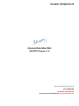
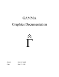
REMOVING THE DOME SPEAKER BOX / SPEAKER
" After removing the rear cover.
1. As s hown in Fig. 1, remove the 2 screws marked # , then
remove the dome speaker box.
2. Remove the 5 screws marked $ as shown in the Fig.2, then
remove the dome box.
3. Remove the 4 screws marked % as shown in the Fig.2, then
remove the HONE RING.
4. Remove the 4 screws marked & as shown in the Fig.2, then
remove the speaker.
5. Follow the same steps when removing the other hand dome
speaker box / speaker.
NOTE : When removing the screws marked # of the dome speaker
box, remove the lower side sc rew first, and then remove the
upper one.
WIRE CLAMPING AND CABLE TYING
1. Be sure to clamp the wire.
2. Never remove the c able tie used for tying the wires together.
Should it be inadvertently removed, be sure to tie the wires with
a new c able tie.
DOME SPEAKER BOX
HORN
SPEAKER
(Tweeter)
F (×4)
E
(×4)
G
( ×7)
SPEAKER
HORN
PANEL
REMOVING THE TWEETER SPEAKER
HORN RING
" After removing the rear cover.
1. Remove the 7 screws marked ' as shown in the Fig.2, then
remove the HONE PANEL.
2. Then remove the tweeter speaker screws to remove it.
DOME BOX
D
(×5)
Fig. 2
8
No.52012
HV- 29LPZ
DOME
SPEAKER BOX
FRONT CABINET
CRT
SOCKET
PWB
FRONT
CONT ROL
PWB (2/2)
C
CONT ROL
BASE
MICOM
PWB
POWER & DEF
PWB
CLAW
100Hz
PWB
AV
TERMINAL
FRONT
CONT ROL
PWB (1/2)
CONT ROL
BASE
MAIN PWB
CHASSIS
BLK
PWB
CLAW
AV SW PWB
C
B
(×5)
DOME
SPEAKER BOX
POWER CORD
REAR COVER
A (×15)
Fig. 1
No.52012
9
HV- 29LPZ
REMOVING THE CRT
∗ Replacement of the CRT should be performed by 2 or more
pers ons.
• After removing the c over, chassis etc.,
1. Putting the CRT c hange table on soft cloth, the CRT change table
should also be c overed with s uch soft cloth (shown in Fig.3).
2. While keeping the s urfac e of CRT down, mount the TV s et on the
CRT change table balanced will as shown in Fig.4.
3. Remove 4 sc rews marked by arrows with a box type screw driver
as s hown in Fig.4.
• Sinc e the cabinet will drop when screws have been removed, be
sure to support the cabinet with hands.
4. After 4 screws have been removed, put the cabinet slowly on
cloth (At this time, be carefully so as not to damage the front
surfac e of the c abinet) shown in Fig.5.
• The CRT should be ass embled according to the opposite
sequence of its dismounting steps.
∗ The CRT change table should preferably be smaller that the CRT
surfac e, and its height be about 35c m. (Fig.3)
∗ About CRT Spacer (Fig.4)
An appropriate CRT spacer should be us ed in the corresponding
CRT in acc ordance with the type of the CRT.
When a CRT is replaced, special attention should be paid to this
matter.
CRT CHANGE TABLE
APPROX.
35cm
CLOTH
Fig. 3
Fig. 4
CRT
COATING OF SILICON GREASE FOR ELECTRICAL
INSULATION ON THE CRT ANODE CAP SECTION.
•
Subsequent to replacement of the CRT and HV transformer or
repair of the anode cap, etc. by dismounting them, be sure to
coat silic on greas e for electrical insulation as shown in Fig.6.
Wipe around the anode button with clean and dry cloth. (Fig.6)
Coat silicon grease on the section around the anode button. At
this time, take care so that any silicon greas es dose not stick to
the anode button. (Fig.7)
CABINET
CRT
CHANGE TABLE
Fig. 5
★ Silicon grease product No. KS - 650N
CRT
Approx.
20mm (Do not
coat grease on
this s ection
Anode button
Silic on greas e
coating
Silic on greas e
should be coated
by 5mm or more
from the outs ide
diameter of
anode c ap.
Anode button
(No sticking of
silicon grease)
Coating position
of silicon grease
Anode cap
Fig. 6
10
Fig. 7
No. 52012
HV- 29LPZ
REPLACEMENT OF MEMORY ICs
1. Memory ICs
This TV us e memory ICs. In the memory ICs, there are memorized data
for correctly operating the video and deflection circuits . When replacing
memory ICs, be s ure to us e ICs written with the initial values of data.
S E RV ICE M EN U
2. Procedure for replacing memory ICs
1. IF
3. AUDIO
5. VSM PRESET
7. PIP
9. SHIPPING(OFF)
(1) Power off
Switch the power off and unplug the power cord from the wall outlet.
(2)
Replace ICs.
Be sure to use memory ICs written with the initial data values.
(3)
Power on
Plug the power c ord into the wall outlet and switch the power on.
(4)
Check and set SYSTEM CONSTANT SET :
2. V/C
4. DEF
6. STATUS
8. WB PRESET
0. BUS FREE
1-0 : SELECT
DISP : EXIT
Fig.1
* It mus t not adjust without signal.
1) Press the DISPLAY key and the PICTURE TUBE key of the REMOTE CONTROL UNIT simultaneously.
2) The SERVICE MENU screen of Fig. 1 will be displayed.
3) While the SERVICE MENU is dis played, press the DISPLAY key and PICTURE TUBE key simultaneously, and the SYSTEM
CONSTANT SET screen of Fig. 2 will be display ed.
4) Check the setting values of the SYSTEM CONSTANT SET of Table 1. If the value is different, select the setting item with the
FUNCTION UP/DOWN key, and set the correct value with the FUNCTION -/+ key.
5) Press the MENU(OK) key to memorize the setting value.
6) Press the INFORMATION key, and return to the normal screen.
SERVICE MENU KEY
SYSTEM CONSTANT SET
1. TEXT
**
ZOOM
(ASPECT)
key
+
OK
: STORE DISP
: EXIT
SET TING IT EM
SELECT key
(Numbers key)
Fig.2
2. BLUE BACK MENU
3. E.M.C
4. WHITE BACK
5. COLOUR AUTO
6. PICTURE TILT
**
**
**
**
**
PICT URE
CONTENT S
key
PIP key
(5)
Setting of receive channels
Set the rec eive channel.
For setting, refer to the OPERATING INSTRUCTIONS.
(6)
Setting of SERVICE MENU
Verify the setting items of the SERVICE MENU of Table 2, and
reset where nec essary.
For setting, refer to the SERVICE ADJUSTMENTS.
(7)
SERVICE
MENU/
&SYST EM
CONST ANT
key
User settings
Check the us er s etting values of Table 3, and if setting value is
different, set the c orrec t value.
For setting, refer to the OPERATING INSTRUCTIONS.
No. 52012
FUNCT ION ke y
(UP/DOWN &
LEF T/RIGHT key)
MENU/OK key
MEMORY
(STORE)
key
11
HV- 29LPZ
SETTING VALUES OF SYSTEM CONSTANT SET (TABLE 1)
MODEL No.
Setting item
HV- 29LPZ
HV- 29LPZ/-A
HV- 29LPZ/HK
HV- 29LPZ/EE
1. TEXT
YES
YES
NO
YES
2. BLUE BACK MUTE
NO
YES
NO
←
3. E. M. C
NO
←
←
←
4. WHITE BACK
NO
←
←
←
5. COLOUR AUTO
NO
YES
NO
←
6. PICTURE TILT
YES
←
←
←
SERVICE MENU SETTING ITEMS (TABLE 2)
Setting item
1. IF
Setting value
1. VCO
2. ATT ON / OFF
Setting item
5. VSM PRESET
BRIGHT
STANDARD
SOFT
2. V / C
1. RGB BLK
2. WDR R
3. WDR G
4. WDR B
5. BRIGHT
6. CONTRAST
7. COLOUR
8. TINT
9. SHARP
10. VCO ADJ .
11. VID ADJ.
12. SYNC SLICE
Setting value
1.
2.
3.
4.
5.
CONT.
BRIGHT
SHARP
COLOUR
TINT
6. STATUS
(Do not adju st)
1. SOFT
2. TELETEXT
3. ASPECT
3. AUDIO
(Do not adju st)
1. ERR LIMIT
2. A2 ID THR
3. SYSTEM
7. PIP
1. PIP VCO ADJ
2. PIP VID AGC
3. PIP SYNC SLICE
4. DEF.
1. V-SHIFT
2. V-SIZE
3. H-CENT
4. H-SIZE
5. TRAPEZ
6. EW-PIN
7. COR-PIN
8. COR-UP
9. COR-LO
10. ANGLE
11. BOW
12. V-S.CR
13. V.LIN
14. V.BLK-UP
8. WB PRESET
1. WDR R
2. WDR G
3. WDR B
12
No. 52012
HV- 29LPZ
USER SETTING VALUES (TABLE 3)
Setting item
Setting value
Setting item
Setting value
MAIN POWER SW
OFF
SUB POWER
ON
SHIPPING CHANNEL
PR1
DISPLAY
INDICATED
PRESET CHANNEL
See ; OPERATING
INSTRUCT IONS.
VOLUME LEVEL
10
PICTURE SETTING
INSTALL
PICTURE MODE
BRIGHT
LANGUAGE
WHITE MODE
MID
EDIT
ECO MODE
OFF
ENGLISH
" PRESET CHANNEL ONLY
" OTHER : NON (SPACE)
PICTURE FEATURES
FEATURES
DIGITAL VNR
AUTO
SLEEP TIMER
OFF
DIGIPURE PRO
AUTO
BLUE BACK
ON
" TV : Depends on PR/CH
AUTO SHUT OFF
OFF
" EXT : AUTO
VIDEO-3 SETTING
COMPONENT
COLOUR SYSTEM
ZOOM
REGULAR
CHILD LOCK
OFF (for all the channels)
PICTURE TILT
CENTER
CHANNEL GUARD
ALL CH : OFF
SOUND
BASS
CENTER
BEE
ON
TREBLE
CENTER
SUPER BASS
ON
BALANCE
CENTER
AI VOLUME
ON
SPATIALIZER
OFF
No. 52012
13
HV- 29LPZ
SERVICE ADJUSTMENTS
BEFORE STARTING SERVICE ADJUSTMENT
1. There ar e 2 ways of adjusting this TV: One is with the
REMOTE CONTROL UNIT and the other is the conventional
method using adjustment parts and components.
2. The setting (adjustment) using the REMOTE CONTROL
UNIT is made on the basis of th e initial setting values. The
setting values which adjust the screen to the optimum
condition can be differ ent fr om the initial setting values.
3. Make s ure that connection is c orrectly made to AC power
sourc e.
4. Turn on the power of the TV and measuring instrument for
warming up for at least 30 minutes before starting adjustment.
5. If the rec eive or input signal is not specified, use the most
appropriate s ignal for adjustment.
6. Never touch parts (such as variable resis tors, transformers and
condensers) not shown in the adjustm ent items of this
service adjustment.
7. Preparation for adjustment (pres etting):
Unless otherwis e specified in the adjustment items, preset the
following functions with the REMOTE CONTROL UNIT:
" Setting position
PICTURE MODE (VSM)
SLEEP T IMER
OF F
BALANCE
CENTER
ECO
OF F
ZOOM
REGULAR
MEASURING INSTRUMENT AND FIXTURES
1.
2.
3.
4.
DC voltmeter (or digital voltmeter)
Oscilloscope
Signal generator (Pattern generator) [PAL / SECAM / NTSC]
Remote control unit
ADJUSTMENT ITEMS
●
●
●
●
●
●
14
Check ing items.
Adjustment of FOCUS/SCREEN.
VSM preset setting.
VIDEO / CHROMA circ uit adjustment.
DEFLECTION c ircuit adjustment.
AUDIO circuit adjustment. (Do not adjust)
No. 52012
STANDARD
HV- 29LPZ
ADJUSTMENT LOCATIONS
FRONT CONTROL PWB (1/2)
PO WER SW
PO WER
FRON T
ECO
SPET IA LI ZE R
F 90 1
FRONT CONTROL PWB (2/2)
T V/VID EO EXT
VO L UP
VO L DO WN
CD S
R4
M ENU /
OK
CH DO WN
CH UP
J
W
L4
V4
S IN
IN (V IDEO -4 )
HEA D
PHO NE
FRON T
J
F
C9 0 1
PW
CN 00 2
L F 90 1
Po w er c o rd
T o AV SW P WB
MAIN PWB
POWER&DEF PWB
CN 11 1
FRON T
CN 00 2
W
FRON T
DEG
R3
Sp e ak er
MICOM P WB
CN 00 4
CN 00 7
CN 00 5
AV SW PWB
10 0H z PWB
T UN ER 2
HV
CN 00 6
B LK P WB
CN 00 3
TUNER
CN001
SYN C
PWB
HVT
X
1
C1
5
CN 01 4
CN 01 3
S
IN
1 pi n :B1 ( T P-9 1)
2 pi n :NC
3 pi n :X- RAY
4 pi n :X- RAY
5 pi n :G ND
ANT-IN
F
F . C ON T .( L) PW B
CRT SOCKET
PWB
T P- E
E1
F OC US 2 VR
F OC US 1 VR
CRT
SCR EEN VR
T P- 47 B
FRON T
YH C
(VR 2)
YV
(VR 1)
XV C OIL
VM
CN 01 3
CN 01 4
T P- Y
TOP
VM
(SOLDE R SI DE)
No. 52012
15
HV- 29LPZ
BASIC OPERATION SERVICE MENU
1. TOOL OF SERVICE MENU OPERATION
Operate the SERVICE MENU with the REMOTE CONTROL UNIT.
2. SERVICE MENU ITEMS
With the SERVICE MENU, various settings (adjustments) c an be made, and they are broadly c lassified in the following items of settings
(adjus tments ):
(1) 1. IF ・・・・・・・ ・・・・・・・・・・・・・ ・・・・・・・・・・ This mode adjusts the setting values of the IF circuit.
(2) 2.V/C ・・・・・・・ ・・・・・・・・・・・・・ ・・・・・・・・・ This mode adjusts the setting values of the VIDEO / CHROMA circuit.
(3) 3.AUDIO ・・・・・・・ ・・・・・・・・・・・・・ ・・・・・・ This mode adjusts the setting values of the SOUND circuit. (Do not adjust)
(4) 4.DEF ・・・・・・・ ・・・・・・・・・・・・・ ・・・・・・・・・ This mode adjusts the setting values of the DEFLECTION circ uit for eac h aspect mode given
below.
ZOOM (ASPECT)
V. FREQ.
REGULAR
100Hzi / 60HzP
ZOOM
↑
16 : 9
↑
(5) 5.VSM PRESET ・・・・・・・ ・・・・・・・・・・・・・ This mode adjusts the initial s etting values of Bright, Standard & s oft.
(VSM : Video Status Memory)
(6) 6.STAT US・・・・・・・ ・・・・・・・・・・・・・ ・・・・・ It is no requirement to adjus tment.
(7) 7.PIP ・・・・・・・ ・・・・・・・・・・・・・ ・・・・・・・・・ This mode adjusts the setting values of the PIP circuit. (PIP : Picture In Picture)
(8) 8.WB PRESET ・・・・・・・ ・・・・・・・・・・・・・ ・ This mode adjusts the setting values of the WHITE BALANCE.
(9) 9.SHIPPING(OFF) ・・・・・・・ ・・・・・・・・・・・ This mode adjusts the setting values of the channel pres ettings.
If you turn the SHIPPING position set ON.
This setting becomes c hannel pres etting automatically.
Also you turn the TV power off, this s etting become OFF position automatic ally.
(10) 0.BUS FREE ・・・・・・・ ・・・・・・・・・・・・・ ・・ It is not requirement to adjustment.
16
No. 52012
HV- 29LPZ
3. BASIC OPERATION OF SERVICE MENU
(1) Ho w to enter SERVICE MENU
Press the PICTURE MODE key and the DISPLAY key of the
REMOTE CONTROL UNIT simultaneous ly, and the SERVICE
MENU sc reen of Fig. 1 will be dis played.
SERVICE MENU
S E RV ICE M EN U
1. IF
3. AUDIO
5. VSM PRESET
7. PIP
9. SHIPPING(OFF)
(2) Selection of SUB MENU SCREEN
Press one of keys 1~ 0 of the REMOTE CONTROL UNIT and
select the SERVICE MENU SCREEN (See Fig. 3), form the
SERVICE MENU.
SERVICE MENU → SUB MENU
1.
2.
3.
4.
5.
6.
7.
8.
9.
0.
IF
V/ C
AUDIO (Do not adj.)
DEF.
VSM PRESET
ST ATUS (Do not adj.)
PIP
WB PRESET
SHIPPING (OFF)
BUS FREE
2. V/C
4. DEF
6. STATUS
8. WB PRESET
0. BUS FREE
1-0 : SELECT
DISP : EXIT
Fig.1
SERVICE MENU KEY
ZOOM
(ASPECT)
key
SET TING IT EM
SELECT key
(Numbers key)
SERVICE
MENU/
&SYST EM
CONST ANT
key
PICT URE
CONTENT S
key
PIP key
FUNCT ION ke y
(UP/DOWN &
LEF T/RIGHT key)
MENU/OK key
MEMORY
(STORE)
key
No. 52012
17
HV- 29LPZ
SERVICE MENU SCREEN
SERVICE MENU
SERVICE MENU
1. I F
3. A UDI O
5. V S M PR ES E T
7. P IP
9. S HI PP I NG(OF F)
1-0 : S ELE CT
2. V /C
4. DE F
6. S TA T US
8. W B P RE SE T
0. B US F REE
DI SP
: EX IT
SUB MENU
1. I F (CW)
5. VSM PRESET
VSM PRESET
B RIGH T
STA N DA R D
SOFT
1.
2.
3.
4.
5.
C ONT.
B RIGH T
SH A RP
C OLOUR
TIN T
1. CONT
- /+
OK
STD
***
: S TO RE DI SP : E XI T
MA IN
1. V CO
2. A TT O N / OF F
1-2 : S ELE CT
***.
.**MHz
***
VCO (CW)
IF SERVICE MENU
S UB
T OO HIG H
A BO V E RE F
JUS T REF
B EL OW RE F
T OO LOW
DI S P
: EX I T
DIS P : E XI T
IF A TT ON /OFF
6. STATUS (Do not adjust)
1 . SOFT
2 . TELE TEXT
3 . A SPE C T
STATUS
1. S OF T
- /+
OK
***
- /+
: S TO RE DI SP : E XI T
PAL
1. RG B. BLK
****
AUTO
- /+
1. P IP V CO A DJ
- /+
OK
OK
: S TO RE DI SP : E XI T
***
: S TO RE DI SP : E XI T
: S TO RE DI SP : E XI T
(ON or OFF)
7. PI P
PIP
OK
2. V/C
V/C
1 . PIP V CO A D J
2 . PIP V ID A GC
3 . PIP S NC SLI
1.
2.
3.
4.
5.
6.
7.
8.
9.
1 0.
1 1.
1 2.
R GB B LK
WD R R
WD R G
WD R B
B RIGH T
C ONTR A ST
C OLOUR
TIN T
SH A RP
VC O A DJ
VID AGC
SY C SLI
3. AUDIO (Do not adj ust)
AUDIO
1 . ER R LIM IT
2 . A 2 ID TH R
3 . SY STEM
1. E RR LIM IT
***
E RROR _ RA T E=
****
8. WB PRESET
WB PRESET
1 . WD R R
2 . WD R G
3 . WD R B
1. W DR R
***
- /+
OK
: S TO RE DI SP : E XI T
**
4. DEF
- /+
OK
: S TO RE DI SP : E XI T
DEF
REGULAR
1. V -S HIF T
- /+
Fig. 3
18
**
No. 52012
OK
***Hz
*** *
(*** *)
: S TO RE DI SP : E XI T
1 . V-S H IFT
2 . V-S IZE
3 . H -CE N T
4 . H -SIZE
5 . TR AP EZ
6 . EW -PIN
7 . C OR- PIN
8 . C OR- UP
9 . C OR- LO
1 0. A NGLE
1 1. B OW
1 2. V-S .CR
1 3. V.LIN
1 4. V.B LK-U P
HV- 29LPZ
(3) Method of Setting
" Method of Setting 1.IF
[VCO] ・・・・・・・ ・・・・・・・・・・・・・ ・・・・・・・ * It must not adjust without signal
① 1 Key ・・・・・・・ ・・・・・・・・・・・・・ ・・・・・ Select 1.IF.
② 1 Key ・・・・・・・ ・・・・・・・・・・・・・ ・・・・ Select 1. VCO (CW)
Check the arrow position between the ABOVE REF. and BELOW REF.
③ 2 Key ・・・・・・・ ・・・・・・・・・・・・・ ・・・・・ Select 2.ATT ON/OFF (Strong Elec tric Field : ON / Generally Electric Field : OFF)
④ DISPLAY(DISP) Key・・・・・・・ ・・・・・ Return to the SERVICE MENU screen.
" Method of s etting 2.V/C, 4.DEF, 5.VSM PRESET, 7.PIP and 8.WB PRESET.
① 2, 4, 5, 7 & 8 Key ・・・・・・・ ・・・・・・・・ Select one from 2. V/C, 4. DEF, 5. VSM PRESET, 7.PIP & 8.WB PRESET.
② FUNCTION UP/DOWN Key ・・・・・・ Select s etting items.
③ FUNCTION -/+ ・・・・・・・ ・・・・・・・・・・ Set (adjust) the setting values of the setting items.
④ MENU (OK) Key ・・・・・・・ ・・・・・・・・ Memorize the s etting value.
(Before storing the s etting values in memory, do not press the CH, TV, POWER ON / OFF key if you do, the values will not be stored in memory.)
⑤ DISPLAY (DISP) Key ・・・・・・・ ・・・・ Return to the SERVICE MENU screen.
" 3. AUDIO, 6. STATUS, 9. SHIPPING(OFF) & 0. BUS FREE.
It is not requirement to adjustment.
(4) Release of SERVICE MENU
1) After completing the setting, return to the SERVICE MENU, then again press the DISPLAY (DISP) key.
No. 52012
19
HV- 29LPZ
ADJUSTMENT
CHECKING ITEM
Item
Measuring
instrument
Test point
Ad justment part
Description
Check of B1
Power Supply
Signal
Generator
TP-91(B1)
1. RGB BLK
TP-E(#
#)
[X connector
DC voltm eter on POWER
DEF PWB]
Remote
Control unit
1.
2.
3.
4.
5.
Check of High
Voltage
Signal
Generator
1.
2.
3.
4.
5.
CRT anode
Receive any broadc ast.
Press the ZOOM key and select the FULL mode.
Select 2. V/C from the SERVICE MENU.
Select 1. RGB BLK with function UP / DOWN key.
Press the function (
) key to find the cut off screen (Blac k
screen).
6. Connect a DC voltmeter to TP-91(B1) and TP-E( #).
7. Make sure that the voltage is DC139.9 ±2.0V.
8. Press the function (
) key to return to service menu.
1. RGB BLK
Receive any broadc ast.
Press the ZOOM key and select the FULL mode.
Select 2. V/C from the SERVICE MENU.
Select 1. RGB BLK with function UP / DOWN key.
Press the function (
) key to find the cut off screen (Blac k
screen).
6. Connect a DC voltmeter to CRT ANODE and
chassis GND.
+1kV
7. Make sure that the voltage is DC 31.5kV -1.5kV .
8. Press the function (
) key to return to service menu.
* Remove the probe before removing the earth c lip.
Chassis GND
DC volunteer
Remote
Control unit
Check of VCO
Remote
control unit
1. VCO
" Under normal c onditions, no adjustment is required.
2. AT T ON/OFF
" Confirmation adjustment.
1. Select 1.IF from the SERVICE MENU.
2. Then select 1.VCO from the IF SERVICE MENU.
IF SERVICE MENU
1. VCO
2. ATT ON/OFF
1-2 : SELECT
3. Receive any broadc ast.
4. Check the MAIN arrow (
REF. and BELOW REF.
5. Press the MENU (OK) key and receive any broadc ast with PIP
Button.
DISP : EXIT
6. Check the SUB arrow (
and BELOW REF.
*
*
*
VCO(CW)
MAIN
****MHz
SUB
TOO HIGH
ABOVE REF
JUST REF
BELOW REF
TOO LOW
DISP : EXIT
20
) position between the ABOVE
No. 52012
) position between the ABOVE REF
The arrow ( ) position means AFC voltage level.
2. ATT ON/OFF
: Generally Electric Field : OFF
: Strong Elec tric Field : ON
Change the MAIN and SUB by MENU/OK key .
HV- 29LPZ
ADJUSTMENT OF FOCUS & SCREEN
Measuring
instrument
Item
Ad justment of
FOCUS
Test point
Signal
gener ator
Ad justment part
Description
FOCUS 1 VR(In HVT) 1. Receive a cross -hatc h signal.
FOCUS 2 VR(In HVT) 2. Press the ZOOM key and select the regular mode.
3. By turning the FOCUS 1 VR, adjust the to make the vertical
lines as fine and sharp as pos sible.
4. By turning the FOCUS 1 VR, adjust the picture so that the 5th
vertical line from left side of the cross-hatch picture becomes
thinnes t.
HVT
5. By turning the FOCUS 2 VR(In CRT SOCKET PWB), adjust
the 3rd horizontal line from the upper side may become
uniform at the line c enter and its periphery .
FOCUS 2 VR
FOCUS 1 VR
SCREE N V R
FO CUS 2 V R
6. Carry out adjustment by repeating the steps 3, 4 and 5 about.
7. Make sure that the screen is darkened, the lines remain in
good focus.
FO CUS 1 V R
1
2
1
Ad justment of
SCREEN VR
2
3
4
3
5
Signal
generator
V /C
1. RGB _ BLK
-/+
OK
SCREEN VR
(In HVT)
1.
Receive a whole blac k signal .
2.
Press the ZOOM key and select the regular mode.
3.
Select 2. V/C from the SERVICE MENU.
4.
Rotate the SCREEN VR (In HVT) clock wise(from 1 →0→1)
from the full c ounterclockwise slowly and stop it at the point
where “CLOW” status (marked
in Fig.) changes from 1 to
0 (which is indic ated at the 3rd column from the right.).
*
“CLOW” : c ontrol loopout of window.
PAL
00
: STORE DISP : EXIT
0 0 0 0 0 11 0 0
CLOW
status
S ERVICE M ODE SCRE EN
No. 52012
21
HV- 29LPZ
VSM PRESET SETTING
Item
Setting of
VSM PRESET
Measuring
instrument
Test point
Remote
control unit
Ad justment part
1.CONT.
2. BRIGHT
3. SHARP
4. COLOUR
5. TINT
Description
1. Select 5.VSM PRESET from the SERVICE MENU.
2. Select STD with the PICTURE MODE key of the remote control
unit.
3. Adjust the function UP/DOWN and LEFT/RIGHT key to bring
the set values of 1.CONT ~ 5. TINT to the values shown in
the table.
4. Press the MENU/OK key and memorize the set value.
5. Respectively select the VSM PRESET mode for REGULAR
and BRIGHT, and make similar adjustment as in 3 above.
6. Press the MENU/OK key and memorize the set value.
∗ Refer to OPERATING INSTRUCTIONS for the PICTURE
MODE.
Setting item
VSM pr eset mode
BRIGHT
STANDARD
SOFT
1. CONT.
2. BRIGHT
3. SHARP
4. COLOUR
5. TINT
+16
-2
+5
+5
0
+2
0
+2
0
0
0
-2
-10
-2
0
SETTING VALUES OF VSM PRESET
22
No. 52012
HV- 29LPZ
VIDEO/CHROMA CIRCUIT ADJUSTMENT
The setting (adjustment) using the REMOTE CONTROL UNIT is made on the basis of the initial setting values.
The setting values which adjust the scr een to the optimum condition can be different from the initial setting values.
" marked
Colour system
Setting item
Colour system
Initial setting value
PAL
SECAM
Setting item
NT SC
RGB BLK
Initial setting value
PAL
8.TINT
9.SHARP
3.WDR G
000
10.VCO ADJUSTMENT
4.WDR B
% -010
11.VID AGC
% 000
5.BRIGHT
000
12.SYC SLI
% +007
6.CONTRAST
000
13.A MOVIE
% +001
7.COLOUR
000
Measuring
instrument
Test point
Ad justment part
Description
"
Remote
control unit
5.BRIGHT
1.
2.
3.
4.
5.
Remote
control unit
6.CONTRAST
1.
2.
3.
4.
Signal
gener ator
Ad justment
of
SUB BRIGHT
Ad justment
Of SUB
CONTRAST.
Automatic ally optimized
after adjustment
000
2.WDR R
3.WDR G
Ad justment
of WHITE
BALANCE
(High-Light)
NT SC
% +007
000
000
SECAM
000
2.WDR R
Item
% :Do not adjust
Set the PICTURE MODE to COOL.
1. Receive a black and white signal (colour off).
2. Select 2. V/C from the SERVICE MENU.
3. Modify 2. W DR R and 3.WDR G data to adjust the white
balance ( high light ).
4. Press the MENU/OK key and memorize the set value.
5. Change the c ontras t and brightnes s with the remote control up
& down from low–light to high–light and check that the tracking
of the white balanc e is good.
Remote
control unit
Receive any broadc ast.
Select 2.V/C from the SERVICE MENU.
Select 5.BRIGHT with the function UP/DOWN key.
Set the initial setting value with the function LEFT/RIGHT key.
If the brightness is not the best with the initial setting value,
make fine adjustment until you get the bes t brightness.
6. Press the MENU/OK key and memorize the set value.
Receive any broadc ast.
Select 2.V/C from the SERVICE MENU.
Select 6.CONTRAST with the function UP/DOWN key.
Set the initial setting value with the function LEFT/RIGHT
key.
5. If the contrast is not the best with the initial setting value, make
fine adjustment until you get the best contras t.
6. Press the MENU/OK key and memorize the set value.
No. 52012
23
HV- 29LPZ
Measuring
instrument
Item
Ad justment
of SUB
COLOURⅠ
Ⅰ
Test point
Remote
control unit
Ad justment part
Description
7.COLOUR
(PAL/SECAM/NT SC)
[Method of adjustm ent without m easuring instrument]
PAL COLOUR
(PAL COLOUR)
1.
2.
3.
4.
Receive PAL broadcast.
Select 2.V/C from the SERVICE MENU.
Select 7.COLOUR with the function UP/DOWN key.
Set the initial setting value for PAL COLOUR with the function
LEFT/RIGHT key.
5. If the colour is not the best with the initial set value, mak e fine
adjustment until you get the best colour.
6. Press the MENU/OK key and memorize the set value.
SECAM COLOUR
(SECAM COLOUR)
1. Receive a SECAM broadc ast.
2. Make fine adjustment of SECAM COLOUR in the s ame
manner as for above.
NTSC COLOUR
(NTSC 3.58 COLOUR)
1.
Input a NTSC 3.58MHz COMPOSITE VIDEO signal from the
EXT terminal.
2. Make similar fine adjustment of NTSC 3.58 COLOUR in the
same manner as for above.
SERVICE MENU KEY
ZOOM
(ASPECT)
key
SET TING IT EM
SELECT key
(Numbers key)
SERVICE
MENU/
&SYST EM
CONST ANT
key
(NTSC 4.43 COLOUR)
1.
Receive a NTSC 4.43MHz COMPOSITE VIDEO signal from
the EXT terminal.
2. Make similar fine adjustment of 4.43 COLOUR in the same
manner as for above.
PICT URE
CONTENT S
key
PIP key
FUNCT ION ke y
(UP/DOWN &
LEF T/RIGHT key)
MENU/OK key
MEMORY
(STORE)
key
24
No. 52012
HV- 29LPZ
Measuring
instrument
Item
Ad justment
of SUB
COLOUR Ⅱ
Test point
Signal
gener ator
TP-47B
TP-E(#
#)
[CRT
Oscilloscope SOCKET
PWB ]
Remote
control unit
Ad justment part
Description
7.COLOUR
(PAL/SECAM/NT SC)
[Method of adjustm ent using measur ing instrument]
PAL COLOUR
(PAL COLOUR)
1.
2.
3.
4.
5.
6.
7.
SECAM COLOUR
(-)
(A)
W
Cy
Mg
B
Receive a PAL full field colour bar signal(75% white).
Select 2.V/C from the SERVICE MENU.
Select 7.COLOUR with the function UP/DOWN key.
Set the initial s etting value of PAL COLOUR with the function
LEFT/RIGHT key.
Connect the osc illosc ope between TP-47B and TP-E
Adjust PAL COLOUR and bring the value of (A) in the
illustration to +5V (voltage difference between white (w) and
cyan (Cy)).
Press the MENU/OK key and memorize the setting value.
(SECAM COLOUR)
1.
Receive a SECAM full field c olour bar signal(75% white).
2.
Select 2.V/C from the SERVICE MENU.
3.
Select 7.COLOUR with the function UP/DOWN key.
4.
Set the initial s etting value of SECAM COLOUR with the
function LEFT/RIGHT key.
5.
Adjust SECAM COLOUR and bring the value of (A) of the
illustration to +5V(W ~Cy).
6.
Press the MENU/OK key and memorize the setting value.
0
(+)
NTSC COLOUR
(NTSC 3.58 COLOUR)
1.
Input a NTSC 3.58MHz COMPOSITE VIDEO s ignal (full field
colour bar with 75% white) from the EXT terminal.
2.
Select 2.V/C from the SERVICE MENU.
3.
Select 7.COLOUR with the function UP/DOWN key.
4.
Set the initial setting value of NTSC 3.58 COLOUR with the
function LEFT/RIGHT key.
5.
Adjust NTSC 3.58 COLOUR and bring the value of (A) of the
illustration to +12V(W~Cy).
6.
Press the MENU/OK key and memorize the setting value.
(NTSC 4.43 COLOUR)
1.
Input a NTSC 4.43MHz COMPOSITE VIDEO signal (full field
colour bar with 75% white) from the EXT terminal.
2.
Select 2.V/C from the SERVICE MENU.
3.
Select 7.COLOUR with the function UP/DOWN key.
4.
Set the initial setting value of NTSC 4.43 COLOUR with the
function LEFT/RIGHT key.
5.
Adjust NTSC 4.43 COLOUR and bring the value of (A) of the
illustration to +12V(W~Cy).
6.
Press the MENU/OK key and memorize the setting value.
No. 52012
25
HV- 29LPZ
Measuring
instrument
Item
Ad justment
of
SUB TINT
Test point
Remote
control unit
Ad justment part
Description
8.TINT
[Method of adjustm ent without m easuring instrument]
NTSC 3.58 TINT
(NTSC 3.58 TINT)
1. Input a NTSC 3.58MHz COMPOSITE VIDEO signal (full field
colour bar with 75% white) from the EXT terminal.
2. Select 2.V/C from the SERVICE MENU.
3. Select 8.TINT with the function UP/DOWN key.
4. Set the initial s etting value of NTSC 3.58 TINT with the function
LEFT/RIGHT key.
5. If you cannot get the best TINT with the initial setting value,
make fine adjustment until you get the bes t TINT.
6. Press the MENU/OK key and memorize the set value.
NTSC 4.43 TINT
(NTSC 4.43 TINT)
1.
Ad justment
of
SUB TINTⅡ
Ⅱ
Signal
gener ator
TP-47B
TP-E(#
#)
[CRT
Oscilloscope SOCKET
PWB]
Remote
control unit
When NTSC 3.58 is s et, NTSC 4.43 will be automatically set at
the respective values.
8.TINT
[Method of adjustm ent using measur ing instrument]
NTSC 3.58 TINT
(NTSC 3.58 TINT)
1. Input a NTSC 3.58MHz COMPOSITE VIDEO signal (full field
colour bar with 75% white) from the EXT terminal.
2.
Select 2.V/C from the SERVICE MENU.
3. Select 8.TINT with the function UP/DOWN key.
4. Set the initial s etting value of NTSC 3.58 TINT with the function
LEFT/RIGHT key.
5. Connect the osc illosc ope between TP-47B and TP-E
6. Adjust NTSC 3.58 TINT to bring the value of (B) in the
illustration to -9V (voltage difference between white (W) and
magenta(Mg)).
7. Press the MENU/OK key and memorize the setting value
(B )
W
Cy
Mg
B
(-)
0
NTSC 4.43 TINT
1. When NTSC 3.58 is set, NT SC 4.43 will be automatic ally s et at
the respective values.
(+)
Ad justment
of VCO
for colour
decoder
Signal
gener ator
Remote
control unit
(NTSC 4.43 TINT)
10. VCO
[For main picture]
1. Input a PAL full field c olour bar signal (75% white) from EXT
terminal.
2. Select 2. V/C from the SERVICE MENU.
3. Then Select 10. VCO adjustment with the function UP/DOW N
key.
4. Press the MENU/OK key.
*
When the MENU/OK key is pressed, VCO for c olour decoder
will be automatically set at the respective values.
[For PIP]
5. Select 7.PIP from the SERVICE MENU.
6. Then select 1.PIP VCO ADJ with the function UP/DOW N k ey.
* When the MENU/OK key is pressed, VCO for c olour decoder
will be automatically set at the respective values.
26
No. 52012
HV- 29LPZ
DEF. CIRCUIT ADJUSTMENT
There are 3 aspect mod es ( ①REGULAR, ②ZOOM & ③ 16 : 9) of the adjustment ( 1 ) 100Hz i mode & ( 2 ) 60Hz p mode ・・・・・・
depending upon the kind of signals ( ver tical frequency 100Hzi / 60HZp).
"
"
"
When the 100Hz REGULAR mode has been established, the setting of other modes will be done autom atically.
Ho wever, if the picture quality has not been optimized, adjust each mod e again, respectively.
The adjustment using the remote control unit is made on the basis of the initial setting values.
The setting values which adjust the scr een to the optimum condition can be different from the initial setting values.
Initial setting value
Setting item
REGULAR
ZOOM
16 : 9
100Hz i
60Hz p
100Hz i
60Hz p
100Hz i
60Hz p
1. V- SHIFT
0
+7
0
0
0
0
2. V-SIZE
+5
+1
0
0
-15
0
3. H-CENT
-21
0
0
0
0
0
4. H-SIZE
-10
-6
0
0
-3
+3
5. TRAPEZ
-22
+14
0
0
0
0
6. EW-PIN
-46
-1
0
0
0
0
7. COR-PIN
0
+16
0
0
0
0
8. COR-UP
+25
+6
0
0
0
0
9. COR-LO
+18
-8
0
0
0
0
10. ANGLE
0
0
0
0
0
0
11. BOW
0
0
0
0
0
0
12. V-S.CR
+7
0
0
0
0
0
13. V-LIN
-7
+5
0
0
0
0
+80
0
0
0
-82
-6
14. V.BLK-UP
FIXED VALUE
No. 52012
:
Do not m ove.
27
HV- 29LPZ
Item
Ad justment
of
V-SHIFT
Measuring
instrument
Test point
Signal
gener ator
Ad justment part
1. V- SHIFT
Description
[REGULAR mode]
1. Receive a circle pattern signal of vertic al frequency 50Hz.
2. Select 4.DEF from the SERVICE MENU.
3. Select 1.V-SHIFT with the function UP/DOWN key.
4. Adjust V-SHIFT to make A = B.
5. Check the adjustment value above in other zoom mode.
If it is a wrong adjustment, re-adjust in ZOOM mode and
adjust by 1. V-SHIFT and 13.V-LIN.
6. Press the MENU/OK key and memorize the set value.
Remote
control unit
A
B
Ad justment
of V-SIZE
2.V-SIZE
Screen size
Screen
size
Picture
size
100%
7. Receive a cross-hatch signal.
8. Select 2.V-SIZE and set the initial s etting value.
9. Adjust V-SIZE and make sure that the vertic al screen s iz e of
the picture size is in the bellow table.
10. Press the MENU/OK key and memorize the set value.
11. Input a NTSC VIDEO signal (60Hz) from the EXT terminal,
and make sure that the vertical screen size is in the below
table.
12. Press the MENU/OK key and memorize the set value.
Picture size 100%
ASPECT
SCREEN
POSITION
ZOOM
REGULAR
TOP
93%
BOT TOM
93%
ZOOM
16 : 9
(FIXED)
(FIXED)
(FIXED)
(FIXED)
[ SCREEN SIZE ]
28
No. 52012
HV- 29LPZ
Item
Measuring
instrument
Test point
Ad justment of Signal
gener ator
H. CENTER
Ad justment part
3.H-CENT.
13. Receive a c ircle pattern s ignal.
14. Select 3.H-CENT and set the initial setting value.
15. Adjust H-CENT to make C=D.
16. Press the MENU/OK key and memorize the set value.
Remote
control unit
C
Description
D
Ad justment
of H.SIZE
4.H-SIZE
17. Receive a cross-hatch signal.
18. Select 4.H-SIZE and set the initial setting value.
19. Adjust H-SIZE and make sure that the horiz ontal sc reen size
of the picture size is in the bellow table.
20. Press the MENU/OK key and memorize the set value.
21. Input a NTSC VIDEO signal (60Hz) from the EXT terminal, and
make sure that the horizontal screen size is in the below table.
22. Press the MENU/OK key and memorize the set value.
ASPECT
MODE
REGULAR
ADJ. ITEM
H-SIZE
Ad justment
of EW-PIN
6.EW-PIN
Straight
ZOOM
92%
ZOOM
16 : 9
(FIXED)
(FIXED)
23. Select 6.EW-PIN and set the initial s etting value
24. Adjust EW-PIN and mak e the 2nd.vertic al lines at the left and
right edges of the s creen straight. Also make sure that the 3rd
vertical lines are straight.
25. Press the MENU/OK key and memorize the set value.
No. 52012
29
HV- 29LPZ
Item
Ad justment
of TRAPEZ
Measuring
instrument
Test point
Signal
gener ator
Remote
control unit
Ad justment part
5.TRAPEZ
26. Receive a cross-hatch signal.
27. Select 5.TRAPEZ with the function UP/DOWN key.
28. Set the initial setting value of TRAPEZ with the function
LEFT/RIGHT key.
29. Adjust TRAPEZ and bring the VERTICAL lines at the right and
left edges of the screen parallel.
30. Press the MENU/OK key and memorize the set value.
7.COR-PIN
31. Select 9.COR-LO with the FUNCTION UP / DOWN key.
32. Set the initial setting value of 9.COR-LO with the function
LEFT/RIGHT key.
33. Adjust COR-LO, and bring the straight line at the low corner.
34. Select 8.COR-UP with the function UP / DOWN key.
35. Set the initial setting value of 8.COR-UP with the function
LEFT/RIGHT key.
36. Adjust COR-UP, and bring the straight line at the upper
corner.
37. If the extreme upper & lower c orners and a little pin or barrel,
chose 7.COR-PIN and adjust. And adjust to get the straight.
38. Press the MENU/OK key and store the set value.
Parallel
Ad justment of
CORNER
UP/ LOW
Signal
gener ator
Remote
control unit
8.COR-UP
9.COR-LO
Straight
Ad justment of
ANGL E
Signal
gener ator
Remote
control unit
Description
" In c ase where there is a parallelogrammical distortion of
images on the screen. (Fig. A)
10.ANGLE
39. Select 10.ANGLE with the FUNCTION UP / DOWN key.
40. Adjust ANGLE, and bring the VERTICAL lines straight.
41. Press the MENU key and memoriz e the s et value.
Fig. A
30
No. 52012
HV- 29LPZ
Item
Ad justment
of BOW
Measuring
instrument
Signal
gener ator
Remote
control unit
Test point
Ad justment part
Description
" In cas e where there is a bow-shaped distortion of images on
the screen. (Fig.B)
11.BOW
42. Select 11.BOW with the function UP/DOWN key.
43. Adjust BOW, and bring the VERTICAL lines straight.
44. Press the MENU/OK key and memorize the set value.
Fig. B
Ad justment
of V-S.CR &
V.LIN.
12.V-S.CR
13.V.LIN.
TOP
CENTER
BOT TOM
" When the vertic al linearity has been deteriorated remarkably,
perform the following steps.
45. Receive a cross-hatch signal.
46. Select 13. V.LIN with the function UP / DOWN key.
47. Set the initial setting value of 13. V.LIN with the function
LEFT/RIGHT key.
48. Select 12. V-S.CR. with the function UP / DOWN key.
49. Set the initial setting value of 12. V-S.CR. with the function
LEFT/RIGHT key.
50. Adjust 13. V.LIN and 12. V-S.CR. so that the s paces of each
line on TOP, CENTER, and BOTTOM bec ome uniform.
NOTE : Do not adjust “ZOOM” & “16 : 9” mode.
*
*
No. 52012
At first the adjustment in 50Hz REGULAR mode should be
done, then the data for the other ZOOM mode is c orrec ted in
the respective value at the same time. And c onfirm the
deflection adjustment initial s etting value in 60Hz (NTSC EXT
mode) REGULAR mode.
If the adjustment in 50Hz REGULAR mode has been done and
stored, the data for the other ZOOM modes is c orrec ted in the
same value at the same time.
Only the data for the other ZOOM mode in 60Hz is corrected
for it s elf.
31
HV- 29LPZ
AUDIO CIRCUIT ADJUSTMENT
" Do not touch 3. AUDIO adjustment of the SERVICE MENU as it requires no adjustment.
If values had changed for the some reas on, set the initial values in the following table.
3. AUDIO(Do not adjust)
Setting item
32
Variable range
fixed value
1. ERR LIMIT
00H~FFH
10H
2. A2 ID THR
00H~FFH
14H
3. QUASI
00H~FFH
――――
No. 52012
HV- 29LPZ
PURITY, CONVERGENCE ADJUSTMENT
PURITY ADJUSTMENT
1. Demagnetize CRT with the demagnetizer.
WEDGE
DYNAMIC CONVERGENCE ADJUSTMENT
2. Loosen the retainer screw of the deflec tion yoke.
PURITY MAGNET(P)
3. Remove the wedges.
CRT
4. Input a green raster signal from the signal generator, and turn
the screen to green raster.
46
CRT SOCKET PWB
P / C MAGNETS
DEF. YOKE
5. Move the deflection yoke backward.
6. Bring the long lug of the purity magnets on the short lug and
position them horizontally. (Fig.2)
P/C MAGNETS
P : PURITY MAGNET
4 : 4 POLES (convergence magnets)
6 : 6 POLES (convergence magnets)
7. Adjust the gap between two lugs so that the GREEN RASTER
will come into the c enter of the screen. (Fig.3)
Fig.1
8. Move the deflection yoke forward, and fix the pos ition of the
deflection yoke so that the whole screen will bec ome green.
PURITYM
AGNETS
9. Ins ert the wedge to the top side of the deflection yoke so that it
will not move.
10. Input a cross hatch signal.
Short lug
11. Verify that the screen is horizontal.
Long u
lg
12. Input red and blue raster signals, and make sure that purity is
properly adjusted.
Bring the long lug over the short lug
and position th em horizontally.
Fig.2
(FRONT VIEW)
GREEN RASTER
CENTER
Fig.3
No.52012
33
HV- 29LPZ
STATIC CONVERGENCE ADJUSTMENT
(FRONT VIEW)
1. Input a cross hatch signal.
2. Using 4-pole convergence magnets , overlap the red and blue
lines in the center of the screen (Fig.1) and turn them to
magenta (red/blue).
3. Using 6-pole convergence magnets, overlap the magenta
(red/blue) and green lines in the c enter of the screen and turn
them to white.
Fig. 1
(FRONT VIEW)
4. Repeat 2 and 3 above, and make best c onvergence.
●
TOP
After adjustment, fix the wedge at the original position.
Fasten the retainer screw of the deflection yoke.
Fix the 6 magnets with glue.
BOTTOM
Fig. 2
DYNAMIC (periphery) CONVERGENCE
ADJUSTMENT
(FRONT VIEW)
YH
After adjusting p urity & static con vergen ce.
RED
1.
2.
Move the deflection yoke up and down to adjust the pin cushion
distortion in the screen top and bottom. (See Fig. 2)
Move the deflection yoke left to right to ov erlap the lines in the
periphery, and matc h the Yv(VR1).(As s hown in Fig. 4)
Differential(XV) c oil ADJUSTMENT.
In case where the horizontal lines of red and blue around the
center of both sides of the picture as shown in Fig. 5, adjust the
XV difference by using the differential c oil(XV coil) on the top of
BLU E
RED
BLU E
GREEN
GREEN
RED
BLU E
3. Using the VR1 on the deflection yok e, match the YH (CROSS).
(See Fig. 3 and 6)
4. Using the VR2 on the deflection yok e, match the YH (BOW).
(See Fig. 3 and 6)
5. Repeat the steps 1 and 4 and obtain an optimum convergenc e.
6.
GREEN
BLU E
GREEN
RED
YH
Fig. 3
(FRONT VIEW)
GREEN
RED
BLU E
YV
GREEN
BLU E
RED
RED
GREEN
BLU E
the
deflection yoke (Fig. 6) so as to minimize the X V difference.
YV
CRT
BLU E
GREEN
RED
Fig. 4
(FRONT VIEW)
Y HC
(VR 2)
YV
(VR 1)
FR ONT
BLU E(RED)
X V C OI L
Xv
GREEN
RED (BLUE)
Fig.6
Fig. 5
34
No.52012
HV- 29LPZ
REPLACEMENT OF CHIP COMPONENT
! CAUTIONS
1.
2.
3.
4.
Avoid heating for more than 3 seconds.
Do not rub the electrodes and the resist parts of the pattern.
When removing a c hip part, melt the s older adequately.
Do not reuse a chip part after removing it.
! SOLDERING IRON
1. Use a high ins ulation s oldering iron with a thin pointed end of it.
2. A 30w s oldering iron is rec ommended for easily removing parts.
! REPLACEMENT STEPS
1. How to remove Chip parts
# Resistors, capacitors, etc
(1) As shown in the figure, push the part with tweezers and
alternately melt the solder at each end.
2. How to install Chip parts
# Resistors, capacitors, etc
(1) Apply solder to the pattern as indic ated in the figure.
(2) Grasp the chip part with tweezers and plac e it on the s older.
Then heat and melt the solder at both ends of the chip part.
(2) Shift with tweezers and remove the chip part.
# Transistors, diodes, variable r esistor s, etc
(1) Apply solder to the pattern as indic ated in the figure.
(2) Grasp the chip part with tweezers and place it on the solder.
(3) First s older lead A as indicated in the figure.
# Transistors, diodes, variable r esistor s, etc
(1) Apply extra solder to each lead.
SOLD E R
SOLD E R
(2) As shown in the figure, push the part with tweezers and
alternately melt the solder at each lead. Shift and remove the
chip part.
A
B
C
(4) Then solder leads B and C .
A
B
Note : After removing the part, remove remaining solder from the
pattern.
No.52012
C
35
HV- 29LPZ
36
No.52012