1
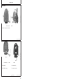
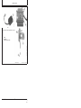
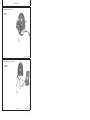
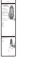
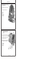
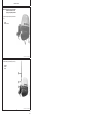
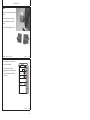
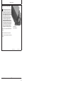
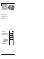
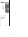
STARFIRE Real Time Kinematic (RTK) INSTALLATION INSTRUCTIONS STARFIRE Real Time Kinematic (RTK) PC20235 18DEC03 (ENGLISH) John Deere Ag Management Solutions PC20235 (18DEC03) COPYRIGHT 2003 DEERE & COMPANY Moline, Illinois All rights reserved A John Deere ILLUSTRUCTION Manual PC20235-19-18DEC03 Installation Instructions Introduction IMPORTANT: Read through this instruction thoroughly and familiarize yourself with process before performing procedure. This instruction covers installation of Real Time Kinematic (RTK) on your STARFIRE system. OUO6084,0001B83 –19–08SEP03–1/1 Installation Time Installation time of Real Time Kinematic (RTK) varies considerably depending on what receiver is being mounted to. Installation time will typically take between 1—3 hours with an average installation time of 1.5 hours. OUO6043,00016F9 –19–30MAY03–1/1 PC20235 (18DEC03) 1 Installation Instructions 121803 PN=3 Installation Instructions Parts List PF90258 Vehicle Bundle • • • • • • PF11579 PF80608 PF80611 PF80623 PF80631 PF80677 PF90260 Base Station with Universal Mounting Bracket and STARFIRE Screws, Phillips #8-32, 7/16 in. (2 Used) Radio Harness, STARFIRE RTK Rover Bracket STARFIRE Antenna, Low Gain Cable, Antenna Extension • • • • • • • PF90259 Base Station with Tripod and STARFIRE • • • • • • • • • • PF80610 Harness, STARFIRE RTK Base Station PF80625 Bracket, Tripod PF80629 RTK Radio Kit PF80632 Tripod PF80633 Harness, No TCM Plug PF80647 Harness, STARFIRE RTK Base Receiver PF80654 Assembly, Receiver and Radio PF80655 Case PF80656 Case Insert PF80657 Receiver, STARFIRE Gen. II – 21M7267 Screw, M6X20 (6 Used) – PC20234 Instruction, Licensing STARFIRE – PF10134 Cover, Upper GPS Receiver – PF10135 Cover, Lower GPS Receiver – PF80385 Position Receiver – PF80611 Harness, STARFIRE RTK Rover – PF80623 Bracket STARFIRE • PF80660 Harness, Power Adaptor PF80610 PF80623 PF80625 PF80629 PF80632 PF80633 PF80647 PF80655 PF80656 PF80660 Bracket, RTK Base Station Mount Bracket, RTK Base Station Quick Tach Harness, STARFIRE RTK Base Station Harness, STARFIRE RTK Base Receiver Bracket, RTK Base Station Assembly, Receiver and Radio Harness, Power Adaptor PF90264 Base Station with Universal Mounting Bracket, Less STARFIRE • • • • • • • PF80610 PF80623 PF80629 PF80633 PF80647 PF80653 PF80660 Harness, STARFIRE RTK Base Station Bracket STARFIRE RTK Radio Kit Harness, No TCM Plug Harness, STARFIRE RTK Base Receiver Bracket, RTK Base Station Harness, Power Adaptor Attachments • • • • • PF90263 Base Station with Tripod, Less STARFIRE • • • • • • • • • • PF11621 PF11622 PF80610 PF80647 PF80653 PF80654 PF80660 Harness, STARFIRE RTK Base Station Bracket STARFIRE Bracket, Tripod RTK Radio Kit Tripod Harness, No TCM Plug Harness, STARFIRE RTK Base Receiver Case Case Insert Harness, Power Adaptor PF80632 Tripod PF80646 Harness, RTK Receiver Extension Harness PF80652 Harness, RTK Radio Extension Harness PF80653 Bracket, RTK Base Station PF90261 Repeater – Bolt, #8-1/2 in. Phillips (2 Used) – 19H1866 Bolt (2 Used) – N10217 Nut (2 Used) – PF11542 Bracket, Repeater – PF11614 Magnet (2 Used) – PF11625 Weld Nut – PF80608 RTK Radio – PF80609 Harness, STARFIRE RTK Repeater – PF80630 Assembly Repeater Bracket – PF80631 Antenna, Low Gain – PF80660 Harness, Power Adaptor – PF80666 Assembly, Repeater Magnetic Mount OUO6043,00016FB –19–30MAY03–1/1 PC20235 (18DEC03) 2 Installation Instructions 121803 PN=4 Installation Instructions –UN–12DEC03 N64436 N64437 –UN–12DEC03 Radio Installation Without TCM With TCM A—Screws (Four Used) B—Shroud 1. Remove four screws (A) and lower shroud (B). N64438 –UN–12DEC03 –UN–12DEC03 OUO6050,0000501 –19–16DEC03–1/11 N64439 Without TCM With TCM A—Screws (Two Used) B—TCM C—Harness 2. Remove screws (A). 4. Disconnect harness (C). 3. Remove TCM (B)—if equipped. 5. Discard harness and bracket. Continued on next page PC20235 (18DEC03) 3 OUO6050,0000501 –19–16DEC03–2/11 Installation Instructions 121803 PN=5 –UN–16DEC03 N64447 N64441 –UN–18DEC03 Installation Instructions Radio 6. Attach radio (A) to new bracket (B) with 7/16 in. screws (C). N64449 –UN–16DEC03 A—Radio B—New Bracket C—Screw, Phillips, 7/16 in. (2 Used) Continued on next page PC20235 (18DEC03) 4 OUO6050,0000501 –19–16DEC03–3/11 Installation Instructions 121803 PN=6 Installation Instructions 7. Connect RTK harness (A) to receiver (B). N64448 –UN–16DEC03 A—RTK Harness B—Receiver OUO6050,0000501 –19–16DEC03–4/11 8. Connect RTK harness (A) to radio harness (B). N64450 –UN–16DEC03 A—RTK Harness B—Radio Harness Continued on next page PC20235 (18DEC03) 5 OUO6050,0000501 –19–16DEC03–5/11 Installation Instructions 121803 PN=7 Installation Instructions IMPORTANT: If base station does not have a TCM, a cap is required on TCM connector on harness or STARFIRE will not function. NOTE: RTK Vehicles REQUIRE a TCM. Base stations DO NOT REQUIRE a TCM. 9. Receivers without TCM: Connect RTK harness to TCM cap (A) and position section of harness in upper receiver shroud as shown. –UN–18DEC03 10. Position radio harness (B) in upper receiver shroud as shown. 11. Position harness (C) as shown. N64462 12. Attach receiver (D) and bracket (E) with screws (F). A—TCM Cap B—Radio Harness C—Harness D—Receiver E—Bracket F—Screws (2 Used) OUO6050,0000501 –19–16DEC03–6/11 13. Receivers with TCM:Connect RTK harness (A) to TCM (B). N64451 –UN–16DEC03 A—RTK Harness B—TCM Continued on next page PC20235 (18DEC03) 6 OUO6050,0000501 –19–16DEC03–7/11 Installation Instructions 121803 PN=8 Installation Instructions 14. Receivers with TCM:Attach receiver (A), bracket (B), and TCM (C) with screws (D). 15. Route radio harness (E) in upper receiver shroud as shown. 16. Route harness (F) over bracket as shown. N64453 –UN–16DEC03 A—Receiver B—Bracket C—TCM D—Screw (2 Used) E—Radio Harness F—Harness OUO6050,0000501 –19–16DEC03–8/11 IMPORTANT: System failure can occur if harness is pinched. Ensure harness is routed properly. 17. Position lower shroud (A) and upper shroud (B) together using care not to pinch any of the harnesses. 18. Harness connected to radio should have a drip loop (C) before going into receiver shroud. 19. Connector (D) is routed out of receiver on opposite side of bracket from harness connected to radio. N64454 –UN–16DEC03 A—Lower Shroud B—Upper Shroud C—Drip Loop D—Connector Continued on next page PC20235 (18DEC03) 7 OUO6050,0000501 –19–16DEC03–9/11 Installation Instructions 121803 PN=9 Installation Instructions IMPORTANT: System failure can occur if harness is pinched. Ensure harness is routed properly prior to tightening hardware. 20. Attach shroud (A) with previously removed screws (B). N64464 –UN–18DEC03 A—Shroud B—Screws (Four Used) OUO6050,0000501 –19–16DEC03–10/11 21. Attach extension (A) and antenna (B) to radio (C). N64461 –UN–18DEC03 A—Extension B—Antenna C—Radio With TCM OUO6050,0000501 –19–16DEC03–11/11 PC20235 (18DEC03) 8 Installation Instructions 121803 PN=10 Installation Instructions Vehicle 1. Attach radio to receiver. (See RADIO INSTALLATION section.) –UN–26SEP03 2. Attach bracket on receiver to bracket on vehicle. PC7866 3. Connect STARFIRE harness to GREENSTAR harness. N64444 –UN–12DEC03 4. Calibrate TCM. See AutoTrac Operator’s manual. GREENSTAR is a trademark of Deere & Company OUO6050,00004F6 –19–03DEC03–1/2 5. Enter RTK activation. See RTK Operator’s manual. 6. Go to SETUP/STARFIRE/PAGE3. SETUP • Set RTK Operating Mode to VEHICLE. • Set RTK Network ID to match Base Station Network ID. • Set RTK Radio Channel to match Base Station Radio Channel. JOHN DEERE GPS PAGE 3 RTK Operating Mode VEHICLE A RTK Radio Channel (1-14) 1 B RTK Network ID (1-4000) 1 C D E F PC7983 G –19–04NOV03 Configure Repeater Radio OUO6050,00004F6 –19–03DEC03–2/2 PC20235 (18DEC03) 9 Installation Instructions 121803 PN=11 Installation Instructions N64457 CAUTION: Mounting location should be fixed firmly so movement of receiver is not possible. If base station receiver is allowed to move it will result in warnings and could result in vehicle movement. Mounting receiver on tall towers or grain legs, which can shift in wind, is not recommended. Radio and antenna assembly can be mounted in a higher location with optional harness (PF80652) to improve radio line of sight but receiver should be positioned so that it will not move. Mount a receiver close to a metal building can cause GPS interference. If GPS can not be acquired after installation change location or increase height of receiver. –UN–16DEC03 Absolute (24 Hour Survey) Base Station A—Universal Bracket B—Receiver Quick Coupler 1. Attach radio to receiver. (See RADIO INSTALLATION section.) 2. Attach universal bracket (A) to mounting location. 3. Attach receiver quick coupler (B) to universal mounting bracket. Continued on next page PC20235 (18DEC03) 10 OUO6050,00004FA –19–10DEC03–1/3 Installation Instructions 121803 PN=12 Installation Instructions N64444 –UN–12DEC03 CAUTION: Always attach harness to power source before connecting STARFIRE receiver harness. Make sure power inverter has a minimum capacity of 3 amps. A smaller inverter could overheat or cause operational problems. If a battery is used, it is recommended to permanently attach eyelet terminals to 12V battery. Use of alligator type clips is not recommended as they can expose operators to sparks. 4. Connect receiver harness to power harness. 5. Connect power harness to power inverter or battery. 6. Use enclosed VELCRO straps to secure harness. 7. Attach GREENSTAR display to harness. 8. Power system. VELCRO is a trademark of Velcro Industries B.V. OUO6050,00004FA –19–10DEC03–2/3 9. Enter RTK activation. See RTK Operator’s manual. JOHN DEERE • Set RTK Operating Mode to ABSOLUTE BASE. • Set RTK Network ID to match Vehicle Network ID. • Set RTK Radio Channel to match Vehicle Radio Channel. IMPORTANT: Base station coordinates are stored in receiver. If receiver is changed these values can be entered into display for new receiver if operator does not want to perform another 24 hour survey. 11. Record base station location ID and coordinates. GPS PAGE 3 RTK Operating Mode ABSOLUTE BASE A RTK Radio Channel (1-14) 1 B RTK Network ID (1-4000) 1 C Configure Repeater Radio D Edit Stored RTK Base Locations (1-20) E F G –19–13NOV03 10. Go to SETUP/STARFIRE/PAGE3. PC8022 SETUP OUO6050,00004FA –19–10DEC03–3/3 PC20235 (18DEC03) 11 Installation Instructions 121803 PN=13 Installation Instructions N64460 N64459 –UN–16DEC03 –UN–16DEC03 Quick Survey Base Station A—Tripod B—Latch 2. Position tripod (A) ensuring lever (B) is pushed down to fully lock each leg. CAUTION: If tripod latches are loose, tighten hardware to ensure positive locking of tripod legs. Movement of tripod can cause unexpected vehicle motion. 1. Attach radio to receiver. (See RADIO INSTALLATION section.) Continued on next page PC20235 (18DEC03) 12 OUO6050,00004FB –19–10DEC03–1/4 Installation Instructions 121803 PN=14 Installation Instructions 3. Attach bracket (A) to tripod (B). N64458 –UN–16DEC03 A—Bracket B—Tripod Continued on next page PC20235 (18DEC03) 13 OUO6050,00004FB –19–10DEC03–2/4 Installation Instructions 121803 PN=15 Installation Instructions 4. Attach receiver to bracket. 5. Connect STARFIRE harness to power harness. CAUTION: Always attach harness to power source before connecting STARFIRE receiver harness. It is recommended to permanently attach eyelet terminals to 12V battery. Use of alligator type clips is not recommended as they can expose operators to sparks. –UN–18DEC03 6. Install battery harness to battery. 7. Attach GREENSTAR Display to harness. N64466 8. Connect power harness to battery harness. N64444 –UN–12DEC03 9. Use enclosed VELCRO straps to secure harness. OUO6050,00004FB –19–10DEC03–3/4 10. Go to SETUP/STARFIRE/PAGE3. • Set RTK Operating Mode to QUICK SURVEY BASE. • Set RTK Network ID to match Vehicle Network ID. N64463 –19–18DEC03 NOTE: In QUICK SURVEY mode, base station STARFIRE will automatically perform quick survey and send differential corrections to RTK vehicle. OUO6050,00004FB –19–10DEC03–4/4 PC20235 (18DEC03) 14 Installation Instructions 121803 PN=16 Installation Instructions Repeater 1. Go to either RTK vehicle or base station. 2. Program Network ID and Radio channel as shown above. 3. Disconnect radio on vehicle (or base station). 4. Connect repeater radio. –UN–18DEC03 5. Go to SETUP/STARFIRE/PAGE 3. 6. Press button next to “Configure Repeater Radio”. N64465 7. Wait for radio to configure. 8. Disconnect repeater radio. 9. Reconnect radio on vehicle (or base station). 10. Attach repeater to mounting location. SETUP JOHN DEERE GPS PAGE 3 11. Connect repeater harness to repeater radio. RTK Operating Mode VEHICLE 12. Connect to battery. RTK Radio Channel (1-14) 1 B 13. Use enclosed VELCRO straps to secure harness. RTK Network ID (1-4000) 1 C A D E F PC7983 G –19–04NOV03 Configure Repeater Radio OUO6050,00004FC –19–10DEC03–1/1 PC20235 (18DEC03) 15 Installation Instructions 121803 PN=17 Installation Instructions PC20235 (18DEC03) 16 Installation Instructions 121803 PN=18


![[児童相談所]総括表(PDF形式:24KB)](http://vs1.manualzilla.com/store/data/006592233_2-91d8af743501e566144ab3491b0e5593-150x150.png)