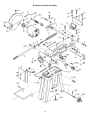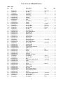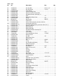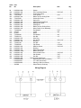
1
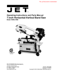
OWNER'S MANUAL
HVBS-56M Horizontal/Vertical Bandsaw
JET EQUIPMENT & TOOLS, INC.
A WMH Company
www.jettools.com
P.O. BOX 1349
Auburn, WA 98071-1349
e-mail [email protected]
Phone:253-351-6000
Fax: 1-800-274-6840
M-414458 12/2000
Important Information
1-YEAR
JET offers a one-year limited
warranty on this product
LIMITED WARRANTY
REPLACEMENT PARTS
Replacement parts for this tool are available directly from JET Equipment & Tools.
To place an order, call 1-800-274-6848. Please have the following information ready:
1. Visa, MasterCard, or Discover Card number
2. Expiration date
3. Part number listed within this manual
4. Shipping address other than a Post Office box.
REPLACEMENT PART WARRANTY
JET Equipment & Tools makes every effort to assure that parts meet high quality and durability standards
and warrants to the original retail consumer/purchaser of our parts that each such part(s) to be free from
defects in materials and workmanship for a period of thirty (30) days from the date of purchase.
PROOF OF PURCHASE
Please retain your dated sales receipt as proof of purchase to validate the warranty period.
LIMITED TOOL AND EQUIPMENT WARRANTY
JET makes every effort to assure that its products meet high quality and durability standards and warrants to the
original retail consumer/purchaser of our products that each product be free from defects in materials and
workmanship as follows: 1 YEAR LIMITED WARRANTY ON THIS JET PRODUCT. Warranty does not apply to
defects due directly or indirectly to misuse, abuse, negligence or accidents, repairs or alterations outside our facilities
or to a lack of maintenance. JET LIMITS ALL IMPLIED WARRANTIES TO THE PERIOD SPECIFIED ABOVE FROM
THE DATE THE PRODUCT WAS PURCHASED AT RETAIL. EXCEPT AS STATED HEREIN, ANY IMPLIED
WARRANTIES OR MECHANTABILITY AND FITNESS ARE EXCLUDED. SOME STATES DO NOT ALLOW
LIMITATIONS ON HOW LONG THE IMPLIED WARRANTY LASTS, SO THE ABOVE LIMITATION MAY NOT
APPLY TO YOU. JET SHALL IN NO EVENT BE LIABLE FOR DEATH, INJURIES TO PERSONS OR PROPERTY
OR FOR INCIDENTAL, CONTINGENT, SPECIAL OR CONSEQUENTIAL DAMAGES ARISING FROM THE USE OF
OUR PRODUCTS. SOME STATES DO NOT ALLOW THE EXCLUSION OR LIMITATION OF INCIDENTAL OR
CONSEQUENTIAL DAMAGES, SO THE ABOVE LIMITATION OR EXCLUSION MAY NOT APPLY TO YOU. To
take advantage of this warranty, the product or part must be returned for examination, postage prepaid, to an
authorized service station designated by our Auburn office. Proof of purchase date and an explanation of the
complaint must accompany the merchandise. If our inspection discloses a defect, JET will either repair or replace the
product or refund the purchase price, if we cannot readily and quickly provide a repair or replacement, if you are
willing to accept such refund. JET will return repaired product or replacement at JET’s expense, but if it is determined
there is no defect, or that the defect resulted from causes not within the scope of JET’s warranty, then the user must
bear the cost of storing and returning the product. This warranty gives you specific legal rights, and you have other
rights, which vary, from state to state.
JET Equipment & Tools • P.O. Box 1349, Auburn, WA 98071-1349 • (253) 351-6000
2
WARNING
Read and understand the entire instruction manual before operating machine.
This machine is designed and intended for use by properly trained and experienced personnel
only. If you are not familiar with the proper safe use of bandsaws, do not use this machine until
proper training and knowledge has been obtained.
•
•
•
•
•
•
•
•
•
•
•
•
•
•
•
•
•
•
•
•
•
•
•
•
•
•
•
Always wear approved safety glasses/face shields while using this machine.
Make certain the machine is properly grounded.
Before operating the machine, remove tie, rings, watches, other jewelry, and roll up sleeves above
the elbows. Remove all loose clothing and confine long hair. Do not wear gloves.
Keep the floor around the machine clean and free of scrap material, oil and grease.
Keep machine guards in place at all times when the machine is in use. If removed for maintenance
purposes, use extreme caution and replace the guards immediately.
Do not over reach. Maintain a balanced stance at all times so that you do not fall or lean against
blades or other moving parts.
Make all machine adjustments or maintenance with the machine unplugged from the power source.
Use only sharp tools. Dull tools are dangerous
Replace warning labels if they become obscured or removed.
Make certain the switch is in the OFF position before connecting the machine to the power supply.
Give your work undivided attention. Looking around, carrying on a conversation, and "horse-play"
are careless acts that can result in serious injury.
Keep visitors a safe distance from the work area.
Use recommended accessories; improper accessories may be hazardous.
Make a habit of checking to see that keys and adjusting wrenches are removed before turning on
the machine.
Never attempt any operation or adjustment if the procedure is not understood.
Keep fingers away from the blade when the machine is running.
Never hand hold material with the saw in the horizontal position. Always use the vise and clamp it
securely.
Keep belt guard and wheel covers in place and in working order.
Never force the cutting action.
Do not attempt to adjust or remove tools during operation.
Always provide adequate support for long and heavy material.
Always use identical replacement parts when servicing.
Read and understand all warnings posted on the machine.
This manual is intended to familiarize you with the technical aspects of this bandsaw. It is not, nor
was it intended to be, a training manual.
Failure to comply with all of these warnings may cause serious injury.
Some dust created by power sanding, sawing, grinding, drilling and other construction activities
contains chemicals known to cause cancer, birth defects or other reproductive harm. Some
examples of these chemicals are:
• Lead from lead based paint
• crystalline silica from bricks and cement and other masonry products, and
• arsenic and chromium from chemically-treated lumber.
Your risk from those exposures varies, depending on how often you do this type of work. To reduce
your exposure to these chemicals: work in a well ventilated area, and work with approved safety
equipment, such as those dust masks that are specifically designed to filter out microscopic particles
3
Specifications:
HVBS-56M
Stock Number................................................................................................................................ 414458
Horizontal Capacity:
Round @ 90°....................................................................................................................................5”
Round @ 45°....................................................................................................................................3”
Rectangle @ 90° ....................................................................................................................... 5” x 6”
Rectangle @ 45° ....................................................................................................................... 5” x 3”
Throat Depth...........................................................................................................................................6”
Vertical Work Table Size...................................................................................................... 9-5/8” x 9-1/2”
Vise Swivels .........................................................................................................................................45°
Blade Size ...............................................................................................................1/2” x 0.025” x 64-1/2”
Blade Wheel Diameter ......................................................................................................................7-3/8”
Speeds ........................................................................................................................80, 120, 200 SFPM
Bed Height......................................................................................................................................25-1/2”
Floor Space Required ...................................................................................................... 16-1/4” x 42-1/2”
Motor (UL listed) ........................................................................... 1/2 HP, 1 Ph, 115/230V, prewired 115V
Net Weight (approx.)......................................................................................................................115 lbs.
Table of Contents
Page
Warranty.................................................................................................................................................. 2
Warnings ................................................................................................................................................. 3
Specifications & Table of Contents........................................................................................................... 4
Unpacking & Clean-Up ............................................................................................................................ 5
Tools Supplied for Assembly.................................................................................................................... 5
Tools Required for Assembly ................................................................................................................... 5
Assembly..............................................................................................................................................5-7
Vertical Cutting Plate Assembly ............................................................................................................7-8
Electrical Connections ............................................................................................................................. 8
Changing Blade Speed ............................................................................................................................ 9
Adjusting Blade Guides............................................................................................................................ 9
Adjusting Blade Tension .......................................................................................................................... 9
Changing Blades ................................................................................................................................... 10
Adjusting Blade Guide Bearings............................................................................................................. 10
Adjusting Blade Tracking ....................................................................................................................... 11
Adjusting Feed Pressure........................................................................................................................ 11
Adjusting Automatic Shut-Off ................................................................................................................. 12
Adjusting the Vise .................................................................................................................................. 12
Breakdown for Bow Assembly................................................................................................................ 13
Breakdown for Base Assembly............................................................................................................... 14
Parts List .......................................................................................................................................... 15-17
Wiring Diagram...................................................................................................................................... 17
The specifications in this manual are given as general information and are not binding. JET Equipment &
Tools reserves the right to effect, at any time and without prior notice, changes or alterations to parts,
fittings, and accessory equipment deemed necessary for any reason whatsoever.
4
Unpacking and Clean-Up
Note: Read and understand the entire manual
before attempting setup or operation.
1. Remove all contents form the shipping
carton.
2. Inspect contents for shipping damage and
report any damage to your distributor.
3. Wipe bed and vise assembly with clean
cloth to remove excess oil used to prevent
rust.
4. Do not discard any packing material until
saw has been assembled and is running
properly.
Tools Supplied for Assembly
1. Wrench 12/14mm
Tools Required for Assembly
•
•
•
•
•
#2 Cross Point Screwdriver
6-8" Adjustable Wrench or Wrench Set
Pliers - Regular or Needle Nose
4mm Angle Hex Wrench
Ratchet and Sockets will Speed Assembly
Assembly
1. With the help of another person turn the saw
over so that it rests on the motor and saw
bow, Figure 1. Place it on a piece of
cardboard, or a surface that will not damage
the saw.
2. Attach a cross brace (A, Fig. 1) to the motor
side of the bed using three 5/16”x1” hex cap
bolts, six 5/16” flat washers, and secure with
three 5/16” hex nuts. Hint: Tighten the nut
(B, Fig. 1) on the end of the bed first
followed by the nuts on the sides.
3. Attach a leg to the cross brace using four
5/16”x3/4” carriage bolts, four 5/16” flat
washers and four 5/16” hex nuts. Use a
12mm wrench to tighten. Repeat for other
leg.
4. Remove the brace (C, Fig. 1) on the
opposite end of the bed and bow using a
10mm wrench.
5
5. Attach a cross brace to the opposite end of
the bed using three 5/16”x1” hex cap bolts,
six 5/16” flat washers, and secure with three
5/16” hex nuts. Tighten the nut on the end
of the bed first followed by the nuts on the
sides.
6. Attach a leg to the cross brace using four
5/16”x3/4” carriage bolts, four 5/16” flat
washers and four 5/16” hex nuts. Use a
12mm wrench to tighten. Repeat for other
leg.
7. Attach the adjustable feet (A, Fig. 2) to the
legs opposite of the motor, using the
provided hardware.
8. Slide the axle (A, Fig. 3) through the legs.
Place a large flat washer (B, Fig. 3) on both
sides of the wheels and place on the axle.
Secure wheels with two split pins (C, Fig. 3).
9. Carefully turn the saw onto its stand and
adjust the feet so the bed is level.
10. Put the handle (A, Fig. 4) through holes in
the stand legs opposite of the wheel
assembly and secure with split pins.
6
11. Slide pulley cover (A, Fig. 5) around motor
shaft and worm gear shaft. Secure with two
hex cap screws and washers (B, Fig. 5).
12. Lift motor with one hand while the other
hand places V-belt (C, Fig.5) on both pulleys.
13. Attach the tension bracket (D, Fig. 5) to the
saw bow with one 5/16”x3/4” hex head bolt
and flat washer (E, Fig. 5).
14. Connect the two tension brackets with one
5/16”x3/4” carriage bolt, one 5/16” flat
washers and one 5/16” hex nut (F, Fig. 5).
Hint: Insert the carriage bolt from the inside
so the hex nut is easy to access with a
wrench.
15. Tension belt by pressing down on the motor
while tightening hex nut (F, Fig. 5) until
finger pressure on the belt between the two
pulleys causes approximately 1/2" deflection.
Close pulley cover. Don’t over tighten the
belt.
16. Insert stop rod (A, Fig. 6) into bed and
tighten set screw (B, Fig. 6). Slide stock
stop (C, Fig. 6) onto rod and tighten set
screw (D, Fig. 6) to hold in place.
17. Slide handwheel (E, Fig. 6) onto shaft and
secure by tightening set screw (F, Fig. 6).
Make sure set screw seats on flat portion of
shaft.
Vertical Cutting Plate Assembly
Note: These steps are only necessary when
using the bandsaw in the vertical mode.
WARNING
Disconnect the bandsaw from the power
source before making any repairs or
adjustments!
Failure to comply may cause serious injury!
1. Disconnect the bandsaw from the power
source.
2. Raise the arm to the vertical position and
lock in place with lever (A, Fig. 7).
3. Loosen bolt (B, Fig. 7) and insert bracket (C,
Fig. 7). Tighten bolt just enough to hold the
bracket in place.
7
4. Remove two screws (D, Fig. 7) and plate (E,
Fig. 7).
5. Guide blade through slot in table (A, Fig. 8)
and fasten table with two screws (B, Fig. 8).
6. Fasten support bracket to underside of table
using screw (C, Fig. 8) and hex nut.
7. Tighten bolt (B, Fig 7).
Electrical Connections
WARNING
All electrical connections must be completed
by a qualified electrician.
Failure to comply may cause serious injury!
The HVBS-463 bandsaw is rated at 115/230V
and comes from the factory prewired 115V.
To switch to 230V operation, follow the wiring
diagram found on the inside of the motor
junction box. The plug on the end will have to
be replaced with a plug that is rated at 230V.
This bandsaw is designed for use on a circuit
with an outlet that looks like (A, Fig. 9). The
bandsaw has a grounding prong as illustrated in
(B, Fig. 9). A temporary adapter (C, Fig. 9) may
be used to connect the plug to a two pole
receptacle (D, Fig. 9) if a properly grounded
outlet is not available. The temporary adapter
should only be used until a properly grounded
outlet can be installed by a qualified electrician.
The green colored lug must be securely
fastened to the cover plate screw.
Before hooking up to the power source, be sure
the switch is in the off position.
8
the blade guide assemblies as far apart as
possible. Lock in place.
Changing Blade Speed
1. Disconnect the machine from the power
source.
4. Depress blade. Finger pressure should
cause approximately .004" deflection. Turn
blade tension knob (B, Fig. 12) until the
proper tension is achieved. Re-position
guides for cutting material.
2. Place saw arm in the horizontal position.
3. Loosen tensioning plate hex nut (A, Fig.10).
4. Open pulley cover (B, Fig. 10). Lift motor
with one hand while placing the belt (C, Fig.
10) on the desired pulley combination.
5. Tension belt by pressing down on the motor
while tightening hex nut (A, Fig. 10) until
finger pressure on the belt between the two
pulleys causes approximately 1/2" deflection.
Close pulley cover. Don’t over tighten the
belt.
6. Close pulley cover and connect to power
source.
The general rule for band saw blade speed is
the harder the material being cut, the slower the
blade speed. Reference Figure 11 for a guide to
blade speed for a type of material being cut.
Adjusting Blade Guides
1. Disconnect machine from the power
source.
2. Loosen knob (A, Fig. 12) and slide blade
guide assembly (B, Fig. 12), as close as,
possible without interference to the material
being cut. Tighten knob.
3. Loosen bolt (C, Fig.12) and slide blade
guide assembly (D, Fig. 12), as close as,
possible without interference to the material
being cut. Tighten bolt
Adjusting Blade Tension
1. Disconnect machine from the power
source.
2. Open blade cover and observe the position
of the blade on the wheel. If the blade is not
next to the wheel flange, adjust blade
tracking following the steps under "Adjusting
Blade Tracking".
3. If the blade is next to the wheel flange,
loosen the blade guide assembly lock knob
and hex head bolt (A & C, Fig. 12) and slide
9
Changing Blades
1. Disconnect machine from the power
source.
3. Loosen nut (B, Fig. 14) and turn nut (C, Fig.
14) to adjust eccentric bearing to a
clearance of .001". Tighten nut (B, Fig. 14)
to lock.
2. Raise the saw arm to the vertical position
and lock in place with lock lever.
4. Connect machine to power source.
3. Open blade cover by removing the small
knob found on the topside of the bow.
4. Remove red blade guards by removing two
screws.
WARNING
It is essential these two guards be installed
after the new blade has been fitted. Failure
to comply may cause serious injury!
5. Release tension on the blade by turning
tensioning knob (B, Fig. 12), and remove the
blade.
6. Place new blade between the blade guide
assemblies and around each wheel. Make
sure blade teeth are pointing in the proper
direction, Figure 13. Tension enough to
hold in place.
7. Install red blade guards with two screws.
8. Tension blade fully, see “Adjusting Blade
Tension”.
9. Place two to three drops of lightweight oil on
the blade.
10. Connect machine to the power source.
11. Run saw and make sure blade is tracking
properly, see "Adjusting Blade Tracking".
As a general rule, the thinner the material to be
cut, the more teeth per inch on the blade. A
minimum of three teeth should be in contact with
the material at all times during the cut. If the
teeth straddle the material, severe damage can
result to the material and the blade.
Adjusting Blade Guide Bearings
1. Disconnect machine from the power
source.
2. Loosen bolt (A, Fig. 14) and adjust assembly
so that back roller bearing is
approximately .002" - .003" from the back of
the blade. Tighten bolt.
10
feed pressure. If they are still burned and heavy,
reduce the blade speed. Optimum feed
pressure has been set when the chips are curled,
silvery, and warm.
Adjusting Blade Tracking
WARNING
Blade tracking adjustment requires running
the saw with the back cover open! This
adjustment must be completed by qualified
persons only!
Failure to comply may cause serious injury!
Blade tracking has been set at the factory and
should not need adjustment. If blade tracking
needs to be adjusted:
1. Confirm that blade tension is set properly.
To adjust, see section titled " Adjusting
Blade Tension".
2. Make sure the saw is in its slowest speed,
see “Changing Blade Speeds”.
3. Move saw arm to the vertical position and
lock in place with the lock lever.
4. Confirm that blade tension is set properly.
To adjust, see section titled " Adjusting
Blade Tension".
5. Open blade cover by removing the knob
found on the top side of the bow.
6. Run saw and observe blade. Blade should
run next to but not tightly against wheel
flange.
7. Loosen bolts (A, Fig. 15).
8. Turn set screw (B, Fig. 15) while observing
blade tracking on wheel. Turn set screw
clockwise to track closer to wheel flange.
Turn set screw counter-clockwise to track
away from the wheel flange. Hint: start
with ¼ turns on the set screw. The tracking
is sensitive.
9. Once tracking is set, tighten bolts (A, Fig.
15).
Adjusting Feed Pressure
1. Turn handle (A, Fig. 16) clockwise to
decrease cutting pressure and counterclockwise to increase cutting pressure.
A good indication of proper feed pressure is the
color and shape of the cutting chips. If the chips
are thin or powdered, increase the feed pressure.
If the chips are burned and heavy, decrease the
11
2. Place saw arm in the horizontal position.
Adjusting Automatic Shut-Off
3. Remove screws (A, Fig. 18) from the gear
box and remove cover plate and gasket.
The saw should stop after the cut has been
completed:
•
If the saw completes the cut and continues
to run, adjust the stop tip (A, Fig. 17) down.
•
If the saw shuts off before the cut is
complete, adjust the stop tip (A, Fig. 17) up.
•
If the saw stops cutting but continues to run,
adjust the stop bolt (B, fig. 17) down.
4. Hold a container under the lower right corner
of the gear box with one hand while slowly
raising the saw arm with the other. Drain
completely.
5. Place arm in the horizontal position. Wipe
out remaining oil with a rag.
6. Fill gear box with approximately 1/2 pint of
MOBIL SHC 634.
7. Replace gasket and cover. Fasten cover
with bolts.
The saw is properly adjusted when the saw
shuts off just after the blade has finished the cut.
Adjusting the Vise
1. To open and close the vise use the
handwheel (C, Fig. 17).
2. The vise can be adjusted for square and
miter cuts. Loosen the hex cap bolts and
adjust the vise for the cut.
3. Adjust the blade guides so they are as close
as possible to the material without interfering.
4. There is a scale on the back side of the bed
to aid in setting up the vise for 90° cuts or a
particular miter. Hint: Always check the
vise setup with a combination square,
against the blade and vise, so that you can
verify the vise setting is correct.
Lubrication
Ball bearings on the blade guide assemblies and
the blade wheels are permanently sealed and
require no lubrication.
Lubricate the vise lead screw as needed with #2
tube grease.
Gear box oil will have to be changed after 90
days of operation. There after, change every six
months.
To change the gear box oil:
1. Disconnect machine from the power
source.
12
Breakdown for Bow Assembly
13
Breakdown for Base Assembly
14
Parts List for the HVBS-56M Bandsaw
Index Part
No.
No.
Description
Size
Qty.
1..........TS-0051031 ..............................Hex Cap Bolt......................................... 5/16”x3/4” ................... 4
2..........TS-0561011 ..............................Hex Nut................................................. 1/4”............................. 1
3..........TS-0680021 ..............................Flat Washer........................................... 1/4”............................. 5
4..........HVBS56M-04 ............................Stand Leg ............................................. ................................... 4
4-1.......HVBS56M-04-1 .........................Cross Brace .......................................... ................................... 2
5..........HVBS56M-05 ............................Washer ................................................. ................................... 6
6..........HVBS462-006 ...........................Cotter Pin.............................................. 1/8”x1”........................ 4
7..........HVBS56M-07 ............................Axle....................................................... ................................... 1
8..........TS-0680031 ..............................Flat Washer........................................... 5/16”......................... 36
9..........HVBS56M-09 ............................Wheel ................................................... ................................... 2
10 ........HVBS56M-010 ..........................Washer ................................................. 1/4”x5/8” ..................... 1
11 ........TS-0051051 ..............................Hex Cap Bolt......................................... 5/16”x1” ...................... 4
11-1.....HVBS56M-11-1 .........................Carriage Bolt ......................................... 5/16”x3/4” ................. 16
11-2.....TS-0051051 ..............................Hex Cap Bolt......................................... 5/16”x1” ...................... 6
12 ........TS-0561021 ..............................Hex Nut................................................. 5/16”......................... 22
13 ........HVBS56M-013 ..........................Adjustable Foot ..................................... ................................... 2
14 ........HVBS462-014 ...........................Floor Stand Handle ............................... ................................... 1
15 ........HVBS462-015 ...........................Adjusting Rod........................................ ................................... 1
16 ........HVBS462-016 ...........................Electric Cord ......................................... ................................... 1
17 ........HVBS462-017 ...........................Pivoting Rod.......................................... ................................... 1
18 ........HVBS462-018 ...........................Support Plate ........................................ ................................... 1
19 ........HVBS462-019 ...........................Stock Stop............................................. ................................... 1
20 ........TS-0270021 ..............................Socket Set Screw.................................. 5/16”x5/16” ................. 4
21 ........HVBS462-021 ...........................Stock Stop Rod ..................................... ................................... 1
22 ........HVBS462-022 ...........................Wire Relief Retainer .............................. ................................... 2
25 ........TS-0051031 ..............................Hex Cap Bolt......................................... 5/16”x3/4” ................... 1
27 ........HVBS462-027 ...........................Wheel Handle ....................................... ................................... 1
28 ........HVBS462-028 ...........................Hand Wheel .......................................... ................................... 1
29 ........HVBS56M-029 ..........................Toggle Switch Assembly ....................... ................................... 1
29-1.....HVBS56M-029-1 .......................Plastic Cover......................................... ................................... 1
30 ........HVBS462-030 ...........................E-Ring................................................... E10............................. 1
31 ........HVBS462-031 ...........................Screw.................................................... 5/16”x1” ...................... 3
32 ........HVBS462-032 ...........................Lead Screw ........................................... ................................... 1
33 ........HVBS462-033 ...........................Vise Nut ................................................ ................................... 1
34 ........HVBS462-034 ...........................Moveable Vise Plate.............................. ................................... 1
35 ........TS-0680041 ..............................Flat Washer........................................... 3/8”x1”........................ 6
36 ........TS-0090061 ..............................Hex Cap Bolt......................................... 3/8”x1-1/4” .................. 1
37 ........HVBS462-037 ...........................Bed ....................................................... ................................... 1
38 ........HVBS462-038 ...........................Cross Round Head Screw ..................... 3/16”x3/8” ................... 2
39 ........HVBS462-039 ...........................Scale..................................................... ................................... 1
40 ........HVBS462-040 ...........................Electric Cord Clip .................................. ................................... 1
42 ........HVBS56M-042 ..........................Screw.................................................... M4x16 ........................ 2
43 ........HVBS462-043 ...........................Rubber Ring.......................................... ................................... 1
44 ........HVBS462-044 ...........................Electric Cable........................................ ................................... 1
45 ........HVBS462-045 ...........................Nut Plate ............................................... ................................... 1
45-1.....HVBS56M-045-1 .......................Spring Handle Bracket........................... ................................... 1
46 ........HVBS462-046 ...........................Spring Adjusting Screw ......................... ................................... 1
47 ........HVBS462-047 ...........................Spring ................................................... ................................... 1
48 ........HVBS462-048 ...........................Cross Round Head Screw ..................... 3/16”x3/8” ................... 4
49 ........HVBS462-049 ...........................Mitering Vise Plate ................................ ................................... 1
50 ........TS-0081031 ..............................Hex Cap Bolt......................................... 5/16”x3/4” ................... 6
51 ........TS-0680031 ..............................Flat Washer........................................... 5/16”........................... 3
15
Index Part
No.
No.
Description
Size
Qty.
52 ........TS-0081071 ..............................Hex Cap Bolt......................................... 5/16”x1-1/2” ................ 1
53 ........TS-0091071 ..............................Hex Cap Screw ..................................... 7/16”x2” ...................... 1
54 ........HVBS56M-054 ..........................Pivot Bracket......................................... ................................... 1
55 ........HVBS462-055 ...........................Vertical Cutting Plate............................. ................................... 1
56 ........HVBS462-056 ...........................Stand for Vertical Cutting Plate.............. ................................... 1
57 ........HVBS56M-057 ..........................Adjustable Bracket Assembly LH........... ................................... 1
58 ........HVBS462-058 ...........................Knob ..................................................... 1/4”............................. 1
59 ........HVBS56M-059 ..........................Blade Back Safety Cover....................... ................................... 1
60 ........HVBS462-060 ...........................C-Clip.................................................... S10............................. 4
61 ........BB-6000ZZ................................Ball Bearing........................................... 6000ZZ....................... 6
62 ........HVBS462-062 ...........................Guide Pivot ........................................... ................................... 2
............HVBS462-062A.........................Center Shaft Assembly (Includes: #60-62)................................. 1
62-1.....HVBS462-062-1 ........................Centrifugal Guide Pivot.......................... ................................... 2
............HVBS462-062-1A......................Eccentric Shaft Assembly (Includes: #60,61,62-1) ..................... 1
63 ........HVBS462-063 ...........................Bearing Shaft Pin .................................. ................................... 2
64-1.....HVBS462-064-1 ........................Blade Seat Left...................................... ................................... 1
64-2.....HVBS462-064-2 ........................Blade Seat Right ................................... ................................... 1
65 ........HVBS56M-065 ..........................Adjustable Bracket-Assembly RH .......... ................................... 1
66 ........HVBS462-066 ...........................Lock Knob............................................. ................................... 1
67 ........TS-0720081 ..............................Lock Washer ......................................... 5/16”........................... 3
68 ........TS-0813051 ..............................Flat Head Machine Screw...................... 1/4”X3/4”..................... 3
69 ........HVBS462-069 ...........................Bearing Guard....................................... ................................... 1
70 ........TS-0561031 ..............................Hex Nut................................................. 3/8”............................. 8
71 ........HVBS462-071 ...........................Blade Wheel Drive................................. ................................... 1
72 ........HVBS462-072 ...........................Bearing Cover ....................................... ................................... 2
73 ........HVBS462-073 ...........................Key ....................................................... 5x5x25........................ 2
74 ........HVBS56M-060 ..........................C-Clip.................................................... S15............................. 1
75 ........HVBS462-075 ...........................Hex Cap Bolt (w/Washer) ...................... 1/4”x1/2” ..................... 8
76 ........HVBS462-076 ...........................Switch Cut Off Trip ................................ ................................... 1
77 ........HVBS462-077 ...........................Idle Blade Wheel ................................... ................................... 1
78 ........TS-0680031 ..............................Flat Washer........................................... 5/16”........................... 2
79 ........HVBS462-079 ...........................Blade Tension Knob .............................. 3/8”............................. 1
80 ........HVBS462-080 ...........................Spring ................................................... ................................... 1
81 ........HVBS56M-081 ..........................Saw Bow............................................... ................................... 1
82 ........HVBS56M-082 ..........................Washer ................................................. ................................... 1
83 ........TS-0070031 ..............................Cap Screw ............................................ 1/2”x1-1/2” .................. 2
84 ........HVBS56M-084 ..........................Motor Mount Plate................................. ................................... 1
84-1.....HVBS56M-084-1 .......................Tension Bracket .................................... ................................... 1
85 ........HVBS463-085 ...........................Motor .................................................... 1/2 HP, 1Ph ................ 1
............HVBS463-085-01 ......................Capacitor Cover (not shown) ................. ................................... 1
............HVBS462-085-02 ......................Capacitor (not shown) ........................... ................................... 1
86 ........HVBS462-086 ...........................Motor Pulley .......................................... ................................... 1
87 ........BB-6202ZZ................................Ball Bearing........................................... 6202ZZ....................... 6
88 ........HVBS462-088 ...........................Bearing Bushing.................................... ................................... 1
89 ........OS-15375 .................................Oil Seal ................................................. ................................... 2
90 ........HVBS462-090 ...........................Transmission Wheel Shaft..................... ................................... 1
91 ........HVBS462-091 ...........................Worm Gear ........................................... ................................... 1
92 ........HVBS462-092 ...........................Gear Box Gasket................................... ................................... 1
93 ........HVBS462-093 ...........................Gear Box Cover .................................... ................................... 1
94 ........HVBS462-094 ...........................Worm Gear (w/Shaft) ............................ ................................... 1
95 ........HVBS462-095 ...........................Spring Pin ............................................. ................................... 1
96 ........HVBS462-096 ...........................Bearing Bushing.................................... ................................... 1
97 ........TS-0050011 ..............................Hex Cap Bolt......................................... 1/4”x1/2” ..................... 3
98 ........HVBS56M-098 ..........................Clamp ................................................... ................................... 2
16
Index Part
No.
No.
Description
Size
Qty.
99 ........HVBS462-099 ...........................Spacer .................................................. ................................... 1
100 ......HVBS462-100 ...........................Flat Cross Head Screw.......................... 5/32”x3/8” ................... 8
101 ......HVBS462-101 ...........................Worm Gear Pulley................................. ................................... 1
102 ......TS-0720081 ..............................Lock Washer ......................................... 5/16”........................... 2
103 ......HVBS462-103 ...........................Blade Tension Sliding Plate................... ................................... 1
104 ......TS-0270051 ..............................Socket Set Screw.................................. 5/16”x1/2” ................... 3
105 ......HVBS462-105 ...........................Spring Pin ............................................. ................................... 1
106 ......HVBS462-106 ...........................Sliding Plate Draw Block ....................... ................................... 1
107 ......HVBS462-107 ...........................Blade Wheel Shaft................................. ................................... 1
108 ......HVBS462-108 ...........................Shaft Block............................................ ................................... 1
109 ......HVBS462-109 ...........................Blade Tension Sliding Guide ................. ................................... 2
110 ......HVBS462-110 ...........................Motor Pulley Cover Assembly................ ................................... 1
111 ......TS-0680031 ..............................Flat Washer........................................... 5/16”........................... 1
112 ......VB-A22 .....................................V-Belt.................................................... A22............................. 1
113 ......414301......................................Blade .................................................... ................................... 1
114 ......TS-0680041 ..............................Flat Washer........................................... 3/8”............................. 4
115 ......TS-0561011 ..............................Hex Nut................................................. 1/4”............................. 1
116 ......HVBS463-170 ...........................Wire Plug .............................................. ................................... 3
117 ......HVBS463-171 ...........................Hex Screw............................................. 3/8”x1-1/4” .................. 1
120 ......HVBS462-120 ...........................Bushing................................................. ................................... 1
122 ......TS-0561041 ..............................Hex Nut................................................. 7/16”........................... 1
123 ......TS-0050031 ..............................Cap Screw ............................................ 1/4”x3/4” ..................... 1
124 ......HVBS463-124 ...........................Machine Screw...................................... 3/16”x3/4” ................... 2
126 ......HVBS462-126 ...........................Bushing................................................. ................................... 1
132 ......HVBS462-132 ...........................Blade Guard-Right................................. ................................... 1
132-1 ...HVBS462-132A.........................Blade Guard-Left................................... ................................... 1
156 ......HVBS462-156 ...........................Round Head Screw ............................... 3/16”x3/4” ................... 1
157 ......HVBS462-157 ...........................Star Washer .......................................... 3/16”........................... 3
158 ......HVBS463-158 ...........................Hex Nut................................................. 3/16”........................... 3
159 ......HVBS462-159 .................. Round Cross Head Screw ............................. 3/16”.........................1
............HVBS56M-BS ...........................Blade Speed Label (not shown) ............. ................................... 1
............HVBS56M-ID ............................I.D. Label (not shown) ........................... ................................... 1
............HVBS56M-WL...........................Warning Label (not shown).................... ................................... 1
............JM-56M.....................................Stripe Decal (not shown) ....................... ................................... 1
Wiring Diagram
17