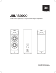
1
Version 9/14/95
M
9
5
0
7/27/98 2:58 PM
0
M
O
N
I
Page 1
T
O
R
O
L
W
M9500
O
N
U
E
D
R
S
S
P
M
E
A
A
K
N
E
U
R
A
S
L
Version 9/14/95
7/27/98 2:58 PM
Page 2
GENERAL SYSTEM DESCRIPTION
The JBL M9500 monitor loudspeaker system represents a
refinement of the principles that have guided JBL’s high-level
monitor system design over the last thirty years.
In keeping with contemporary monitoring practice, the system
is essentially of two-way design. A horn-compression driver
section covers the frequency range from 650Hz to20kHz.
Located above and below the high-frequency section are
mirror-imaged low-frequency transducers in ported enclosures.
The stereo pair of loudspeakers exhibits both vertical and
horizontal symmetry for effective “point source” radiation and
for accurate stereophonic imaging. All transducers make use of
shielded neodymium magnets, and the systems can be used in
proximity to video monitors with no interference.
The M9500 system uses stand-alone dividing networks that
facilitate various electronic options, including bi-wiring, triwiring, and biamplification. The networks are designed around
the finest components available and make use of dc bias on
the capacitors for greater linearity.
A single M9500 system is capable of producing sine wave output levels of 110 dB Lp at one meter with extremely low
distortion. In terms of wide band program, this translates into
levels of 120 dB Lp for the stereo pair at normal listening
distances of 2 and 3 meters.
The enclosures are made of thick sections of mediumdensity fiberboard, liberally braced, and have an attractive,
scuff-resistant finish.
Unpacking and Inspection
The complete M9500 system is shipped in eight containers, as
detailed below:
2 — Lower low-frequency enclosures
2 — High-frequency/horn enclosures
2 — Upper low-frequency enclosures
1 — Dividing networks (2 networks in one package,
including 6 hook-up cables and 4 9-volt batteries)
1 — Low-frequency grilles
(4 in one package)
Make sure that you have all containers. Unpack them carefully
and inform your JBL dealer of any sign of damage. It is
recommended that you save the packaging for future use.
Version 9/14/95
7/27/98 2:58 PM
Page 3
System Setup
The M9500 systems are modular, each consisting of a stack of
three separate enclosures. The larger of the bass enclosures
are placed at the bottom, and the high-frequency/horn modules
stack on top and are aligned by the screws that protrude on
the bass section. The smaller bass modules are placed on top
of the high-frequency modules and are similarly aligned.
We recommend that you do not assemble the M9500 systems
until you have determined their best location in your listening
room or control room. In general, the listening angle for best
stereo imaging should be in the range from 45 to 60 degrees
and the loudspeakers should be placed no closer than about 25
or 30 cm (10" or 12") from the wall behind them. Sidewalls
should be somewhat farther away, and the loudspeakers
should be toed inward toward the primary listening position.
The room itself should be quiet, well-damped, and free of
obvious flutter echoes or standing waves.
Connect the loudspeakers to the networks using the cables
provided. Note that there are different cables for highfrequency and low-frequency hookup; they cannot be
intermixed. For positive contact, insert the Speakon ®
connectors and turn them one-eighth turn clockwise.
Figure 1. Electronic hookup
options; views of the rear
panel of the dividing
network. A, single full-range
amplification; B, bi-wiring
with two amplifiers; C, triwiring with three amplifiers;
and D, biamplification with
external electronic dividing
network and separate highand low-frequency
amplifiers.
A
Biamp
Electronic Options
Norm
Your next concern is the amplifier/ loudspeaker operating mode.
The various hookup options are shown in Figure 1. We will
describe each of these options:
HF +
0
–
R
HF
R
LF1
B
Option B, bi-wiring. In this mode, identical power amplifier
sections are fed full-range program; one amplifier is connected
to the high-frequency portion of the system, and the other is
fed to the low frequency sections in parallel. Many users will
use a large stereo amplifier to drive the low- frequency
sections and a smaller one for the high-frequency sections.
Make sure that the stereo amplifier used for the paralleled
low-frequency sections can deliver the necessary power into
4 ohms.
Input
R
LF2
I
B
B
Biamp
Norm
HF +
0
–
R
HF
B
R
LF1
B
To M9500
Option A, single full-range amplifier. This mode of operation
requires a relatively large, high-quality amplifier capable of
delivering up to 800 watts per channel into 4-ohms. Note that
all sections of the network are connected in parallel with the
straps provided.
To M9500
B
R
LF2
Input
B
C
Biamp
Norm
HF +
0
–
R
HF
B
R
LF1
B
R
LF2
Input
B
To M9500
Option C, tri-wiring. This mode of operation is similar to B,
but with each low-frequency section driven by its own
amplifier. In this case, each low-frequency amplifier section will
look into 8 ohms.
Page 4
R
Option D, biamplification. This mode of operation requires
aLF1
B
dedicated electronic dividing network crossing over atR 650 Hz.
LF2
We recommend the JBL DX-1 with internal
compensation
B
Input
made for the M9500 system. If this mode is used, make sure
that the screwdriver adjustment on the back of each network
is set in the “biamp” position.
HF out
Electronic dividing
network
(650 Hz crossover) LF out
High-frequency trim switches on the Input
back of the networks provide three settings (zero, plus, and minus) so that the systems can be
trimmed for the acoustical characteristics of the listening
space.
D
Biamp
HF +
Norm
–
0
R
HF
B
R
LF1
B
R
LF2
B
Regardless of the operating mode you choose, we recommend
that only the finest hookup wire be used between the amplifiers and dividing networks. We recommend that the wire size
be no smaller than 3.3 square millimeter cross-section (#12
AWG). The inputs to the networks can accommodate spade
lugs, pins, bare wire, or individual banana connectors.
The internal 9-volt battery that is used to bias the capacitors
will normally last at least 5 years. You may test it by pressing
the gold logo on the front of the network. If the LED on the
front of the network illuminates, the battery is functional and
need not be replaced.
,
,
,
,
,,,,,,,
,
,
,
,,,
,
,
,
,
,
,
,,,, , ,
,,,
,,
,,,,,,,
,
,
,,
,,,,,,
,,,
,
,
,
,
,
,
,
,
,,,
,,,,
,,
,,,,
,,,
,,,
,,
,
,
,
,,
,,,, , ,
,,,,,,,
Diecast aluminum housing
,,,,
Front cover
Silver plated pole piece
,,,,,
,
,
The
Transducers
Serpentine phone plug
Aquaplas-dusted
titanium diaphragm
,
,,,,,
,
,
,
,
,
,,,,,
,
,
,,
,,,
,
,,,
,,
,,,,
,
,,
,,,
,
,
,
,
,
,
,,,,
,
,,,
,,,,
,
,
,
,
,,
,
,
,,,
,,
,,,,
,,,,
,,,,
,,,
,,,
,,,,
,,
,,,
,,,,
,,,,
Top plate
Return circuit
Aluminum shorted turn
,,,,,,,,
,,,,,,
,,,,
,,,,,,,,,,,,
,,,,,,
Foam acoustic pad
Neodymium magnet
Threaded mounting holes
,,
,,
Figure 2. Cutaway view of
JBL 475Nd high-frequency
compression driver. Note
the curved (equalized) paths
from the diaphragm to the
driver's output.
Copper shorted turn
Cooling vent (1 of 3)
Neodymium magnet
Return circuit
Edgewood aluminum
ribbon voice coil
Centering spider
Diecast frame/
magnet chassis
Fiberglas/Aquaplas
composite cone
Foam compliance
Throat
Screen
Figure 3. Cutaway view of
JBL 1400Nd low-frequency
transducer. Note both
aluminum and copper
shorting rings.
To M9500
7/27/98 2:58 PM
To M950
Version 9/14/95
Version 9/14/95
7/27/98 2:58 PM
Page 5
The JBL model 475Nd compression driver used in the M9500
has a smooth titanium dome 101 millimeters in diameter that
has been lightly coated with Aquaplas™ damping compound.
Its aluminum ribbon voice coil operates in a magnetic flux field
of 1.65 tesla (16,500 gauss). Mid-band efficiency is 20%, while
at the peak value of driver impedance it is in excess of 50%.
The driver uses JBL’s Coherent Wave™ phasing plug, which
provides equalized path lengths from all sections of the
diaphragm to the driver's output. The driver is mounted on the
H9500 horn, a design used only in this system that provides
smooth loading down to 500 Hz and exhibits consistent
horizontal dispersion over its operating range.
There are two JBL model 1400Nd low-frequency transducers
in each loudspeaker system. A single 1400Nd is capable
of handling instantaneous input signals of 600 watts,
corresponding to a midband peak output of 118 dB Lp at a
distance of one meter. The transducer’s second and third
harmonic distortion have been reduced through the use of
JBL’s traditional aluminum shorting ring at the base of the pole
piece, as well as through the use of a copper shorting ring on
the top plate adjacent to the voice coil. The transducers make
use of JBL’s Vented Gap Cooling™ in which forced air,
generated by cone motion, removes heat produced by the
voice coil. Each driver is mounted in its own ported enclosure,
and the two enclosures are “stagger tuned” to provide
smoother and more extended low-frequency response.
Cutaway views of the high-frequency and low-frequency
transducers are shown in Figures 2 and 3.
Typical System Performance Measurements
The high-frequency response of the M9500 system was carefully established by making a series of measurements over
frontal angles of 60° in both vertical and horizontal planes. This
allows for optimal listening over a wide area. The frequency
response averaged over the 60° horizontal and vertical angles,
measured from 200 Hz to 20 kHz, is shown in Figure 4. Here,
the network High Frequency trim is set in its zero position.
The slight downward trend was incorporated, based on
extensive listening tests to contemporary pop/rock and
classical recordings.
+10
Figure 4. Averaged frontal
angle response (60°,
horizontal and vertical) of
M9500 from 200 Hz to 20
kHz.
dB
Relative level (dB)
0
–10
–20
–30
2
3
4
5 6 7 8 9 10
100
1.5
2
3
4
5 6 7 8 9 10
1000
1.5
2
3
4
5 6 7 8 9 10
1.5
10000
2
Version 9/14/95
7/27/98 2:58 PM
Page 6
Directivity Factor, Q
Directivity Index, DI (dB)
The directivity index (DI) of the H9500 horn is shown in Figure
5. The smoothly rising DI is a consequence of the gradual
narrowing of the vertical dispersion angle above 2 kHz and
contributes to the overall flatness of the high-frequency
response of the system.
20
100
10
10
0
20
50
100
200
500
1000
Frequency (Hz)
2000
5000
10000
1
20000
Figure 5. Plot directivity
index (DI) and directivity
factor (Q) of the H9500.
Overall system on-axis pressure response and impedance are
shown in Figure 6. The contributions of the paralleled lowfrequency sections and the high-frequency section are shown
individually along with their acoustical summation. The overall
slopes in the crossover region are a combination of electrical
(network) and acoustical response.
M9500
4.3V @ 1.5 m
HF @ "0"
100dB
Anecmoil
Ground
Plane
10 Ω
2
3
4
5 6 7 8 910
100
1.5
2
3
4
5 6 7 8 9 10
1.5
1000
2
3
4
5 6 7 8 9 10
1.5
10000
2
Figure 6. On-axis response
of M9500. Individual
contributions of paralleled
low-frequency transducers
and high-frequency section
are shown, along with their
summation. The impedance
curve is also given, showing
a minimum value of 3 ohms
in the 100 Hz range.
The second and third harmonic distortion of the system is
shown in Figure 7. Here, the system is driven with sine wave
input to produce an output of 96 dB Lp at a distance of 1
meter. An output of 96 dB with a sine wave input corresponds
to extremely high system output with wide band program
material. Distortion curves have been raised 20 dB, and the values seen here lie well below 1% for the lowest frequencies up
to 4.5 khz, reaching a value of only 1.6% at 10 kHz. Not many
loudspeakers can demonstrate such low levels of distortion as
shown here.
96dB
Distortion Raised 20dB
Solid = Second Harm.
Dash = Third Harm.
M9500
Distortion
3.0V @ 1 m
2
3
4
5 6 7 8 910
100
1.5
Figure 7. Second and third
harmonic distortion for
fundamental of 96 dB Lp at
a distance of 1 meter.
(Distortion raised 20 dB)
2
3
4
5 6 7 8 9 10
1.5
1000
2
3
4
5 6 7 8 9 10
1.5
10000
2
Version 9/14/95
7/27/98 2:58 PM
Page 7
Care and Maintenance of the System
Your M9500 monitors should give years of trouble-free service.
Normally, the only routine maintenance will be cleaning. The
grilles may be cleaned of dust gently with a vacuum cleaner
using a brush attachment. If there should be stains on the
grille, a soft bristle brush moistened with a dilute mixture of
water and dishwashing detergent may be used. The same
mixture may be used for cleaning the enclosure finish itself
if it has become smudged.
As mentioned before, the 9-volt batteries in the dividing networks will last perhaps as long as their normal shelf life. You
may expect them to last at least 5 years. If the LED no longer
lights, remove the acrylic door on the front of the network and
replace them.
System Specifications
Acoustic and Electrical Specifications:
Sensitivity:
95 dB for 2.83 V @ 1 meter
Rated Impedance (LF parallel): 4 Ohms
Minimum Impedance:
3.0 Ohms @ 100 Hz
Frequency Response:
35 Hz to 20 kHz (half space)
Crossover Frequency:
650 Hz
System Polarity:
EIA (positive voltage to red terminal
produced outward cone motion)
System Components and Physical Specifications:
Low-Frequency Transducer:
1400 Nd
High-Frequency Transducer: 475 Nd
Horn Assembly:
H9500
Dividing Network:
N9500
Enclosure Volumes:
78 liters (2.8 cu ft) 35 Hz tuning (upper LF)
115 liters (4.1 cu ft) 28 Hz tuning (lower LF)
System Dimensions:
140 mm H x 330 mm W x 403 mm D
(55"H x 15.13"W x 15.88"D)
Total depth including horn 521 mm (20.5")
Weight:
38.2 kg (84 lbs) upper LF
54.5 kg (120 lbs) lower LF
37.3 kg (82 lbs) horn assembly
Version 9/14/95
7/27/98 2:58 PM
Page 8
JBL continually strives to improve its products. New materials, production methods and design refinements are introduced into existing
models without notice as a routine expression of our design philosophy.
For this reason, JBL M9500 Series Loudspeakers may differ in some
respect from their published specifications and descriptions, but will
always equal or exceed the original specifications unless otherwise
stated.
JBL Consumer Products, Inc.
80 Crossways Park West
Woodbury, NY 11797
8500 Balboa Blvd.
Northridge, CA 91329
800 645 7484
Printed in USA on recycled paper 9/95
Part No. JBLM9500M