1
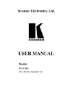
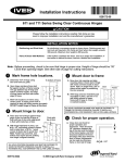
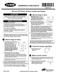
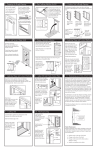
Installation Instructions 829168-00 112HD & 224HD Series Concealed Continuous Hinges ! CAUTION Please follow the installation instructions carefully. Not doing so may result in improper installation and void the manufacturers guarantee. These hinges have a permanent, factory applied lubricant. Removal or alteration of this lubricant, anodizing or painting of the product in the field will void the guarantee. INSTALLATION NOTES Reinforcing and Rivet nuts: No reinforcing is necessary except on extremely high frequency, extremely heavy or extra-wide doors. Rivet nuts are required in the frame and door when door weight exceeds 450 pounds (up to 600 pounds). Pairs of Doors with Mullions: If the mullion is between the doors, treat as a single door installation. If the mullion is behind the doors, treat as a double door installation. HINGE CUTTING (IF NECESSARY) Note: All standard length hinges are supplied slightly shorter than nominal door height to avoid threshold or carpeting clearance problems. All uncut hinges are templated and non-handed. Use the same model for both right and left hand openings. If hinge is longer than door and needs cut, follow instructions below. Once the hinge is cut it becomes handed because the cut end must go on bottom. 1 Determine hinge height. If hinge is taller than door, hinge must be cut to match door height. Hinge must not be taller than door height. Mark hinge with line where cut is needed. 2 Cut hinge. A. Fold hinge so that channel is up. B. Starting on channel, cut through entire hinge along line. C. Debur all cut edges with file. 3 Special note, when cutting off more than 13.50. Set screw A. If more than 13.5 is cut from bottom of hinge, a set screw bearings will be cut off. This set screw bearing is required for proper operation. bearing B. In this case remove the set screw bearing from the cut off section by loosening set screw and sliding back channel. C. Loosen set screw(s) on hinge, slide back channel, and replace a non set screw bearing with a set screw bearing. D. Slide channel back into place and tighten all set screws. ! CAUTION 83, 85, and 95 hinges require 2 set screw bearings. 120 hinges require 3 set screw bearings. 829168-00(1) © 2006 Ingersoll-Rand Company Limited Channel INSTALLATION 1 Mark frame hole locations. A. Open hinge and place frame leaf flat against surface of frame leaving 1/8” gap between top of hinge and frame header. Hinge lip should be held tight against the frame face from top to bottom. 1/8” B. Mark all hole locations on frame using center punch provided. C. Drill all holes using #13 (.185”) or 3/16” (.188”) drill for metal frame. For wood frame use 5/32” (.156”) drill. Optional wood screw pack required. D. DO NOT install hinge to frame at this time. 2 Mount hinge to door. Flush Doo r Mount door to frame A. With door held securely, position door 90 degrees to opening and align mounting holes in frame leaf of hinge with marks on frame made in step 1. Note: An angle block, jack or shims will be helpful in positioning the door properly. Frame Door B. With hinge and door held securely and accurately in place, install #12-24 flat head screw through top hole in frame leaf of hinge and into frame. Align other holes and install all other remaining screws. 4 Check for proper operation and clearances. A. Close door and check for proper operation. 1/8” B. Check push side of door for proper clearances. Clearance for single door is shown to the right and double door is shown below. 5/16” 1/8” Do or A. Place door leaf of hinge against hinge edge of door so that top of hinge is flush with top of door. Hinge aligment lip must lay flat against full length of door. 3 C. Check with NFPA 80 manual for clearance requirements on FIRE-RATED openings. Top view B. With hinge held firmly in place, mark all hole locations on frame using center punch. C. Drill all holes as in step 1. D. Attach hinge leaf to door using fasteners provided and #3 phillips drive. See screw chart below. Note: Fasten top screw first, and bottom most screw second, making sure hinge is aligned correctly. 1/8” 5/16” 1/8” 5/16” Screw Chart Door & Frame Material 3/16” Screw Type Metal frame & metal door #12-24 flat head screws Metal frame & wood door* #12-24 flat head screws (frame) #12 x 1-1/2” flat head wood screws (door) Wood frame* & wood door* #12 x 1-1/2” flat head wood screws *Optional wood screw pack required. Page 2 of 2 829168-00(1)