1
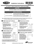
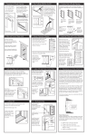
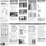
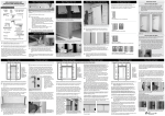
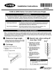
Installation Instructions 829171-00 602 and 702 Series Surface Continuous Hinges ! CAUTION Please follow the installation instructions carefully. Not doing so may result in improper installation and void the manufacturers guarantee. INSTALLATION NOTES Reinforcing and Rivet Nuts: No reinforcing is necessary except on heavy doors. Reinforcement and rivet nuts are required in the frame and door when door weight exceeds 300 pounds. Maximum door weight is 600 pounds. 2 IMPORTANT NOTE: FOR ALL UL FIRE LABEL DOORS, 1/4-20 X 1-3/4 STEEL THROUGH BOLTS MUST BE USED FOR FASTENING THE HINGE TO THE DOOR. 1 Frame B. With hinge held firmly and accurately to frame, place 1/4-20 x 3/4 self drilling screws through cover clips and screw into frame through mounting holes in hinge leaf. Cover clips should be located at the top and bottom mounting holes, and equally spaced along the length of the frame leaf. C. Install remaining 1/4-20 x 3/4 self drilling screws through mounting holes in frame leaf. ALL HOLE LOCATIONS ON HINGE LEAF MUST BE FASTENED TO FRAME FOR PROPER OPERATION. FAILURE TO INSTALL ALL FASTENERS WILL VOID WARRANTY AND UL FIRE LABEL LISTINGS. 1/16 NOTE: There should be 1/8 clearance between the top of the door and the bottom of the frame header and 1/8 clearance between the edge of the door and frame. An angle block, jack or shims will be helpful in positioning the door properly. Check to be sure hinge leaf is square to door with 1/16 gap from edge of frame to centerline of hinge barrel the full length of the hinge. B. With hinge and door held firmly and accurately in place, use 1/4-20 x 3/4 self drilling screws through cover clips and screw into door through mounting holes in door leaf. Cover clips should be located at top and bottom mounting holes, and equally spaced along the length of the door leaf. ALL HOLE LOCATIONS ON HINGE LEAF MUST BE FASTENED TO DOOR FOR PROPER OPERATION. FAILURE TO INSTALL ALL FASTENERS WILL VOID WARRANTY AND UL FIRE LABEL LISTINGS. 3 Check for proper operation. A. Close door and check for proper operation and clearances. 1/8 1/8 4 Mount screw covers. A. After door has been checked for proper operation and all mounting screws have been tightened, engage short leg of cover to barrel side of clip. B. Tap cover onto outside clip with rubber mallet so that long leg of cover sets against frame of door surface. DO NOT DAMAGE COVER. NOTE: FOR THIN METAL FRAMES (18 GAUGE OR THINNER) THE USE OF RIVET NUT STYLE FASTENERS IS RECOMMENDED. 829171-00(0) Edge of door Install remaining 1/4-20 x 3/4 self drilling screws through mounting holes in door leaf. Mount hinge to frame. A. Place frame leaf of hinge on face of frame so that there is 1/8 gap 1/8 between top of hinge and underside of frame header, and 1/16 gap between edge of the frame and the center line of the hinge barrel. Check to be sure hinge leaf is square to frame with 1/16 gap from edge of frame to centerline of hinge barrel the full length of the hinge. 1/16 1/8 Frame A. Move door into opening and place door leaf of hinge on face of door so that top of door is flush with top of hinge and center line of hinge barrel is 1/16 from edge of door. Pairs of Doors with Mullions: If the mullion is between the doors, treat as a single door installation. If the mullion is behind the doors, treat as a double door installation. Note: Before proceeding, check to be sure that hinge is proper size. Height of hinge should be 7/8 LESS than opening height. See other side of page for cutting instructions. Mount hinge to door. © 2006 Ingersoll-Rand Company Limited Instructions for Cutting Hinge 1 Determine hinge height. 4 A. Measure height of opening from finished floor to underside of door frame header. Shorten hinge pin 3/4. A. Using center punch or heavy nail, tap on cut surface of hinge pin to remove top hinge tip (save tip for step 5). B. Expose 1 of hinge pin. Measure and mark 3/4 from end of pin. B. Hinge height is height of opening MINUS 7/8. DOUBLE CHECK MEASUREMENT BEFORE CUTTING. Height of opening MINUS 7/8 2 C. Cut pin at mark. Mark hinge for cutting. Top A. Determine which end of hinge will be the TOP using door and frame as a guide. B. Open hinge to expose back of hinge (holes are NOT countersunk). C. Measure hinge height calculated in step 1 from top of hinge. 3/4 Opening height minus 7/8 D. Using square, mark a line on back of both hinge leaves and the barrel. 5 Insert top and bottom tip. A. Tap hinge pin back into barrel. Cutting line Bottom B. Tap hinge pin tips (retained from step 3 and 4) firmly into top and bottom of barrel until shoulder sets squarely on barrel. NOTE: Both tips MUST BE INSTALLED to hold hinge pin in position. DOUBLE CHECK MEASUREMENT BEFORE CUTTING! NOTE: Cut end of hinge must be used as BOTTOM OF HINGE ONLY! 3 Save tip Cut hinge. A. Fold hinge so that cut line is visible. B. Starting on barrel, cut through entire hinge along line. C. Debur all cut edges with file. D. Use center punch or heavy gauge nail on pin in short cut off portion of hinge to remove hinge tip. SAVE HINGE TIP for use in step 5. 6 Save tip Page 2 of 2 Important Note: If more than 6 is cut from bottom of hinge, additional mounting holes will be required on bottom of hinge. Use cut off piece of hinge to mark and prepare hole locations on bottom of hinge. 829171-00(0)