1
IRIS
DC1100/DC1100E
Business Class Cable Modem Termination System
Installation and Operational Guide
Coaxial Networks, Inc.
P/N DC1100-UG
Revision: 4.13
This page intentionally left blank
Coaxial Networks, Inc.
Page 2 of 60
Table of contents
Software License.......................................................................................... 7
Limited Warranty ........................................................................................ 8
Introduction................................................................................................... 11
Key Benefits .............................................................................................. 11
Installation Requirements.......................................................................... 12
Package Contents ...................................................................................... 12
IRIS Rear Panel Connections .................................................................... 13
IRIS Front Panel ........................................................................................ 14
Mounting the IRIS Unit............................................................................. 14
Setup ............................................................................................................. 17
Connecting Your IRIS DC1100 ................................................................ 17
Checking Conditions Prior to System Startup .......................................... 17
Starting the System.................................................................................... 17
Configuring Your IRISDC1100 ................................................................ 17
Coaxial Cable Specifications..................................................................... 18
Connections................................................................................................... 19
Cable Network Diagram............................................................................ 19
Configuration ................................................................................................ 21
Configuring IRIS ....................................................................................... 21
Logging into IRIS...................................................................................... 21
Creating Class of Service Profiles............................................................. 30
Controlling Cable Modem Access ............................................................ 32
Application Notes ......................................................................................... 43
Network traffic between cable clients....................................................... 43
Allowing PPPoE traffic across IRIS ......................................................... 43
Static IP Mapping ...................................................................................... 43
Channel Frequency Chart ............................................................................. 45
NTSC Channel Frequency Chart in MHz (DOCSIS) ............................... 45
PAL Frequency Allocation (EuroDOCSIS).............................................. 49
Regulatory Compliance ................................................................................ 53
Agency Standards...................................................................................... 53
VI (Visual) Editor.......................................................................................... 55
Entering the vi............................................................................................ 55
Insert/Overtype Mode................................................................................ 55
Command Mode ........................................................................................ 55
Entering Insert Mode ............................................................................. 55
Coaxial Networks, Inc.
Page 3 of 60
vi Syntax................................................................................................. 55
Miscellaneous 1 ...................................................................................... 57
ex Commands......................................................................................... 58
ex syntax................................................................................................. 58
The vi environment variables................................................................. 59
File Saving and Loading ........................................................................ 59
Coaxial Networks, Inc.
Page 4 of 60
Table of Figures
Figure 1 IRIS Rear Panel .................................................................................................. 13
Figure 2 IRIS Front Panel ................................................................................................. 14
Figure 3 Attaching mounting braces for flat wall mount.................................................. 15
Figure 4 Flat Wall Mount ................................................................................................. 15
Figure 5 Connections with Integrated Upconverter.......................................................... 19
Figure 6 Connections with an external Upconverter ........................................................ 20
Figure 7 IRIS Uplink Connection ..................................................................................... 20
Figure 8 Web Login .......................................................................................................... 22
Figure 9 Setup home page................................................................................................. 22
Figure 10 IRIS Configuration Page .................................................................................. 23
Figure 11 Save and reboot ................................................................................................ 24
Figure 12 Network Setup .................................................................................................. 25
Figure 13 Bridge mode setup............................................................................................ 26
Figure 14 Bridge Mode Configuration ............................................................................. 27
Figure 15 Downstream RF Settings.................................................................................. 28
Figure 16 Upstream RF Settings....................................................................................... 29
Figure 17 Class of Service Creation ................................................................................. 30
Figure 18 Cable Modem Subscription .............................................................................. 33
Figure 19 Telnet login prompt .......................................................................................... 35
Figure 20 IRIS CLI prompt............................................................................................... 36
Figure 21 List of CLI commands...................................................................................... 37
Figure 22 List of registered cable modems....................................................................... 37
Figure 23 List of SID and their MAC addresses............................................................... 38
Figure 24 List of CPEs connected to the CMs.................................................................. 38
Coaxial Networks, Inc.
Page 5 of 60
This page intentionally left blank
Coaxial Networks, Inc.
Page 6 of 60
Copyright © 2001-2005, Coaxial Networks, Inc.
All rights reserved. Printed in USA
Product names mentioned herein may be trademarks and/or registered trademarks of their respective
companies. Coaxial Networks, Inc. shall not be liable for technical or editorial errors or omissions in this
document; nor for incidental or consequential damages resulting from the furnishing, performance, or use
of this material.
No part of this publication may be reproduced in any form or by any means without written permission
from Coaxial Networks, Inc. Coaxial Networks provides this publication “as is”, without warranty of any
kind, either express or implied, including, but not limited to, the implied warranties of merchantability or
fitness for a particular purpose. Changes are periodically made to the information in this publication. These
will be incorporated in subsequent editions. Coaxial Networks may make improvements and/or changes to
the product(s) described in this publication at any time.
Coaxial Networks, Inc. - End User Software License and Limited Warranty
INSTALLATION OF THE HARDWARE AND SOFTWARE PROVIDED BY COAXIAL
NETWORKS, INC. (“CNI”) CONSTITUTES ACCEPTANCE BY YOU OF THE TERMS
OF THE FOLLOWING SOFTWARE LICENSE AND LIMITED WARRANTY. IF YOU
DO NOT ACCEPT THESE TERMS, PLEASE RETURN THE HARDWARE AND
SOFTWARE IN ITS ORIGINAL PACKAGING TO COAXIAL NETWORKS FOR A
FULL REFUND OF THE PURCHASE PRICE EXCLUDING SHIPPING COST.
The following describes your license to use the software (the "Software") that has been provided
with your CNI IRIS Cable Modem Termination System equipment ("Hardware") and the limited
warranty that CNI provides on its Software and Hardware.
Software License
The Software is protected by copyright laws and international copyright treaties. The Software is licensed
and not sold to you. Accordingly, while you own the media (CD ROM or floppy disk) on which the
Software is recorded, CNI retains ownership of the Software itself.
1. Grant of License. You may install and use one (and only one) copy of the Software on the system on
which the Hardware is being installed.
2.
Restrictions. The license granted is a limited license. You may NOT:
• Sublicense, assign, or distribute copies of the Software to others;
• Decompile, reverse engineer, disassemble or otherwise reduce the Software or any part thereof to a
human perceivable form;
• Modify, adapt, translate or create derivative works based upon the Software or any part thereof; or
• Rent, lease, loan or otherwise operate for profit the Software.
3. Transfer. You may transfer the Software only where you are also transferring the Hardware. In such
cases, you must remove all copies of the Software from any devices onto which you have installed it, and
must ensure that the party to whom you transfer the Hardware receives this License Agreement and
Limited Warranty.
4. Upgrades Covered. This license covers the Software originally provided to you with the Hardware,
and any additional software that you may receive from CNI, whether delivered via tangible media (CD
Coaxial Networks, Inc.
Page 7 of 60
ROM or floppy disk), down loaded from CNI or delivered through customer support. Any such additional
software shall be considered "Soft-ware" for all purposes under this License.
5. Export Law Assurances. You acknowledge that the Software may be subject to export control laws
and regulations of the U.S.A. You confirm that you will not export or re-export the Software to any
countries that are subject to export restrictions.
6. No Other Rights Granted. Other than the limited license expressly granted herein, no license,
whether express or implied, or otherwise, is granted to any copyright, patent, trademark, trade secret, or
other proprietary rights of CNI
7. Termination. Without limiting Coaxial other rights, CNI may terminate this license if you fail to
comply with any of these provisions. Upon termination, you must destroy the Software and all copies
thereof.
Limited Warranty
The following limited warranties provided by CNI extend to the original end user of the Hardware/licensee
of the Software and are not assignable or transferable to any subsequent purchaser/licensee.
1. Hardware. CNI warrants that the Hardware will be free from defects in materials and workmanship
and will per-form substantially in compliance with the user documentation relating to the Hardware for a
period of one year from the date the original end user received the Hardware.
2. Software. CNI warrants that the Software will perform substantially in compliance with the end user
documentation provided with the Hardware and Software for a period of ninety days from the date the
original end user received the Hardware and Software. The end user is responsible for the selection of
hardware and software used in the end user's systems. Given the wide range of third-party hardware and
applications, CNI does not warrant the compatibility or uninterrupted or error free operation of our
Software with the end user's system.
3. Exclusive Remedy. Your exclusive remedy and Coaxial exclusive obligation for breach of this limited
warranty is, in Coaxial sole option, either (a) a refund of the purchase price paid for the Hardware/Software
or (b) repair or replacement of the Hardware/Software with new or remanufactured products. Any
replacement Hardware or Software will be warranted for the remainder of the original warranty period or
thirty (30) days, which ever is longer.
4. Warranty Procedures. If a problem develops during the limited warranty period, the end user shall
follow the procedure outlined below:
A. Prior to returning a product under this warranty, the end user must first call CNI, or send an email
to CNI at [email protected] to obtain a return materials authorization (RMA) number.
RMAs are issued between 8:00 a.m. and 5:00 p.m. Pacific Time, excluding weekends and holidays.
The end user must provide the serial number(s) of the products in order to obtain an RMA.
B. After receiving an RMA, the end user shall ship the product, including power supplies and cable,
where applicable, freight or postage prepaid and insured, to CNI. Within five (5) days notice from
CNI, the end user shall provide CNI with any missing items or, at CNI’s sole option, CNI will either
(a) replace missing items and charge the end user or (b) return the product to the end user freight
collect. The end user shall include a return address, daytime phone number and/or fax. The RMA
number must be clearly marked on the outside of the package.
Coaxial Networks, Inc.
Page 8 of 60
C. Returned Products will be tested upon receipt by CNI. Products that pass all functional tests will
be returned to the end user.
D. CNI will return the repaired or replacement Product to the end user at the address provided by the
end user at CNI Network's expense. For Products shipped within the United States of America, CNI
will use reasonable efforts to ensure delivery within five (5) business days from the date received by
CNI. Expedited service is available at additional cost to the end user.
E. Upon request from CNI, the end user must prove the date of the original purchase of the product
by a dated bill of sale or dated itemized receipt.
5.
Limitations.
A. The end user shall have no coverage or benefits under this limited warranty if the product has been
subject to abnormal use, abnormal conditions, improper storage, exposure to moisture or dampness,
unauthorized modifications, unauthorized repair, misuse, neglect, abuse, accident, alteration, improper
installation, or other acts which are not the fault of CNI, including acts of nature and damage caused by
shipping.
B. CNI will not honor, and will consider the warranty voided, if:
1. The seal or serial number on the Product have been tampered with;
2. The Product's case has been opened; or
3. There has been any attempted or actual repair or modification of the Product by anyone other
than a CNI authorized service provider.
C. The limited warranty does not cover defects in appearance, cosmetic, decorative or structural
items, including framing, and any non-operative parts.
D. CNI's limit of liability under the limited warranty shall be the actual cash value of the product at
the time the end user returns the product for repair, determined by the price paid by the end user for the
product less a reasonable amount for usage. CNI shall not be liable for any other losses or damages.
E. The end user will be billed for any parts or labor charges not covered by this limited warranty. The
end user will be responsible for any expenses related to reinstallation of the product.
F. THIS LIMITED WARRANTY IS THE ONLY WARRANTY CNI MAKES FOR THE
PRODUCT AND SOFTWARE. TO THE EXTENT ALLOWED BY LAW, NO OTHER
WARRANTY APPLIES, WHETHER EXPRESS, IMPLIED OR STATUTORY, INCLUDING ANY
WARRANTY OF MERCHANTABILITY OR FITNESS FOR A PARTICULAR PURPOSE.
6. Out of Warranty Repair. Out of warranty repair is available for fixed fee. Please contact CNI at the
numbers provided above to determine the current out of warranty repair rate. End users seeking out of
warranty repair should contact CNI as described above to obtain an RMA and to arrange for payment of the
repair charge. All shipping charges will be billed to the end user.
General Provisions
The following general provisions apply to the foregoing Software License and Limited Warranty:
1. No Modification. The foregoing limited warranty is the end user's sole and exclusive remedy and is in
lieu of all other warranties, express or implied. No oral or written information or advice given by CNI or its
dealers, distributors, employees or agents shall in any way extend, modify or add to the foregoing Software
License and Limited Warranty. This Software License and Limited Warranty constitutes the entire
Coaxial Networks, Inc.
Page 9 of 60
agreement between CNI and the end user, and supersedes all prior and contemporaneous representation,
agreements or understandings, oral or written. This Software License and Limited Warranty may not be
changed or amended except by a written instrument executed by a duly authorized officer of CNI. CNI
neither assumes nor authorizes any authorized service center or any other person or entity to assume for it
any other obligation or liability beyond that which is expressly provided for in this limited warranty
including the provider or seller of any extended warranty or service agreement. The limited warranty period
for CNI supplied attachments and accessories is specifically defined within their own warranty cards and
packaging.
2. EXCLUSION OF INCIDENTAL, CONSEQUENTIAL AND CERTAIN OTHER DAMAGES.
TO THE FULL EXTENT PERMITTED BY LAW, IN NO EVENT SHALL CNI BE LIABLE,
WHETHER UNDER CONTRACT, WARRANTY, TORT OR ANY OTHER THEORY OF LAW FOR
ANY SPECIAL, INCIDENTAL OR CONSEQUENTIAL DAMAGES WHATSOEVER, INCLUDING
BUT NOT LIMITED TO DAMAGES FOR LOSS OF PROFITS, BUSINESS INTERRUPTION,
PERSONAL INJURY, LOSS OR IMPAIRMENT OF DATA OR BUSINESS INFORMATION, EVEN IF
CNI HAS BEEN NOTIFIED OF THE POSSIBILITY OF SUCH DAMAGES. CNI'S LIABILITY TO
YOU (IF ANY) FOR ACTUAL DIRECT DAMAGES FOR ANY CAUSE WHATSOEVER, AND
REGARDLESS OF THE FORM OF THE ACTION, WILL BE LIMITED TO, AND SHALL NOT
EXCEED, THE AMOUNT PAID FOR THE HARDWARE/SOFTWARE.
3. General. This Software License and Limited Warranty will be covered by and construed in accordance
with the laws of the State of California, United States (excluding conflicts of laws rules), and shall inure to
the benefit of CNI and its successor, assignees and legal representatives. If any provision of this Software
License and Limited Warranty is held by a court of competent jurisdiction to be invalid or unenforceable to
any extent under applicable law, that provision will be enforced to the maximum extent permissible, and
the remaining provisions of this Software License and Limited Warranty will remain in full force and
effect. Any notices or other communications to be sent to CNI must be mailed by certified mail to the
following address:
Coaxial Networks, Inc.
4800 Great America Parkway
Suite 300
Santa Clara, CA 95054
U.S.A.
Attn: Customer Service.
Coaxial Networks, Inc.
Page 10 of 60
Introduction
Coaxial Networks provides an integrated solution to the hospitality businesses, apartment
complexes and broadband service providers for deploying Internet services. The solution is
geared towards cutting down challenges such as cost and rack space faced by the hotel operators.
IRIS DC1100 is a very compact and cost effective solution. Using IRIS, Network or System
Integrators can deploy blazing fast Internet over existing coax and cable TV infrastructure. The
system comprises of all the hardware and software elements tied together to provide one
comprehensive solution. Utilizing the existing cable infrastructure, which means no costly
rewiring or downtime; operators can quickly deploy these services.
The core elements of the system are DOCSIS 1.0/1.1 compatible hardware system, auto
provisioning of subscribers and services, bandwidth and policy management. Coaxial Networks
provides the complete solution including the CMTS, Software and Cable Modems. The
comprehensive package enables the service providers to roll out services in the untapped
hospitality, MDU and MTU markets.
Key Benefits
No New Wiring
IRIS DC1100 utilizes the existing cable infrastructure, which means no new costly rewiring. The
system can be deployed without any downtime so crucial for the hospitality business.
Single Server Broadband Solution
IRIS DC1100 is a single server broadband solution, with which you can deploy and manage your
broadband IP network. All the required services such as DHCP, NAT, Firewall (IP Filtering) are
integrated in the IRIS DC1100. Each receive channel of IRIS is geared towards provisioning 250
cable modems. Actual network planning is required to determine how many subscriber cable
modems you should put on each receive channel.
Remote Administration and Management
IRIS DC1100 provides remote administration using the Web (HTTP). A command line interface
is provided for users wishing to use the advanced features through Telnet or Serial port. The
system can be monitored and configured using SNMP.
Standards Based
IRIS DC1100 utilizes the DOCSIS based standards and protocols. You will not be dealing with
any proprietary solution. DOCSIS standard was created to enable data over the cable TV so that
both data and video can coexist on the same coax cable.
Coaxial Networks, Inc.
Page 11 of 60
Installation Requirements
To successfully install and configure the IRIS DC1100, you will need the following:
PC Workstation Requirement
Ethernet network Interface
TCP/IP network protocol installed
Terminal emulation or Telnet software for configuring IRIS via your PC’s serial port or
network before placing it into service on a network. HyperTerminal is such software included
in Windows operating system.
Network Service Provider Requirements
Your Network Service provider should provide the following:
An uplink connection to the Internet provided by a NSP
The NSP equipment must have output of 10/100 Ethernet port.
One Static IP Address
Gateway Address
Subnet mask
DNS address
Package Contents
Your package should contain the items listed below. If you determine anything to be damaged or
missing, please contact the seller from whom the equipment was purchased.
•
•
•
•
•
•
One IRIS DC1100
One IRIS DC1100 Documentation
One AC power supply cord
Mounting Brackets with screws
One RS232 cross-over cable
One Ethernet Cable
Coaxial Networks, Inc.
Page 12 of 60
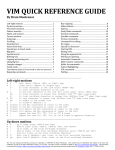
IRIS Rear Panel Connections
The diagram below illustrates the relevant rear panel ports and connections on the IRIS.
Autoswitching
110/230V Power
Supply
Coax Transmit
Port
100 Mbps
Ethernet Uplink
Port
Coax Receive
Port
UPLINK
RX2
RX1
TX
CONSOLE
Power Supply
Cooling Fan
Male DB9 Serial
Console Port
PWR
ACT
RF ON
Air
Ventilation
Figure 1 IRIS Rear Panel
IRIS Rear Panel consists of the following connectors and labels
1.
2.
3.
4.
5.
6.
7.
Auto switching 110V/230V power supply connector
Female ‘F’ Connector for coax Transmit
Female ‘F’ connector for coax Receive channel 1
Female ‘F’ connector for coax Receive channel 2 (for DC1200 models only)
Uplink Ethernet RJ-45 port
Serial console port
LEDs:
• Power (PWR) LED: Green when the power is connected and the system power up.
• Activity (ACT) LED: Amber/Yellow LED Blinks indicating Up Stream data transfer
is active.
• RF ON LED: Green LED is lit when the Up converter is successfully powered on.
8. Rack mounting Ears (not shown): IRIS chassis has a provision for mounting the chassis
backwards if customer desires.
The above-mentioned connectors are mainly required for configuration and operation of IRIS.
The rear panel may contain other connectors for future features and the user should currently
ignore them.
Coaxial Networks, Inc.
Page 13 of 60
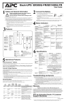
IRIS Front Panel
The diagram below illustrates the front panel controls of the IRIS.
SYSTEM
FANS, (DON'T
BLOCK WHILE
MOUNTING)
IRIS
Cable Modem Termination System
RACK MOUNTING BRACES
(REMOVALBLE)
Figure 2 IRIS Front Panel
The front panel has no indicators or controls.
1. Removable rack mounting braces for 19” rack mounting.
2. Intake openings for the system cooling fans for the IRIS chassis
Both Front panel and rear panel have vents for system fan, care should be taken that these vents
are not blocked during installation.
Mounting the IRIS Unit
The IRIS system can be mounted on a 19” Floor mounted Rack or 19” Wall Mount Rack with
other equipment. In the absence of a 19” rack, you can mount the IRIS unit flat on the wall with
the same mounting brackets supplied with the unit. The screws are provided to attach these braces
to the chassis. However you will need to provide appropriate screws to secure the chassis to the
wall. If you have a dry wall, recommended screws are hollow wall anchor screws. Always check
your local code for compliance.
Mounting on standard 19” Rack with IRIS connectors in the Front
Use the supplied screws to attach the mounting brackets to the sides of the unit in the front for
mounting IRIS on a 19” rack. Your rack supplier usually supplies the screws required for
mounting.
Mounting on standard 19” Rack with IRIS connectors in the Rear
Use the supplied screws to attach the mounting brackets to the sides of the unit in the rear for
mounting IRIS on a 19” rack. Your rack supplier usually supplies the screws required for
mounting.
Coaxial Networks, Inc.
Page 14 of 60
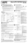
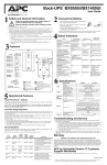
Mounting Flat on Wall
To mount the IRIS chassis for flat wall mount use the supplied rack mounting braces and attach
them to the holes in the middle of chassis using the same screws.
Holes for Rear
Mounting
IR I
SF
Holes for Flat wall
Mounting
ron
t
Holes for Front Mounting
Figure 3 Attaching mounting braces for flat wall mount
You will need appropriate screws to secure the chassis to the wall. If you have a dry wall,
recommended screws are hollow wall anchor screws. Always check your local code for
compliance. Refer to the diagram for positioning the chassis so that sufficient air can flow in and
out of the chassis.
RACK MOUNT
BRACES
WALL ANCHOR
SCREWS, (Not
Supplied)
CHASSIS
FRONT
CHASSIS REAR
AIR
FLOW
AIR
FLOW
IRIS CHASSIS TOP
MOUNTING IRIS FLAT ON WALL
Figure 4 Flat Wall Mount
Do not mount the chassis with the chassis front of rear facing upwards. Falling debris from the
ceiling can damage the systems fans. Make sure you have sufficient room around the air ducts for
Coaxial Networks, Inc.
Page 15 of 60
air to flow in and out of the system. Sufficient airflow will guarantee peek performance and
longevity of the IRIS system.
Coaxial Networks, Inc.
Page 16 of 60
Setup
Connecting Your IRIS DC1100
1. Place your IRIS DC1100 in a location where it will be well ventilated. Do not stack it
with other devices or place it on carpet.
2. Connect your WAN equipment Ethernet port with CAT5 cross over cable to IRIS
DC1100 Ethernet Port. If connecting to a hub or switch use a CAT5 straight through
cable.
3. For coaxial connections determine the model number of the IRIS unit.
The following models come with integrated fully agile 256 QAM DOCSIS Upconverter.
DC1100/DC1200/DC1400
The following models do not include an integrated upconverter.
DC1100X/DC1200X/DC1400X
You will have to connect the IF out from IRIS to a 256 QAM DOCSIS upconverter,
before cable modems will be able to connect to IRIS.
Refer to the chapter 3 for diagrams detailing these connections.
Checking Conditions Prior to System Startup
Check the following conditions before you start your gateway:
All network interface cables are connected.
The power cable is connected and secured.
The console terminal is connected and powered on.
Starting the System
After installing the IRIS gateway and connecting cables, start the router as follows:
Insert the power cable at the rear of the IRIS chassis. The green Power LED on the rear
panel will light up.
Listen for the fans; you should immediately hear them operating.
AC T ACT
LNK1
P
Configuring Your IRISDC1100
Coaxial Networks, Inc.
Page 17 of 60
Coaxial Cable Specifications
The coaxial cable used to connect the IRIS DC1100 series universal broadband routers at the
Headend should be very high-quality cable. Coaxial recommends that you use a Headend-grade
coaxial cable or a quad-shield coaxial cable with a minimum of 60% + 40% braid and double foil
insulation to connect the cable modem cards to the HFC network. The center conductor must be
straight and extend 1/8 inch (3.2 mm) beyond the end of the connector, and the connector should
be securely crimped to the cable. The following cables are recommended:
• RG-6 — Standard 75 Ohm
• RG-6/U — Dual or Quad Shielded 75 Ohm
Note
The consistent use of RG-6 or RG-6/U cable is preferred to connect the cable interface to the
HFC network. If you connect an RG-6 cable to a cable interface that was previously connected
using RG-6 cable, the difference in the center connector diameter might cause intermittent
connectivity loss. If you use different types of coaxial cable, the following problems can appear:
Co-channel interference—If signals at the same frequency are carried on long, parallel runs
of coaxial cable, interference can occur between the signals. Higher quality cable helps to
prevent this with better shielding. Co-channel interference is seen as hum or patterns in
analog video channels and intermittent data loss in digital channels.
Damage to the product —Cable interface card connectors are designed for RG-6 cable and
connectors. Larger cables can damage the connectors.
Coaxial Networks, Inc.
Page 18 of 60
Connections
Cable Network Diagram
IRIS Connections with Integrated Upconverter
IRIS model numbers DC1100 and DC1100C come with an integrated upconverter. The following
diagram illustrates the connections.
UPLINK
Diplexer
RX1
TX
CONSOLE
PWR
ACT
RF ON
IRIS Rear Panel
Diplexer
TO DISTRIBUTION
Figure 5 Connections with Integrated Upconverter
)
If in your headend you are using passive equipment such as combiner which does
not allow return signals, make sure that the connections are made in such a manner
that return signals are not affected by such equipment.
IRIS Connections with an external Upconverter
IRIS model numbers DC1100X and DC1100CX come without an integrated upconverter. You
will need an external DOCSIS upconverter to connect IRIS to your cable system. The following
diagram illustrates the connections when using IRIS with an external upconverter.
Coaxial Networks, Inc.
Page 19 of 60
UPLINK
Diplexer RX1
TX
CONSOLE
PWR ACT
RF ON
IRIS Rear Panel
RF OUT
IF IN
Upconverter Rear Panel
Diplexer
TO DISTRIBUTION
Figure 6 Connections with an external Upconverter
IRIS Uplink Connection
IRIS Uplink port is a 10/100 Ethernet port, which has to be connected to back office network
switch or the uplink device such as satellite or DSL modem. When connecting to a switch a
straight Cat5 Ethernet cable will be required. When connecting to a DSL modem or satellite
modem you might need to use an orange colored cross over cable.
The link light on the IRIS Uplink port will light up when you have used the right cable required
to connect to the switch or the uplink device.
UPLINK
Diplexer
CONSOLE
RX1
PWR
TX
RFON
ACT
IRIS Rear Panel
CAT5
Connect to Switch or
Uplink Device
Figure 7 IRIS Uplink Connection
Coaxial Networks, Inc.
Page 20 of 60
Configuration
Configuring IRIS
All IRIS systems can operate in Bridge or Routing mode with NAT enabled on the cable
interface. At the time of shipping the system IRIS is configured to work in the routing mode with
NAT enabled on the cable interface.
When NAT is enabled IRIS routes packets from its cable interface to the Ethernet interface and
vice-versa. The diagram below represents the IP network topology with such configuration.
The cable interface is defined as “en1” interface and the Ethernet interface is defined as “en2”
Cable Interface
en1
CM Network
IP: 10.1.1.1
Netmask: 255.255.255.0
Ethernet Interface
en2
IRIS DC1100
IP: 192.168.21.1
Netmask: 255.255.255.0
CPE Network
IP:10.71.0.1
Netmask: 255.255.252.0
Logging into IRIS
To configure IRIS you will have to login to IRIS either using the serial console port or over the
network using the web interface or telnet program.
Connecting from Ethernet interface
You should have already connected the IRIS uplink Ethernet interface to a switch or to a PC
using a cross over Ethernet cable. Configure your PC to have static IP address such as
192.168.21.100 and subnet mask 255.255.255.0. Make sure no other device on this network has
this IP address.
Coaxial Networks, Inc.
Page 21 of 60
Connecting using Web Interface
Start your Internet browser and point it to
http://192.168.21.1:2380. You will be prompted by
the “IRIS Admin” login window. Please enter the
User name and Password to authenticate. All IRIS
systems ship with default user name “iris” and
password “123456”. IRIS Setup home page will
appear in your browser as shown in Figure 9.
Figure 8 Web Login
Figure 9 Setup home page
Coaxial Networks, Inc.
Page 22 of 60
The Web interface can be used to configure the following parameters
1.
2.
3.
4.
5.
6.
7.
8.
TCP/IP parameters
IRIS Operational mode
Web login password
Cable modem subscription
Cable modem tftp configuration file generation for QOS
Downstream channel, QAM mode and Output power level
Upstream frequency for each channel
Report cable modem status
Configuring TCP/IP parameters
To configure TCP/IP parameter for IRIS or to set its operational mode click on the “Network” on
the left hand side navigational menu. Once selected the IRIS Network Setup screen appears on
the right hand side as shown in Figure 10.
Figure 10 IRIS Configuration Page
Coaxial Networks, Inc.
Page 23 of 60
Configuring IRIS in Router mode
All IRIS systems ship with operational mode set to “router”. In router mode the cable interface is
configured with a private interface and all cabled modems and CPEs attached to the cable
modems are automatically assigned IP addresses from this private addressing scheme.
You will need to configure the “Uplink Interface” or the Ethernet Interface with the ISP provided
configuration parameters. For the “Uplink Interface” enter the following
−
−
−
−
−
)
IP address
Netmask
Gateway
DNS Server
Domain Name
Do not change the “Cable CM Interface” or the “Cable CPE Interface” address.
Changing this will require you to edit the DHCP server configuration file manually.
You should change this address only if you wish to do so and know how to manually
program a dhcpd.conf file. Future releases of IRIS firmware will provide graphical
user interface to edit the DHCP server configuration files.
After entering these, click the “Save” button. For changes to take effect select ‘Reboot” from the
left hand side navigation bar.
Figure 11 Save and reboot
Confirm the reboot with selecting the “Reboot” button. After the reboot you should be able to
reach the “uplink” port of IRIS using the new IP address.
Coaxial Networks, Inc.
Page 24 of 60
Configuring IRIS in Bridge mode
To configure IRIS in “bridge” mode select “Network” from the navigation menu bar. If you
configure IRIS in bridge mode, you will need to use an external provisioning server that can
provide all the required server functionality which includes DHCP server, TFTP server and TOD
server.
Figure 12 Network Setup
You will also need to configure you provisioning server so that it can allocate IP addresses to
CPE devices that are behind the cable modems. CNI provides a provisioning server called
‘XFIRE’ to achieve this functionality.
If you are planning to use multiple IRIS in your cable plant you should put IRIS in bridge mode
and use an external provisioning server. The detail setup of such a provisioning server is
beyond the scope of this document. Customers should contact CNI professional services to
get further information and training on such topics.
Click the “IRIS Mode” drop down box to select “bridge”
Coaxial Networks, Inc.
Page 25 of 60
Figure 13 Bridge mode setup
This will change the IRIS Setup screen so that the system can be configured in the bridge mode.
In bridge mode IRIS only has one interface, which is the “cable” interface. IRIS then forward all
traffic from the HFC side to the Ethernet side.
If you are planning to use the DHCP server available on IRIS do not change “Cable CM
Interface” address. If you change this address and plan to use DHCP server on IRIS to assign IP
addresses to the cable modems make sure that the DHCP configuration file has appropriately
been updated.
Using the Alias Interface you can assign another IP address configuration to IRIS; this could be
useful if you wish to assign a public IP address to IRIS.
Coaxial Networks, Inc.
Page 26 of 60
Figure 14 Bridge Mode Configuration
Coaxial Networks, Inc.
Page 27 of 60
Configuring Downstream RF Settings
DOCSIS protocol utilizes an available channel to send downstream signal for data
communications. Depending upon the frequency plan NTSC or PAL, IRIS automatically provides
you the channel number and the center frequency in a drop down menu.
Figure 15 Downstream RF Settings
Using the “Center frequency with channel number” select the channel that you wish to use to
send downstream signal. This channel should not be used to send any video signal.
Using the “RF Power” setting you can adjust the output level of the downstream signal. If you
wish to adjust output power levels beyond the range you have to use outside attenuators. Digitally
modulated signal levels are usually 10 to 12 dB less than the analog signal levels for the adjacent
carriers.
256 and 64 QAM modulation is used for downstream communication. 256 QAM requires a much
cleaner plant and channel. For noisier cable plants it is recommended to use 64 QAM for
downstream. Using the ‘Modulation scheme’ select the appropriate downstream modulation plan.
After making the selection click the “Save” button to apply these changes. Center frequency and
RF power changes do not require system to be rebooted. Changing the downstream modulation
scheme requires a system restart.
Coaxial Networks, Inc.
Page 28 of 60
Configuring Upstream RF Settings
DOCSIS protocol utilizes a separate upstream frequency to provide upstream data
communication back from the cable modem. Your cable plant has to be two way ready or return
passing to provide high speed data communication over cable. The North American plan uses up
to a 3.2MHz wide channel in the 5-42MHz frequency range. The European plan uses up to a 3.2
MHz wide channel in the 5-65MHz frequency range. For upstream communications DOCSIS
provide QPSK or 16QAM modulation schemes. QPSK modulation profiles are much tolerant to
noise. 16QAM modulation profiles require very clean cable plants and signal to noise ratios.
Figure 16 Upstream RF Settings
Depending upon the IRIS model you have, the Upstream RF Settings screen will have the number
of channels. For a DC1100 the screen will only have Channel 1, for DC1200 the screen will show
Channel 1 and Channel 2.
In the Frequency section for each channel type in the desired upstream center frequency you wish
to use. From the available modulation profiles select the modulation profile you wish to use.
Various modulation profiles for both 16QAM and QPSK are provided in the system.
If your system has more than one upstream channel make sure that there frequency values are
separated by a sufficient buffer or else they will interfere with each other resulting in loss of cable
modems.
After you have made the right selection, click on “Save” and the changes will apply after the
system is restarted.
Coaxial Networks, Inc.
Page 29 of 60
Creating Class of Service Profiles
DOCSIS based data networks allow each cable modem to be associated to a class of service. This
class of service configuration is downloaded by the cable modem during registration process
using TFTP protocol.
IRIS provides a user interface using which you can enter different values for a cable modem
configuration file and then save these settings to class of service. These classes of services
profiles are then available to you in the “CM Subscription” section of IRIS configuration.
Figure 17 Class of Service Creation
When creating cable modem configuration files which specify the class of service that the cable
modem and CPEs behind them will be receiving, you can specify a different downstream channel
that the cable modem should resynchronize to after registering with this IRIS. You can also
specify which upstream channel a cable modem should register on. The Upstream channel can be
used to tie a particular class of service to a particular upstream channel. This setting is useful if
you have IRIS DC1200 or IRIS DC1400 models.
The “Net Access Enable” setting specifies if CPEs behind a cable modem configuration that
downloads this configuration file will be able to get access o the network or not.
The remaining settings specify the various parameters for class of service. Chose a “SVC Class
ID” by which you want to identify this service. This value can be any integer value and is used
for identification purposes only.
In the “MAX DS Rate…” specify the rate at which cable modems can download data. For
example if you wish to provide a 512bps data rate, you would enter 512000 in this field.
Coaxial Networks, Inc.
Page 30 of 60
In the “US Priority” specify the priority that you wish to assign traffic coming from this cable
modem in the upstream direction. IRIS supports 1 to 7 upstream priority classifications, 1 being
the highest.
In the “Guaranteed US Rate” specify upstream data rate which you wish to guarantee for each
cable modem. For example for voice traffic a guaranteed upstream rate of 64000 is
recommended.
In the “Configuration File name” specify the name you would wish to give this type service, for
example “business” or “residential”.
In the “Maximum CPE per Cable Modem” select the number of CPEs you wish to allow
behind the cable modem.
After entering all the values, make sure that these are the settings you wish to create this class of
service with and the click the “Generate Configuration file”
Remember that any protocol has overhead and your customers will see slightly less value if they
do a speed test. Usually the speed test program do not account for the overhead of transferring IP
packets.
In the ‘MAX US Rate…” specify the rate at which cable modems can upload data. For example
if you wish to provide a 128Kbps data rate, you would enter 128000 in this field.
IRIS implements a Class Based Queue and Round Robin allocation strategies for downstream
rate regulation. In Round Robin packets are put on a first in first out queue and as long as
bandwidth is available it will be given to the client requesting it.
If you wish to rate limit a customer to the bandwidth he is subscribed for even though there is
bandwidth available you have to enable the Class Based Queuing. By default round robin is
enabled.
Coaxial Networks, Inc.
Page 31 of 60
Controlling Cable Modem Access
IRIS can allow all or selectively allow cable modems connected to your cable network to gain
access to the Internet.
)
By default IRIS is configured such that all modems that are connected on
your cable plant can gain access to the Internet.
To enable conditional access to certain we need to enable conditional access and then add the
MAC addresses of the cable modems. Once it has been done only cable modems with these MAC
addresses can register with IRIS. Other cable modems will not register and PCs behind these
cable modems will not be able to connect to the Internet.
Enabling conditional access
Using your browser connect to IRIS configuration interface. Select “CM Subscription” under
Advanced options.
To enable conditional access to the modems select the “Subscribe selected cable modems” and
then select “Save”. This change comes into effect after you restart IRIS.
Adding Cable Modems
After you have enabled conditional access for cable modems and restarted the system, you should
see the list of cable modems that have been subscribed. All remaining modems that have not been
subscribed but have tried to connect to the IRIS will show up in the “unsubscribed modems” list.
You can move cable modems that show up in the “unsubscribed modems” list to the “subscribed
modems” list. While subscribing modems you can assign a unit number that can be used to define
Coaxial Networks, Inc.
Page 32 of 60
the location of each cable modem and also associate the cable modem to one of the class of
service profiles you have created. If you have not created any class of service profiles, create a
class of service using the “CM configuration” option.
A cable modem that had yet not been connected to the cable network will not show up in the
“unsubscribed modems” list. If you wish to subscribe such a cable modem before it is connected
to the cable network you should use the ‘Quick Subscription” option to enter the Mac address of
the cable modem in the show format manually and click on the “Subscribe” button.
Figure 18 Cable Modem Subscription
Saving Cable Modems List
After each subscription please click the “Save” button so that the cable modem configuration is
updated correctly in the system.
Coaxial Networks, Inc.
Page 33 of 60
You will need to save the “subscribed modems” list so that the same is available after a system
restart. Press the “Save” button to save or update the “subscribed modems” list to the flash
memory of IRIS.
Coaxial Networks, Inc.
Page 34 of 60
IRIS CLI interface using Telnet
IRIS also provides a CLI interface for certain advanced configuration and diagnostics. You will
need a PC to connect using telnet. You should be able to connect to IRIS from the HFC side if
you have successfully been able to bring up a cable modem. The easiest way to connect to IRIS is
from the Ethernet interface of IRIS.
Connecting from the cable interface
If you have connected a cable modem to the cable network you can connect to IRIS using a PC
connected to the cable modem. Make sure the cable modem’s “cable” LED is steady which
indicates that the cable modem is configured correctly and is up and running. If the “cable” LED
is either off or still blinking the cable modem is not up yet, use the “Connecting from Ethernet
interface” or “Connecting using serial console” methods.
Set your PC’s Ethernet interface to be configured using dynamic host control protocol or DHCP.
As soon as your PC is connected to the Ethernet port of the cable modem it will be assigned an IP
address with the “10.71.0.X” domain.
Telnet to IRIS
You can now telnet from Windows Start Menu/Run option by typing
“telnet 10.71.0.1” and selecting OK button. You will be greeted with the following
messages and a “login” prompt in the telnet window.
Figure 19 Telnet login prompt
Connecting from serial console
Coaxial Networks, Inc.
Page 35 of 60
Using a serial (RS232) 9 pin null modem cable connect your PC’s serial port to the serial console
port of IRIS. Now you can use tools such as “HyperTerminal” in Windows to connect to IRIS.
The settings for the serial console port of IRIS are
Baud Rate: 57600
Data Bits: 8
Parity: None
Stop Bits: 1
Flow Control: None
After successfully connecting to the console port you should see the IRIS “login” prompt.
Logging In
At the login prompt, type the username as “iris” and hit enter. At the “password” prompt type
“123456” or the new password if you have already changed the default password.
After you have successfully logged in you are greeted by the “IRIS>” prompt.
Figure 20 IRIS CLI prompt
“help” command
You can type “?” or “help” on the IRIS prompt to see the list of CLI commands available.
You can type “?” or “help” on the IRIS prompt to see the list of CLI commands available.
IRIS>?
(h)elp .........................
count ..........................
rcount .........................
ver ............................
Coaxial Networks, Inc.
list usage
print packet counters
clear packet counters
display IRIS version
Page 36 of 60
psid............................
preg............................
pcpe............................
config_cm <ifile> <ofile> ......
(q)uit .........................
system .........................
reboot .........................
shutdown .......................
!...............................
tty.............................
passwd..........................
upcon <cmd> ....................
setupl .........................
setif <if> <ip> <netmask> ......
showif [if] ....................
dhcp <cmd> .....................
bridge [on/off] ................
addcm <mac_address> [comment] ..
delcm <mac_address> ............
savecm .........................
psub ...........................
punsub .........................
print MacAddress to Sid map
print CM registration status
print CM and associated CPE
generate CM config file
quit command interpreter
go to the system prompt
restart the system
shutdown the system
repeat last command
displays the terminal name
changes password for iris
upconveter config command, upcon ? for list
setup uplink (en2) IP network parameters
sets interface ip address and netmask
show interface parameters, en1, en2
dhcp server command, dhcp ? for list
Enable or disable briding mode for IRIS
Add CM to subscribed list
Delete CM from subscribed list
Save subscribed CM list
Print subscribed CM list
Print unsubscribed CM list
Figure 21 List of CLI commands
“preg” or ”preg verbose” command
The “preg” command displays you a list of MAC addresses of cable modems that have
communicated to IRIS, their SID (service identifier) and the current registered state.
IRIS>preg
Registered CMs
------------------------------------------------------------------------------MAC
PSID
USID
STATUS
------------------------------------------------------------------------------00:0b:06:9f:a7:fe
00:10:95:1b:e1:c5
00:30:eb:bc:0c:a5
00:90:83:8c:58:23
00:e0:ca:00:c1:9c
0x0002
0x0001
0x0004
0x0003
0x0005
0x01
0x01
0x01
0x01
0x01
Yes
Yes
Yes
Yes
Yes
Total(5), Yes(5) No(0)
Unsubscribed CMs
------------------------------------------------------------------------------Total(0)
Figure 22 List of registered cable modems
“psid” command
The “psid” command displays you a list of MAC addresses of cable modems or PCs connected to
the cable modems. Each cable modem and PCs connected to them will have unique MAC address
but same SID or service identifier.
IRIS>psid
MAC address to SID map:
------------------------------------------------------------------------------MAC
SID
Coaxial Networks, Inc.
Page 37 of 60
------------------------------------------------------------------------------00:0b:00:02:01:0a
00:0b:06:9f:a7:fe
00:10:5a:d0:1d:cd
00:10:95:1b:e1:c5
00:10:b5:3e:56:a2
00:30:eb:bc:0c:a5
00:90:83:8c:58:23
00:e0:ca:00:c1:9c
ff:ff:ff:ff:ff:ff
0x0002
0x0002
0x0001
0x0001
0x0002
0x0004
0x0003
0x0005
0x16383
Total:(9)
Figure 23 List of SID and their MAC addresses
“pcpe” command
The “pcpe” command displays you a list of MAC addresses of cable modems that have
communicated to IRIS, their SID (service identifier) and the current registered state. It also
displays the MAC addresses of the CPE’s connected to each registers cable modems.
IRIS>pcpe
Registered CMs
------------------------------------------------------------------------------MAC
PSID
USID
STATUS
------------------------------------------------------------------------------00:0b:06:9f:a7:fe
00:0b:00:02:01:0a
00:10:b5:3e:56:a2
00:10:95:1b:e1:c5
00:10:5a:d0:1d:cd
00:30:eb:bc:0c:a5
00:90:83:8c:58:23
00:e0:ca:00:c1:9c
0x0002
0x01
Yes
0x0001
0x01
Yes
0x0004
0x0003
0x0005
0x01
0x01
0x01
Yes
Yes
Yes
Total(5), Yes(5) No(0)
Unsubscribed CMs
------------------------------------------------------------------------------Total(0)
Figure 24 List of CPEs connected to the CMs
“config_cm” command
The “config_cm” is used to compile and create cable modem configuration file that the cable
modems download from IRIS during the registration process. The cable modem configuration file
has important operational parameters including the data rates that the cable modem will be using
for upstream and downstream traffic.
The cable modem configuration files should be located in the “/tftpboot” directory after
compilation and the “/etc/dhcpd.conf” specifies the name of the configuration file to the
cable modem during it downloads IP parameters from the Dhcp server.
“count” command
Coaxial Networks, Inc.
Page 38 of 60
The “count” command displays the number of Interrupts, Packets received, Packets Transmitted
and Errors on the cable interface of IRIS.
“rcount” command
Resets the values of the above mentioned counters.
“ver” command
Displays the version of IRIS and IRIS CLI.
“reboot” command
Restarts the system.
“shutdown” command
Shuts down the system, so that it can be powered off safely.
“system” command
Takes you to the QNX system prompt from the IRIS CLI. To return back to the IRIS CLI, type
“exit” at the system prompt.
“quit” command
The quit command exits the IRIS CLI. On a telnet connection it would close your telnet session.
On the serial console, it will log out and display the login prompt gain.
“!” command
Repeats the last command that you had typed.
“tty” command
Displays the name of the terminal you are currently connected on.
“passwd” command
Prompts to change the “iris” password. You should change the “iris” password once you have
received the system. Make a note of the password in a safe place so that you do not forget the
password.
Coaxial Networks, Inc.
Page 39 of 60
“upcon” command
Using the “upcon” command you can program and check status of the integrated upconverter in
the IRIS DC1100 and IRIS DC1100C.
Upcon FL <frequency>
Load upconverter with the desired frequency, output is muted and then unmuted.
For example to set the downstream frequency to 369MHz, at the “IRIS>” prompt type
upcon fl 369000000
Consult chapter on “Channel Frequency Chart” to find center frequency of a TV channel that
you wish to use.
Upcon FLI <frequency>
Loads upconverter with the desired frequency without affecting the output.
See the Upcon FL command for example.
Upcon AI <IF attenuator setting>
Load the desired value for the IF Attenuator. User should use the “IAE” and let the upconverter
chose the desired attenuation automatically.
Upcon IAS <high limit> <low limit>
Set the IF IF ALC high and low limit
Upcon IAD
Disable IF ALC.
Upcon IAE
Enable IF ALC. This is the default setting and should not be changed.
Upcon ITS
IF Threshold Set
Upcon ITD
IF Threshold Disable
Upcon ITE
IF Threshold Enable
Upcon MOD
Disable upconverter output.
Upcon MOE
Enable upconverter output.
Upcon AR <number of 0.1dB steps>
Coaxial Networks, Inc.
Page 40 of 60
Loads the RF Attenuator with desired value.
Upcon RAS <high limit> <low limit>
Sets high and low values for RF ALC.
Upcon RAD
Disable RF ALC.
Upcon RAE
Enable RF ALC. This is the default setting.
Upcon RLS <RF Power limit>
Sets the RF power limit.
Upcon RPS <RF Power level>
Sets the RF Power.
Upcon RTD
Disable the RF Threshold.
Upcon RTE
Enable the RF Threshold.
Upcon RTS <high limit> <low limit>
Sets the desired value for the RF Threshold.
Upcon SC
Displays the current operating parameters for the upconverter.
Upcon SP
Displaces the IF and RF power coming to and from the upconverter module.
Coaxial Networks, Inc.
Page 41 of 60
This page intentionally left blank
Coaxial Networks, Inc.
Page 42 of 60
Application Notes
Network traffic between cable clients
By default IRIS does not allow traffic between CPEs behind cable modems on the same IRIS. To
enable this you have to turn the “NetLoopbackMode” setting in iris.txt file to “1”.
Edit the “iris.txt” file from the system prompt and then change the above seeting to
NetLoopbackMode = 1
Save the file and restart IRIS.
Allowing PPPoE traffic across IRIS
By default IRIS is configured to forward Ethernet packets of IP protocol type only. If you wish to
offer PPPoE services to your customers, you have to configure IRIS so that PPPoE protocol is
forwarded across IRIS. This configuration applies if you are operating IRIS in bridge mode.
Edit the “iris.txt” file from the system prompt and then under the
“BEGIN_NetProtocolType“ section add the following lines which specify the PPPoE
Ethernet packet type
BEGIN_NetProtocolType
TypeField1 = 0x81
TypeField2 = 0
TypeLength = 1
END_NetProtocolType
Make sure you do not remove the default forwading for IP Ethernet packet types.
BEGIN_NetProtocolType
TypeField1 = 8
TypeField2 = 0
TypeLength = 1
END_NetProtocolType
// default = 8 (IP)
// default = 0 (ALL)
// default = 1
Save the file and restart IRIS.
Static IP Mapping
When IRIS is operating in Router mode, some ISPs will like to reserve a publicly routable IP
address for a specific CPE behind the Network Address translation. Using this feature IRIS will
then create a one to one mapping between the public IP address and the private IP address. This
feature of NAT is called BIMAP.
Coaxial Networks, Inc.
Page 43 of 60
To create a BIMAP you will need to know the MAC address of the CPE. To obtain this you can
Telnet to IRIS and issue the "pcpe" command find the cable modem that the end user has,
attached you will see his CPE Mac address.
Assigning a reserved IP address to the CPE.
Edit the /etc/dhcpd.conf file and add a "host" entry for the MAC address of the CPE with a
Reserved IP address in the "#CPE Network" subnet
host user1 {
hardware ethernet 00:12:17:4C:9b:21;
fixed-address 10.71.0.2 ;
}
Save the file and restart the DHCP server using the following commands
# slay -f dhcpd <ENTER>
# dhcpd en1 <ENTER>
Assigning additional IP addresses to the uplink Interface
From system prompt edit the "netstart.user" file and add the following line
/usr/ucb/ifconfig en2 alias <ip-address> netmask <netmask>
Make sure you put the <ip-address> and <netmask> that you have from your service
provider.
This command will configure IRIS "en2" or uplink interface with an additional IP address that
will be used to create a BIMAP. Save the file and exit to system prompt.
Creating a BIMAP between the public IP address and the private IP address
From system prompt edit the startnat file and at the end of the line before the
"EOF" command
bimap en2 <internal-ip-address>/32 -> <public-ip-address>/32
Replace <internal-ip-address> with the internal IP address that you have reserved in the
dhcpd.conf file in step 1. Replace <public-ip-address> with the external Ip address that was
assigned to the en2 port in step 2. Save the file and exit to system prompt. Restart the system to
make the changes.
Coaxial Networks, Inc.
Page 44 of 60
Channel Frequency Chart
NTSC Channel Frequency Chart in MHz (DOCSIS)
Channel Number
Bandwidth
Coaxial Networks, Inc.
Center Frequency
FM
88.0 - 108.0
A-5 - 95
90.0 - 96.0
93.00
A-4 - 96
96.0 - 102.0
99.00
A-3 - 97
102.0 - 108.0
105.00
A-2 - 98
108.0 - 114.0
111.00
A-1 - 99
114.0 - 120.0
117.00
A - 14
120.0 - 126.0
123.00
B - 15
126.0 - 132.0
129.00
C - 16
132.0 - 138.0
135.00
D - 17
138.0 - 144.0
141.00
E - 18
144.0 - 150.0
147.00
F - 19
150.0 - 156.0
153.00
G - 20
156.0 - 162.0
159.00
H - 21
162.0 - 168.0
165.00
I - 22
168.0 - 174.0
171.00
7-7
174.0 - 180.0
177.00
8-8
180.0 - 186.0
183.00
9-9
186.0 - 192.0
189.00
10 - 10
192.0 - 198.0
195.00
11 - 11
198.0 - 204.0
201.00
12 - 12
204.0 - 210.0
207.00
13 - 13
210.0 - 216.0
213.00
J - 23
216.0 - 222.0
219.00
K - 24
222.0 - 228.0
225.00
L - 25
228.0 - 234.0
231.00
M - 26
234.0 - 240.0
237.00
N - 27
240.0 - 246.0
243.00
O - 28
246.0 - 252.0
249.00
P - 29
252.0 - 258.0
255.00
Q - 30
258.0 - 264.0
261.00
R - 31
264.0 - 270.0
267.00
S - 32
270.0 - 276.0
273.00
T - 33
276.0 - 282.0
279.00
U - 34
282.0 - 288.0
285.00
Page 45 of 60
Coaxial Networks, Inc.
V - 35
288.0 - 294.0
291.00
W - 36
294.0 - 300.0
297.00
AA - 37
300.0 - 306.0
303.00
BB - 38
306.0 - 312.0
309.00
CC - 39
312.0 - 318.0
315.00
DD - 40
318.0 - 324.0
321.00
EE - 41
324.0 - 330.0
327.00
FF - 42
330.0 - 336.0
333.00
GG - 43
336.0 - 342.0
339.00
HH - 44
342.0 - 348.0
345.00
II - 45
348.0 - 354.0
351.00
JJ - 46
354.0 - 360.0
357.00
KK - 47
360.0 - 366.0
363.00
LL - 48
366.0 - 372.0
369.00
MM - 49
372.0 - 378.0
375.00
NN - 50
378.0 - 384.0
381.00
OO - 51
384.0 - 390.0
387.00
PP - 52
390.0 - 396.0
393.00
QQ - 53
396.0 - 402.0
399.00
RR - 54
402.0 - 408.0
405.00
SS - 55
408.0 - 414.0
411.00
TT - 56
414.0 - 420.0
417.00
UU - 57
420.0 - 426.0
423.00
VV - 58
426.0 - 432.0
429.00
WW - 59
432.0 - 438.0
435.00
XX - 60
438.0 - 444.0
441.00
YY - 61
444.0 - 450.0
447.00
ZZ - 62
450.0 - 456.0
453.00
AAA - 63
456.0 - 462.0
459.00
BBB - 64
462.0 - 468.0
465.00
CCC - 65
468.0 - 474.0
471.00
DDD - 66
474.0 - 480.0
477.00
EEE - 67
480.0 - 486.0
483.00
FFF - 68
486.0 - 492.0
489.00
GGG - 69
492.0 - 498.0
495.00
HHH - 70
498.0 - 504.0
501.00
III - 71
504.0 - 510.0
507.00
JJJ - 72
510.0 - 516.0
513.00
KKK - 73
516.0 - 522.0
519.00
LLL - 74
522.0 - 528.0
525.00
MMM - 75
528.0 - 534.0
531.00
Page 46 of 60
Coaxial Networks, Inc.
NNN - 76
534.0 - 540.0
537.00
OOO - 77
540.0 - 546.0
543.00
PPP - 78
546.0 - 552.0
549.00
QQQ - 79
552.0 - 558.0
555.00
RRR - 80
558.0 - 564.0
561.00
SSS - 81
564.0 - 570.0
567.00
TTT - 82
570.0 - 576.0
573.00
UUU - 83
576.0 - 582.0
579.00
VVV - 84
582.0 - 588.0
585.00
WWW - 85
588.0 - 594.0
591.00
XXX 86
594.0 - 600.0
597.00
YYY - 87
600.0 - 606.0
603.00
ZZZ - 88
606.0 - 612.0
609.00
89 - 89
612.0 - 618.0
615.00
90 - 90
618.0 - 624.0
621.00
91 - 91
624.0 - 630.0
627.00
92 - 92
630.0 - 636.0
633.00
93 - 93
636.0 - 642.0
639.00
94 - 94
642.0 - 648.0
645.00
100 - 100
648.0 - 654.0
651.00
101 - 101
654.0 - 660.0
657.00
102 - 102
660.0 - 666.0
663.00
103 - 103
666.0 - 672.0
669.00
104 - 104
672.0 - 678.0
675.00
105 - 105
678.0 - 684.0
681.00
106 - 106
684.0 - 690.0
687.00
107 - 107
690.0 - 696.0
693.00
108 - 108
696.0 - 702.0
699.00
109 - 109
702.0 - 708.0
705.00
110 - 110
708.0 - 714.0
711.00
111 - 111
714.0 - 720.0
717.00
112 - 112
720.0 - 726.0
723.00
113 - 113
726.0 - 732.0
729.00
114 - 114
732.0 - 738.0
735.00
115 - 115
738.0 - 744.0
741.00
116 - 116
744.0 - 750.0
747.00
117 - 117
750.0 - 756.0
751.00
118 - 118
756.0 - 762.0
759.00
119 - 119
762.0 - 768.0
765.00
120 - 120
768.0 - 674.0
771.00
121 - 121
774.0 - 780.0
777.00
Page 47 of 60
Coaxial Networks, Inc.
122 - 122
780.0 - 786.0
783.00
123 - 123
786.0 - 792.0
789.00
124 - 124
792.0 - 798.0
795.00
125 - 125
798.0 - 804.0
801.00
126 - 126
804.0 - 810.0
807.00
127 - 127
810.0 - 816.0
813.00
128 - 128
816.0 - 822.0
819.00
129 - 129
822.0 - 828.0
825.00
130 - 130
828.0 - 834.0
831.00
131 - 131
834.0 - 840.0
837.00
132 - 132
840.0 - 846.0
843.00
133 - 133
846.0 - 852.0
847.00
Page 48 of 60
PAL Frequency Allocation (EuroDOCSIS)
System L
France
System K1
France
Overseas
System I RSA
System I
Ireland
System D OIRT
System D PRC Center
Frequency
6
4
4
RVI
ID
7
1
5
5
RVII
IE
8
2
6
6
RVIII
IF
9
3
7
7
RIX
IG
10
4
8
8
RX
IH
11
5
9
9
RXI
U
12
6
10
RXII
13
11
13
171 MHz
178 MHz
179 MHz
179.5 MHz
186 MHz
187 MHz
187.75 MHz
194 MHz
195 MHz
195.75 MHz
202 MHz
203 MHz
203.75 MHz
210 MHz
211 MHz
211.75 MHz
218 MHz
219 MHz
219.75 MHz
226 MHz
227 MHz
234 MHz
250 MHz
Table 1Channel Center Frequencies for Selected PAL Systems
Coaxial Networks, Inc.
Page 49 of 60
System G - Hyperband
S 21
S 22
S 23
S 24
S 25
S 26
S 27
S 28
S 29
S 30
S 31
S 32
S 33
S 34
S 35
S 36
S 37
S 38
S 39
S 40
S 41
Channel Center Frequency
306 MHz
314 MHz
322 MHz
330 MHz
338 MHz
346 MHz
3564 MHz
362 MHz
370 MHz
378 MHz
386 MHz
394 MHz
402 MHz
410 MHz
418 MHz
426 MHz
434 MHz
442 MHz
450 MHz
458 MHz
466 MHz
Table 2 Channel Center Frequencies for System G – Hyperband
Coaxial Networks, Inc.
Page 50 of 60
System G UHF Europe
Channel 21
Channel 22
Channel 23
Channel 24
Channel 25
Channel 26
Channel 27
Channel 28
Channel 29
Channel 30
Channel 31
Channel 32
Channel 33
Channel 34
Channel 35
Channel 36
Channel 37
Channel 38
Channel 39
Channel 40
Channel 41
Channel 42
Channel 43
Channel 44
Channel 45
Channel 46
Channel 47
Channel 48
Channel 49
Channel 50
Channel 51
Channel 52
Channel 53
Channel 54
Channel 55
Channel 56
Channel 57
Channel 58
Channel 59
Channel 60
Channel 61
Channel 62
Channel 63
Channel 64
Channel 65
Channel 66
Channel 67
Channel 68
Channel 69
Coaxial Networks, Inc.
System D UHF PRC
Channel 13
Channel 14
Channel 15
Channel 16
Channel 17
Channel 18
Channel 19
Channel 20
Channel 21
Channel 22
Channel 23
Channel 24
Channel 25
Channel 26
Channel 27
Channel 28
Channel 29
Channel 30
Channel 31
Channel 32
Channel 33
Channel 34
Channel 35
Channel 36
Channel 37
Channel 38
Channel 39
Channel 40
Channel 41
Channel 42
Channel 43
Channel 44
Channel 45
Channel 46
Channel 47
Channel 48
Channel 49
Channel 50
Channel 51
Channel 52
Channel 53
Channel 54
Channel 55
Channel 56
Channel Center Frequency
474 MHz
482 MHz
490 MHz
498 MHz
506 MHz
514 MHz
522 MHz
530 MHz
538 MHz
546 MHz
554 MHz
562 MHz
570 MHz
578 MHz
586 MHz
594 MHz
602 MHz
610 MHz
618 MHz
626 MHz
634 MHz
642 MHz
650 MHz
658 MHz
666 MHz
674 MHz
682 MHz
690 MHz
698 MHz
706 MHz
714 MHz
722 MHz
730 MHz
738 MHz
746 MHz
754 MHz
762 MHz
770 MHz
778 MHz
786 MHz
794 MHz
802 MHz
810 MHz
818 MHz
826 MHz
834 MHz
842 MHz
850 MHz
858 MHz
Page 51 of 60
Channel 57
Channel 58
Channel 59
Channel 60
Channel 61
Channel 62
866 MHz
874 MHz
882 MHz
890 MHz
898 MHz
906 MHz
Table 3 Channel Center Frequencies for System G and D
Coaxial Networks, Inc.
Page 52 of 60
Regulatory Compliance
Agency Standards
The IRIS system complies with the following standards and agency requirements:
•
•
•
•
Compliance Marking: CE, FCC
Safety : EN60950
EMC Emissions: EN55022A:CISPR:1993
EMC Immunity: EN55024 – 1998 Standard; EN61000-4-2; EN61000-4-3, EN61000-4-4;
EN61000-4-5; EN61000-4-6; EN61000-4-8; EN61000-4-11:1994; EN61000-3-2;
EN61000-3-3
Coaxial Networks, Inc.
Page 53 of 60
Specifications
IRIS DC1100
Physical: • Form Factor 1U “Pizza Box”
• Height 1.75 in / 4.45 cm
• Width 17.5 in / 44.4 cm
• Depth 12 in / 30.5 cm
• Weight 10 lbs / 4.5 Kgs
Mounting: • Front Rack Mount
• Rear Rack Mount
• Flat Wall Mount
Temperature 32-104° F (0-40° C) operating
-4-149° F (-20-65° C) non operating
Console port Asynchronous serial (DB9)
Humidity 10 to 90% non-condensing
Network Side Interface: • 1 Fast Ethernet Port, 10/100Mbps
RF Spectrum Support: • 1 Downstream channel
• Downstream modulation 64QAM and 256 QAM
• Downstream per channel bit rate
30 Mbps (64QAM) and
40 Mbps (256 QAM)
• Downstream Frequency Range 88MHz-850MHz
• Downstream Channel Spacing 6MHz/8MHz
• 1 Upstream channel
• Upstream Modulation QPSK and 16 QAM
• Upstream per channel bit rate 0.320 – 10.24 Mbps
• Upstream Frequency Range 5MHz-42MHz/5MHz-65MHz Euro
Network Management & • SNMP v1 and V3
Provisioning: • IETF MIBS
• Coaxial MIBS
• QNX 4.25 Real-time OS
Bridging & Routing: • Layer2 Bridging, Routing
• Network Address Translation
• Firewall
• RIP v1 and v2
• DOCSIS 1.0 and 1.1 (software upgradeable)
• DHCP based IP address management
Provisioning: • Integrated Auto Provisioning system
Compliance Marking : • CE, FCC( Part 15 of the FCC )
Coaxial Networks, Inc.
Page 54 of 60
VI (Visual) Editor
The vi is a text editor. It is small, powerful, and standard on most UNIX systems. The vi often
frustrates new users with a unique distinction between its two modes: Command Mode and
Insert/Overtype Mode. This distinction, although difficult to become accustomed to for many
users, provides great power and ability to the editor. Insert/Overtype Mode is designed for
inserting text only. All text manipulations and cursor moving should be done from with in
Command Mode.
Entering the vi
#
#
#
#
#
vi
vi
vi
vi
vi
file1 file2 ...
-r file #Recover file from crash
+string file #Execute ex command "string"
@rcfile #Read commands from rcfile
Insert/Overtype Mode
Insert/Overtype Mode is solely for entering text. To leave one of these two modes press the
[ESC] key. if you wish to enter the ESC character or any other control character while in insert
mode: type [CONTROL]-V and then the control sequence. The only difference between Insert
Mode and Overtype Mode is that characters are placed in front of the text after the cursor in Insert
Mode; where as existing characters are overwritten in Overtype Mode.
Command Mode
Entering Insert Mode
a
i
R
A
I
o
O
--------
append text, after the cursor
insert text, before the cursor
enter Overtype Mode
append text, after end of line
insert text, before first non-whitespace character
open new line below cursor in Insert Mode
open new line above cursor in Insert Mode
vi Syntax
vi commands follow the general form:
n operator m object
which means:
Coaxial Networks, Inc.
Page 55 of 60
execute operator n times on m objects.
If n and/or m are omitted,
they default to 1. Operators which take objects are(if the operator is pressed
twice then the object is the current line)
c -- Change
d -- Deletion
"cy -- Yank, if "c is omitted, uses general buffer.
< -- shift lines left by shiftwidth variable
> -- shift lines right by shiftwidth variable
!cmd -- filter trough cmd
The operators <, >, and ! are line based so the set
of objects is diminished greatly.
Operators, which do not take objects:
-- Substitute
x -- Delete character
r -- Replace character
~ -- change case of character
s
Objects (if given with out an operator are interpreted as a cursor motion
command):
w -- forward until beginning of word
e -- forward until end of word
b -- backward until beginning of word
$ -- forward until end of line
^ -- backward until first non-whitespace character
0 -- backward until first column of line
nG -- line number n
n| -- column n of current line
/pat -- forward until beginning of pat, search
?pat -- backward until beginning of pat, backward search
n -- repeat last search
N -- repeat last search/backward search, but in opposite direction
% -- until match of parenthesis, brace, or bracket
tc -- until next appearance of c on current line
Tc -- backward until next appearance of c on current line
fc -- until and including next appearance of c on current line
Coaxial Networks, Inc.
Page 56 of 60
Fc
-- backward until and including next appearance of c on current
line
; -- repeat last f, F, t, or T
, -- repeat last f, F, t, or T in reverse
} -- forward until end of paragraph
{ -- backward until end of paragraph
) -- forward until end of sentence
( -- backward until end of sentence
]] -- forward until end of section
[[ -- backward until end of section
nH -- n lines before first line on screen; n defaults to 0
nL -- n lines before last line on screen; n defaults to 0
M -- the middle line of the screen
j -- down one line
k -- up one line
h -- left one character
l -- right one character
[BS] -- left one character, backspace usually equals ^H
[SPACE] -- right one character
_ -- the entire current line
- -- until first non-whitespace character on previous line
+ -- until first non-whitespace character on next line
[RETURN] -- until first non-whitespace character on next line
Miscellaneous 1
u -- undo last change
U -- undo entire line
"cp -- put "c or general buffer after the cursor
"cP -- put "c or general buffer before the cursor
mc -- set mark with character c
`c -- goto mark c
'c -- goto beginning of line with mark c
`` -- return to position before mark jump or search
'' -- return to beginning of line before mark jump or search
J -- join two lines
D -- delete rest of line
C -- change rest of line
Y -- yank current line into general buffer
Coaxial Networks, Inc.
Page 57 of 60
-- execute last ex-style substitution
. -- execute last modification
! object command -- send object as stdin to command and replace with
stdout
[Ctrl]-G -- print information about file
: map x y -- when character x is pressed, execute y
: map! x y -- map input mode character x to string y
: ab x y -- x is an abbreviation for y, changes are made on the fly
: su -- Suspend the current editor session
: sh -- run a shell
&
ex Commands
ex syntax
ex commands in the vi follow this general form:
: Address command
Which means:
Execute command on specific lines obtained from the address part of the general form.
If address is omitted, current line is used. Keep in mind that the ex is a line-based editor; so all
actions are line based.
Addresses:
% -- all lines in file
x,y -- lines x to y
. -- current line
n -- line number: n
$ -- last line of file
x-n -- n lines before line x
x+n -- n lines after line x
/pat/ -- forward to line containing pat
?pat? -- backward to line containing pat
Some commands are:
s/pat/text/ -- substitute 1st match of pat with text
s/pat/text/g -- substitute every match of pat with text
s/pat/text/n -- substitute the nth occurrence of pat with text
ya c -- yank into buffer c or the general buffer if c is omitted
g address cmd -- execute cmd on all lines which satisfy address
> -- shift right
< -- shift left
d -- delete line
! UNIX-cmd -- execute UNIX-cmd on line
m address -- move lines to address
Coaxial Networks, Inc.
Page 58 of 60
refer to ex manual page for more commands
The vi environment variables
set
You can customize your environment with this command by typing set var=value,
this will set the specified var to value for a scalar variable. For Boolean variables, use
set var to set and set novar to unset. You can see which variables are set by just
typing the set by itsself. You can see a list of all variables by typing set all. Some
environment variables are specific to the ex editor and some are specific to the vi editor. I
have included both.
Boolean variables:
autoindent(ai) -- begin editing next line at same level of
indent-ion as this one.
autowrite(aw) -- write current buffer before leaving
exrc(ex) -- tells vi/ex if it should read the .exrc file in the
current directory.
errorbells -- editor sends a beep to the terminal when an
incorrect
ignorecase(ic) -- ignore case of characters in searches.
list -- place a $ at the end of each line and a ^I on each tab.
magic -- allow ., [, and * to be interpreted as special
characters in RE's.
number(nu) -- number lines in left margin
showmatch(sm) -- when closing a paren., brace or bracket; move
the visual cursor to opening item to check scope
showmode(smd) -- show type of insert mode
wrapscan(ws) -- when searching and at bottom of file, continue
searching from the top
scalar variables:
shiftwidth -- number of spaces to to insert on a shift operation
File Saving and Loading
:wq -- write file and quit
:w -- write file
:w file -- write to specified file
:w! -- overwrite existing file
:e file -- edit new file
:r file -- put contents of file
:q -- quit the editor
:q! -- force quit the editor, do not save changes
:x -- quit the editor, save file if it was modified
ZZ -- quit the editor, save file if it was modified
Coaxial Networks, Inc.
Page 59 of 60
:n -- start editing next file in list
:rew -- rewind file list, start editing 1st file on argument
list again
Q -- quit vi and enter ex
:pre -- Preserve file.
:rec file -- recover file
Examples 2
j -- move cursor down
k -- move cursor up
h = [BS] -- move cursor left
l = [SPACE] -- move cursor right
+ = [RETURN] -- first non-whitespace character on next line
cw -- change word
dd = d_ -- delete line
yy = y_ -- yank current line into the general buffer
"ayj -- yank current line and one below into buffer a
yfc -- yank until next occurrence of c on current line into the
general buffer
3dl = d3l -- delete next 3 characters
4c( = 2c2( = c4( -- change next 4 sentences
>% -- While on a brace, paren., or bracket; shift right until
closing brace, etc.
:%!sort = :1,$!sort -- sort current file
:5,10s/foo/bar/2 -- change the second occurrence of foo with bar
on lines 5-10
3J -- Join next 2 lines to current one
3,9m$ -- move lines 3 through 9 to the end of the file
ab w/o with out -- when w/o is typed change to with out
:?foo?,/bar/d -- delete from the reverse match of foo until the
next match of bar
g/{/,/}/< -- shift all lines between, and including, a "{" and a
"}" left
:$-4,$d -- delete last five lines of buffer
:%s/^\(.*\) \(.*\)$/\2 \1/ -- swap everything before and after the
first space
Coaxial Networks, Inc.
Page 60 of 60