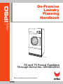
1
On-Premise
Laundry
Planning
Handbook
TM795C
TMB795C
50 and 75 Pound Tumblers
Through Serial No. 0904002963
Refer to Installation manual for full instructions.
4-08-44R3
June 2011
Table of
Contents
Tumblers – 50 and 75 .........................................................................
Introduction......................................................................................
Model Identification ..................................................................
Specifications and Dimensions ........................................................
Cabinet Dimensions...................................................................
Exhaust Outlet Locations...........................................................
Gas Connection Locations.........................................................
Electrical Connection Locations................................................
Steam Connection Locations .....................................................
Installation........................................................................................
Pre-Installation Inspection .........................................................
Tumbler Enclosure.....................................................................
Exhaust Requirements .....................................................................
Layout ........................................................................................
Make-Up Air..............................................................................
Venting ......................................................................................
Individual Venting .....................................................................
Manifold Venting.......................................................................
50 Pound Gas and Steam Models ....................................................
75 Pound Gas and Steam Models ....................................................
50 and 75 Pound Electric Models ....................................................
2
2
2
4
5
6
7
8
9
10
10
11
12
12
12
12
13
15
18
19
20
© Published by permission of the copyright owner.
All rights reserved. No part of the contents of this book may be reproduced or transmitted in any form or by any
means without the expressed written consent of the publisher.
1
© Copyright, Alliance Laundry Systems LLC – DO NOT COPY or TRANSMIT
4-08-44
Tumblers – 50 and 75
Introduction
TMB795C
TMB795C
Model Identification
Gas
50 Pound IPD50G2-IT050L
75 Pound IPD75G2-IT075L
IPD50G2-IT050N
IPD75G2-IT075N
Steam/Thermal Oil
IPD50S2-IT050S
IPD75S2-IT075S
Includes models with the following control suffixes:
3V – DX4 vended
QT – dual digital timer
3X – DX4 prep for coin
RD – reversing DMP OPL
DO – DMP OPL
RQ – reversing dual digital timer
4-08-44
IPD50S2-IT050T
IPD75S2-IT075T
Electric
IPD50E2-IT050E
IPD75E2-IT075E
SD – single drop
SX – single drop, prep for coin
© Copyright, Alliance Laundry Systems LLC – DO NOT COPY or TRANSMIT
2
Tumblers – 50 and 75
0
5
15
OL
COWN
DO
E
UR
AT LOW
ER
MP
TE
H
HIG
10
10
0
AT
HE
60
50
20
1
30
40
SH
PU
TO T
AR
ST
1
TMB803N
TMB803N
1
Serial Plate
Conversion Table
Multiply
To Obtain
Multiply
By
To Obtain
Btu
0.252
kCal
Pounds/sq. inch
0.06895
Btu
1055
Joules
Pounds/sq. inch
0.070
kg/sq. cm
Inch
25.4
Millimeters
Pounds (lbs.)
0.454
Kilograms
Bars
Inches W.C.
0.036
Pounds/sq. inch
Boiler Horsepower
33,479
Inches W.C.
0.249
kPa
Boiler Horsepower
34.5
lbs. steam/hr.
lb/inch2 (psi)
6.895
kPa
CFM
0.471
liters/second
28.32
Liters
kW
3414
Btu/hr.
ft
3
By
3
© Copyright, Alliance Laundry Systems LLC – DO NOT COPY or TRANSMIT
Btu/hr.
4-08-44
Tumblers – 50 and 75
Specifications and Dimensions
Specifications
50 Pound
75 Pound
Noise level measured during operation at
operator position of 3.3 feet (1 meter) in front
of machine and 5.2 feet (1.6 meters) from
floor.
63 dBA
69 dBA
545
(247)
615
(279)
37 x 30
(940 x 762)
37 x 36
(940 x 914)
Cylinder Capacity (dry weight):
Pounds (kg)
50
(22.7)
75
(34)
Air Outlet Diameter:
Inches (mm)
8
(203)
8
(203)
Maximum Static Back Pressure:
W.C.I. (mbar)
0.5
(1.3)
0.5
(1.3)
Net Weight (approximate):
Pounds (kg)
Cylinder Size:
Inches (mm)
750
(354)
Maximum Airflow:
C.F.M. (L/sec.)
Motor Horsepower:
Nonreversing
Reversing
Fan
Cylinder
Gas/Steam 60 Hz 920 (434)
Gas/Steam 50 Hz 750 (354)
Electric
750 (354)
1/2
3/4
1/3
1/3
1/3
1/3
Gas Models
Gas Connection
Gas Burner Rating:
Btu/hr0 (Mj/hr.)
1/2 in. NPT
1/2 in. NPT
120,000
(126.6)
165,000
(174.1)
Electric Models
Heating Element Rating:
Kilowatts (kW)
21 kW (240 V/50 Hz)
30 kW (other voltages)
30 kW
Steam Models
Steam Connection
Steam Coil Rating at 100 psig:
Boiler Horsepower (Btu/hr.)
(recommended operating pressure
80-100 psig)
4-08-44
3/4 in. NPT
3/4 in. NPT
5.1
(177,500)
6.1
(210,300)
© Copyright, Alliance Laundry Systems LLC – DO NOT COPY or TRANSMIT
4
Tumblers – 50 and 75
Cabinet Dimensions
C
E
B
D
A
F
G
TMB2210N
Models
A
*
B
**
*
**
C
D
E
F
G
50
Pound
Gas and
Electric
30.75 in. 28.75 in. 28.25 in. 33.87 in.
47 in.
76.625 in.
(781 mm) (730 mm) (717 mm) (860 mm) (1194 mm) (1946 mm)
38.625 in.
(981 mm)
33 in.
29.5 in.
(838 mm) (749 mm)
50
Pound
Steam
30.75 in. 28.75 in. 28.25 in. 33.87 in.
47 in.
80 in.
(781 mm) (730 mm) (717 mm) (860 mm) (1194 mm) (2032 mm)
38.625 in.
(981 mm)
33 in.
29.5 in.
(838 mm) (749 mm)
75
Pound
Gas and
Electric
30.75 in. 28.75 in. 28.25 in. 33.87 in.
53 in.
76.625 in.
(781 mm) (730 mm) (717 mm) (860 mm) (1346 mm) (1946 mm)
38.625 in.
(981 mm)
33 in.
35.5 in.
(838 mm) (902 mm)
75
Pound
Steam
30.75 in. 28.75 in. 28.25 in. 33.87 in.
53 in.
80 in.
(781 mm) (730 mm) (717 mm) (860 mm) (1346 mm) (2032 mm)
38.625 in.
(981 mm)
33 in.
35.5 in.
(838 mm) (902 mm)
* A, H, S and U models prior to Serial No. 0308001307 and all other models.
** A, H, N, S and U models after Serial No. 0308001307.
5
© Copyright, Alliance Laundry Systems LLC – DO NOT COPY or TRANSMIT
4-08-44
Tumblers – 50 and 75
Exhaust Outlet Locations
B
C
A
TMB811N
4-08-44
A
B
C
5.375 in.
(137 mm)
8 in.
(203 mm)
13.375 in.
(340 mm)
© Copyright, Alliance Laundry Systems LLC – DO NOT COPY or TRANSMIT
6
Tumblers – 50 and 75
Gas Connection Locations
A
B
TMB812N
Models
50 Pound
75 Pound
7
Diameter
A
B
1/2 in. NPT
15.5 in.
(394 mm)
65.75 in.
(1670 mm)
1/2 in. NPT
15.75 in.
(400 mm)
65.75 in.
(1670 mm)
© Copyright, Alliance Laundry Systems LLC – DO NOT COPY or TRANSMIT
4-08-44
Tumblers – 50 and 75
Electrical Connection Locations
A
A
B
B
TMB813N
GAS AND STEAM
ELECTRIC
TMB813N
Models
A
B
Gas and Steam
9.5 in.
(241 mm)
63.5 in.
(1613 mm)
Electric
19 in.
(483 mm)
64 in.
(1626 mm)
NOTE: These figures are approximate dimensions only.
4-08-44
© Copyright, Alliance Laundry Systems LLC – DO NOT COPY or TRANSMIT
8
Tumblers – 50 and 75
Steam Connection Locations
A
C
B
D
TMB814N
9
Diameter
A
B
C
D
3/4 in. NPT
15.25 in.
(387 mm)
72.75 in.
(1848 mm)
7.5 in.
(190 mm)
64.75 in.
(1645 mm)
© Copyright, Alliance Laundry Systems LLC – DO NOT COPY or TRANSMIT
4-08-44
Tumblers – 50 and 75
Installation
Pre-Installation Inspection
Upon delivery, visually inspect the crate, carton and
parts for any visible shipping damage. If the crate,
carton, or cover is damaged or signs of possible
damage are evident, have the carrier note the condition
on the shipping papers before the shipping receipt is
signed, or advise the carrier of the condition as soon as
it is discovered.
Remove the crate and protective cover as soon as
possible and check the items listed on the packing list.
Advise the carrier of any damaged or missing articles
as soon as possible. A written claim should be filed
with the carrier immediately if articles are damaged or
missing.
IMPORTANT: Warranty is void unless tumbler is
installed according to instructions in this manual.
Installation should comply with minimum
specifications and requirements detailed herein,
and with applicable local gas fitting regulations,
municipal building codes, water supply regulations,
electrical wiring regulations, and any other
relevant statutory regulations. Due to varied
requirements, applicable local codes should be
thoroughly understood and all pre-installation
work arranged for accordingly.
4-08-44
© Copyright, Alliance Laundry Systems LLC – DO NOT COPY or TRANSMIT
10
Tumblers – 50 and 75
Tumbler Enclosure
WARNING
To reduce the risk of severe injury, clearance of tumbler cabinet from combustible
construction must conform to the minimum clearances.
W056
1
3
4
2
5
6
7
8
TMB2131N
TMB2131N
NOTE: Shaded areas indicate adjacent structure.
1
0.5 in. (13 mm) recommended between machines for removal or installation
2
Allow 2-4 in. (51-102 mm) opening at top of machine to aid in removal or installation. A removable trim piece
may be used to conceal the opening; zero clearance allowed for trim.
3
4 in. (102 mm) maximum header thickness
4
12 in. (305 mm) minimum clearance permitted for remainder
5
Guard
6
Provision for make-up air
7
24 in. (610 mm) minimum, 36 in. (914 mm) recommended for maintenance purposes
8
0.25 in. (6 mm) recommended for removal or installation purposes, zero clearance allowed
Figure 1
11
© Copyright, Alliance Laundry Systems LLC – DO NOT COPY or TRANSMIT
4-08-44
Tumblers – 50 and 75
Exhaust Requirements
WARNING
A drying tumbler produces combustible
lint. To reduce the risk of fire, the tumbler
must be exhausted to the outdoors.
W057
To reduce the risk of fire and accumulation
of combustible gases, DO NOT exhaust
tumbler air into a window well, gas vent,
chimney or enclosed, unventilated area
such as an attic wall, ceiling, crawl space
under a building, or concealed space of a
building.
W059
Layout
Whenever possible, install tumblers along an outside
wall where duct length can be kept to a minimum, and
make-up air can be easily accessed. Elbows and long
vents tend to increase drying time. Construction must
not block the airflow at the rear of the tumbler. Doing
so would prevent adequate air supply to the tumbler’s
combustion chamber.
Make-Up Air
A tumbler is forced air exhausted and requires
provisions for make-up air to replace the air exhausted
by the tumbler.
IMPORTANT: Do not obstruct the flow of
combustion and ventilation air.
Make-up air openings should be as close to the
tumbler(s) as possible.
The required make-up air opening to the outside for
each tumbler is:
Required Make-Up Air Opening
(to the outside) for Each Tumbler
Model
Opening
50 Pound
144 in2 (928 cm2)
75 Pound
195 in2 (1258 cm2)
Make-up air openings with louvers will restrict
airflow. The opening must be increased to compensate
for area taken up by louvers.
Make-up air openings for a room containing
tumbler(s) and/or gas fired hot water heater or other
gravity vented appliances must be increased
sufficiently to prevent downdrafts in any of the vents
when all tumblers are in operation. Do not locate
gravity vented appliances between tumbler(s) and
make-up air openings. If it is necessary to duct makeup air to the tumbler(s), increase the area of the
ductwork by 25% to compensate for any restriction in
air movement.
Venting
WARNING
To reduce the risk of fire due to increased
static pressure, we do not recommend
installation of in-line secondary lint filters
or lint collectors. If secondary systems
are mandated, frequently clean the
system to assure safe operation.
W749
IMPORTANT: Installing in-line filters or lint
collectors will cause increased static pressure.
Failure to maintain the secondary lint system will
decrease tumbler efficiency and may void machine
warranty.
For maximum efficiency and minimum lint
accumulation, tumbler air must be exhausted to the
outdoors by the shortest possible route.
Proper sized exhaust ducts are essential for proper
operation. All elbows should be sweep type. Exhaust
ducts must be assembled so the interior surfaces are
smooth, so the joints do not permit the accumulation
of lint. DO NOT use plastic or thin foil flexible ducts –
rigid metal ducts are recommended. Use exhaust ducts
made of sheet metal or other noncombustible material.
DO NOT use sheet metal screws or fasteners on
exhaust pipe joints which extend into the duct and
catch lint. Use of duct tape or pop-rivets on all seams
and joints is recommended, if allowed by local code.
Verify that old ducts are thoroughly cleaned out before
installing new tumbler(s).
WARNING
Improperly sized or assembled ductwork
causes excess back pressure which
results in slow drying, lint collecting in the
duct, lint blowing back into the room, and
increased fire hazard.
W355
4-08-44
© Copyright, Alliance Laundry Systems LLC – DO NOT COPY or TRANSMIT
12
Tumblers – 50 and 75
NOTE: Exhaust ducts must be constructed of sheet
metal or other noncombustible material. Such
ducts must be equivalent in strength and corrosion
resistance to ducts made of galvanized sheet steel
not less than 0.0195 inches (0.495 mm) thick. Local
codes may require additional thickness.
Where the exhaust duct pierces a combustible wall or
ceiling the opening must be sized per local codes. The
space around the duct may be sealed with
noncombustible material. Refer to Figure 2.
IMPORTANT: For best performance provide an
individual exhaust duct for each tumbler. Do not
install a hot water heater in a room containing
tumblers. It is better to have the water heater in a
separate room with a separate air inlet.
Individual Venting
For maximum efficiency and performance, it is
preferred to exhaust tumbler(s) individually to the
outdoors.
IMPORTANT: At no point may the cross sectional
area of installed venting be less than the cross
sectional area of the exhaust outlet of the tumbler.
The exhaust duct must be designed so the static back
pressure measured 12 inches (305 mm) from the
exhaust outlet does not exceed the maximum
allowable pressure specified on the installation sticker
on the rear of the tumbler.
Duct
Diameter
6 in. (152 mm)
8 in. (203 mm)
10 in. (254 mm)
12 in. (305 mm)
14 in. (356 mm)
16 in. (406 mm)
18 in. (457 mm)
Equivalent Length of Rigid
Straight Duct
One 90° elbow = 7 ft. (2.1 m)
One 90° elbow = 9.3 ft. (2.83 m)
One 90° elbow = 11.6 ft. (3.5 m)
One 90° elbow = 14 ft. (4.3 m)
One 90° elbow = 16 ft. (4.9 m)
One 90° elbow = 18.7 ft. (5.7 m)
One 90° elbow = 21 ft. (6.4 m)
Equivalent Length (feet) = 1.17 x Duct Diameter (inches)
Table 1
Example: A 12 inch (305 mm) diameter duct’s
equivalent length of 14 feet (4.3 m) of duct and two
90° elbows is:
Equivalent Length = 14 feet + (2) 90° elbows
= 14 feet + 14 feet + 14 feet
= 42 feet (12.8 meters)
With the tumbler in operation, airflow at any point
in the duct should be at least 1200 feet per minute
(366 meters per minute) to ensure that lint remains
airborne. If 1200 feet per minute cannot be
maintained, schedule monthly inspections and
cleaning of the ductwork.
NOTE: Static back pressure must be measured
with the tumbler running.
The maximum allowable length venting of the same
diameter as the exhaust thimble is 14 feet (4.3 m) and
two 90° elbows or equivalent. If the equivalent length
of a duct required for an installation exceeds the
maximum allowable equivalent length, the diameter of
a round duct must be increased by 10% for each
additional 20 feet (6.1 m). Cross section area of a
rectangular duct must be increased by 20% for each
additional 20 feet (6.1 m). Refer to Table 1 to
determine equivalent venting.
NOTE: The maximum length of a flexible metal
duct must not exceed 7.87 ft. (2.4 m) as required to
meet UL2158, claus 7.3.2A.
13
© Copyright, Alliance Laundry Systems LLC – DO NOT COPY or TRANSMIT
4-08-44
Tumblers – 50 and 75
3
4
2
1
5
TMB2103N
TMB2103N
1
2
3
4
5
Removable strip of panel in framing wall to permit removal of tumbler from framing wall
Partition or bulkhead
Minimum distance between exhaust opening and roof, ground or other obstruction: 36 in. (914 mm)
2 in. (51 mm) minimum clearance on both sides of duct
Exhaust airflow – maximum length of duct: 14 ft. (4.3 m)
Figure 2
NOTE: Do not install wire mesh or screen in
exhaust duct opening to avoid lint build-up or
impacting proper discharge of air from tumblers.
NOTE: Where exhaust duct pierces a combustible
wall or ceiling, the opening must be sized per local
codes.
4-08-44
NOTE: Inside of duct must be smooth. Do not use
sheet metal screws to join sections.
Consult your local building code for regulations which
may also apply.
© Copyright, Alliance Laundry Systems LLC – DO NOT COPY or TRANSMIT
14
Tumblers – 50 and 75
Manifold Venting
While it is preferable to exhaust tumblers individually
to the outdoors, a main collector duct may be used if it
is sized according to Figure 4 and Figure 5. This
illustration indicates minimum diameters, which
should be increased if the collector length exceeds 14
feet (4.3 meters) and two 90° elbows. The diameter of
a round duct must be increased by 10% for each
additional 20 feet (6.1 meters). Cross sectional area of
a rectangular or square duct must be increased 20% for
each additional 20 feet (6.1 meters). Refer to Table 2
and Table 3 to determine equivalent ducting sizing.
The collector duct may be rectangular or square in
cross section, as long as the area is not reduced.
Provisions MUST be made for lint removal and
cleaning of the collector duct.
The vent collector system must be designed so the
static back pressure measured 12 inches (305 mm)
from the exhaust outlet does not exceed the maximum
allowable pressure specified on the installation sticker
on the rear of tumbler. Static back pressure must be
measured with all tumblers vented into the collector
operating.
15
NOTE: Never connect a tumbler duct at a 90°
angle to the collector duct. Refer to Figure 3. Doing
so will cause excessive back pressure, resulting in
poor performance. Never connect two tumbler
exhaust ducts directly across from each other at the
point of entry to the collector duct.
With the tumbler in operation, airflow at any point in
the duct should be at least 1200 feet per minute (366
meters per minute) to ensure that lint remains airborne.
If 1200 feet per minute cannot be maintained, schedule
monthly inspections and cleaning of the ductwork.
T438I
Figure 3
© Copyright, Alliance Laundry Systems LLC – DO NOT COPY or TRANSMIT
4-08-44
Tumblers – 50 and 75
1
2
L
K
3
J
I
H
G
F
E
D
C
B
A
ONE MANIFOLD ASSEMBLY
TMB2019N
1
NOTE: Where the exhaust duct pierces a
combustible wall or ceiling, the opening
MUST be sized per local codes.
2
Outlet duct diameter
3
45° typical
Figure 4
Duct Station
8 in. (203 mm) Duct
A
8 in. (203 mm)
B
12 in. (305 mm)
C
15 in. (381 mm)
D
17 in. (432 mm)
E
19 in. (483 mm)
F
21 in. (533 mm)
G
23 in. (584 mm)
H
25 in. (635 mm)
I
26 in. (660 mm)
J
27 in. (686 mm)
K
29 in. (737 mm)
L
30 in. (762 mm)
Table 2
4-08-44
© Copyright, Alliance Laundry Systems LLC – DO NOT COPY or TRANSMIT
16
Tumblers – 50 and 75
1
2
I
J
K
L
L
K
J
I
CONTINUE
TO A
CONTINUE
TO A
TWO MANIFOLD ASSEMBLIES
3
TMB2018N
1
NOTE: Where the exhaust duct pierces a
combustible wall or ceiling, the opening
MUST be sized per local codes.
2
Outlet duct diameter
3
45° typical
Figure 5
Duct Station
8 in. (203 mm) Duct
A
13 in. (330 mm)
B
17 in. (432 mm)
C
18 in. (457 mm)
D
24 in. (610 mm)
E
27 in. (686 mm)
F
30 in. (762 mm)
G
33 in. (838 mm)
H
34 in. (864 mm)
I
37 in. (940 mm)
J
39 in. (991 mm)
K
40 in. (1016 mm)
L
42 in. (1067 mm)
Table 3
17
© Copyright, Alliance Laundry Systems LLC – DO NOT COPY or TRANSMIT
4-08-44
Tumblers – 50 and 75
50 Pound Gas and Steam Models
Refer to Table 4.
NOTE: Wire sizes were obtained from the
Canadian Electrical Code for 75 C. wire and are
intended for use as a guideline only. Electrical
connections should be made by a qualified
electrical contractor in accordance with all
applicable local and national requirements.
NOTE: Electrical specifications below are subject
to change without notice. Always refer to product
serial plate for most current specifications of
product being installed.
NOTE: Use copper conductors only.
NOTE: Connect to individual branch circuit.
NOTE: 3 Phase Only – Each tumbler must be
connected to its own individual branch circuit
breaker, not fuses, to avoid the possibility of “single
phasing” and causing premature failure of the
motor(s).
7
Serial Plate Rating
Terminal Block
Connections
Required
Serial Plate Amps
Recommended Circuit
Nonreversing Reversing Breaker Rating
Wire Size
AWG (mm2)
120V/60Hz/1ph
L1, Neutral and ground
9.3
N/A
15A – 1 pole
14 (2.08)
200-208V/60Hz/1ph
L1, Neutral and ground
5.1
N/A
10A – 1 pole
14 (2.08)
200-208-240V/60Hz/1ph
L1, L2 and ground
5.1
N/A
10A – 2 pole
14 (2.08)
230-240V/50Hz/1ph
L1, Neutral and ground
6.3
6.9
15A – 1 pole
14 (2.08)
200-208V/60Hz/3ph
L1, L2, L3 and ground
2.8
4.0
10A – 3 pole
14 (2.08)
200V/50Hz/3ph
L1, L2, L3 and ground
3.3
4.2
10A – 3 pole
14 (2.08)
240V/60Hz/3ph
L1, L2, L3 and ground
2.8
4.0
10A – 3 pole
14 (2.08)
230-240V/50Hz/3ph
L1, L2, L3 and ground
3.1
4.3
10A – 3 pole
14 (2.08)
380V/50 or 60Hz/3ph
L1, L2, L3 and ground
1.6
2.0
10A – 3 pole
14 (2.08)
400-415V/50Hz/3ph
L1, L2, L3 and ground
1.6
2.0
10A – 3 pole
14 (2.08)
440V/60Hz/3ph
L1, L2, L3 and ground
1.4
1.9
10A – 3 pole
14 (2.08)
460-480V/60Hz/3ph
L1, L2, L3 and ground
1.4
1.9
10A – 3 pole
14 (2.08)
N/A = Not Applicable
Table 4
4-08-44
© Copyright, Alliance Laundry Systems LLC – DO NOT COPY or TRANSMIT
18
Tumblers – 50 and 75
75 Pound Gas and Steam Models
NOTE: Use copper conductors only.
Refer to Table 5.
NOTE: Connect to individual branch circuit.
NOTE: Wire size and breaker ratings were
obtained from the Canadian Electrical Code for
75 C. wire and are intended for use as a guideline
only. Electrical connections should be made by a
qualified electrical contractor in accordance with
all applicable local and national requirements.
NOTE: 3 Phase Only – Each tumbler must be
connected to its own individual branch circuit
breaker, not fuses, to avoid the possibility of “single
phasing” and causing premature failure of the
motor(s).
NOTE: Electrical specifications below are subject
to change without notice. Always refer to product
serial plate for most current specifications of
product being installed.
Terminal Block
Connections
Required
Serial Plate Rating
Serial Plate Amps
Nonreversing Reversing
Recommended Circuit
Breaker
Rating
Wire Size
AWG (mm2)
120V/60Hz/1ph
L1, Neutral and ground
13.8
N/A
20A – 1 pole
12 (3.31)
200-208V/60Hz/1ph
L1, Neutral and ground
7.6
N/A
15A – 1 pole
14 (2.08)
200-208-240V/60Hz/1ph
L1, L2 and ground
7.6
N/A
15A – 2 pole
14 (2.08)
230-240V/50Hz/1ph
L1, Neutral and ground
6.7
7.0
15A – 1 pole
14 (2.08)
200-208V/60Hz/3ph
L1, L2, L3 and ground
3.8
4.3
10A – 3 pole
14 (2.08)
200V/50Hz/3ph
L1, L2, L3 and ground
3.5
4.5
10A – 3 pole
14 (2.08)
240V/60Hz/3ph
L1, L2, L3 and ground
3.8
4.3
10A – 3 pole
14 (2.08)
230-240V/50Hz/3ph
L1, L2, L3 and ground
3.5
4.9
10A – 3 pole
14 (2.08)
380V/50 or 60Hz/3ph
L1, L2, L3 and ground
1.8
2.1
10A – 3 pole
14 (2.08)
400-415V/50Hz/3ph
L1, L2, L3 and ground
1.8
2.1
10A – 3 pole
14 (2.08)
440V/60Hz/3ph
L1, L2, L3 and ground
1.9
2.1
10A – 3 pole
14 (2.08)
460-480V/60Hz/3ph
L1, L2, L3 and ground
1.9
2.1
10A – 3 pole
14 (2.08)
N/A = Not Applicable
Table 5
19
© Copyright, Alliance Laundry Systems LLC – DO NOT COPY or TRANSMIT
4-08-44
Tumblers – 50 and 75
50 and 75 Pound Electric Models
NOTE: Use copper conductors only.
Refer to Table 6.
NOTE: Connect to individual branch circuit.
NOTE: Wire size and breaker ratings were
obtained from the Canadian Electrical Code for
75 C. wire and are intended for use as a guideline
only. Electrical connections should be made by a
qualified electrical contractor in accordance with
all applicable local and national requirements.
NOTE: 3 Phase Only – Each tumbler must be
connected to its own individual branch circuit
breaker, not fuses, to avoid the possibility of “single
phasing” and causing premature failure of the
motor(s).
NOTE: Electrical specifications below are subject
to change without notice. Always refer to product
serial plate for most current specifications of
product being installed.
Serial Plate Amps
Recommended Circuit
Terminal Block
Connections
Required
Nonreversing
Reversing
Breaker
Rating
Wire Size
AWG (mm2)
240V/50Hz/1ph
(50 Pound only)
L1, Neutral and Ground
93
95
125A – 1 pole
1 (42.4)
200-208V/60Hz/3ph
L1, L2, L3 and ground
89
88
125A – 3 pole
1 (42.4)
200V/50Hz/3ph
L1, L2, L3 and ground
84
85
125A – 3 pole
1 (42.4)
230V/50Hz/3ph
L1, L2, L3 and ground
73
75
100A – 3 pole
3 (26.7)
240V/50Hz/3ph
L1, L2, L3 and ground
79
78
100A – 3 pole
3 (26.7)
240V/60Hz/3ph
L1, L2, L3 and ground
79
78
100A – 3 pole
3 (26.7)
380V/50 or 60Hz/3ph
L1, L2, L3 and ground
47
48
60A – 3 pole
6 (13.3)
400-415V/50Hz/3ph
L1, L2, L3 and ground
43
44
60A – 3 pole
6 (13.3)
440V/60Hz/3ph
L1, L2, L3 and ground
41
41
51A – 3 pole
6 (13.3)
480V/60Hz/3ph
L1, L2, L3 and ground
38
38
50A – 3 pole
6 (13.3)
Serial Plate Rating
Table 6
4-08-44
© Copyright, Alliance Laundry Systems LLC – DO NOT COPY or TRANSMIT
20