1
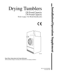
50 Pound Capacity
75 Pound Capacity
Refer to page 3 for Model Identification
Keep These Instructions for Future Reference.
(If this machine changes ownership, this manual must accompany machine.)
www.comlaundry.com
Part No. 70278501R5EN
December 2007
Installation/Operation Supplement
Drying Tumblers
Installation/Operation Supplement
Installation must conform with local codes.
WARNING
WARNING
FOR YOUR SAFETY, the information in
this manual must be followed to minimize
the risk of fire or explosion or to prevent
property damage, personal injury or
death.
W033
• Do not store or use gasoline or other
flammable vapors and liquids in the
vicinity of this or any other appliance.
• WHAT TO DO IF YOU SMELL GAS:
– Do not try to light any appliance.
– Do not touch any electrical switch; do
not use any phone in your building.
– Clear the room, building or area of all
occupants.
– Immediately call your gas supplier
from a neighbor’s phone. Follow the
gas supplier’s instructions.
– If you cannot reach your gas supplier,
call the fire department.
• Installation and service must be
performed by a qualified installer,
service agency or the gas supplier.
W052
FOR YOUR SAFETY
Do not store or use gasoline or other
flammable vapors and liquids in the
vicinity of this or any other appliance.
W053
IMPORTANT: Information must be obtained from
a local gas supplier on instructions to be followed if
the user smells gas. These instructions must be
posted in a prominent location. Step-by-step
instructions of the above safety information must
be posted in a prominent location near the tumbler
for customer use.
70278501 (EN)
To reduce the risk of fire, electric shock,
serious injury or death to persons when
using the tumbler unit, follow these basic
precautions:
• Read all instructions before using
tumbler.
• DO NOT tamper with controls.
• DO NOT bypass any safety devices.
• Always follow the fabric care
instructions supplied by the garment
manufacturer.
• Remove laundry immediately after the
tumbler stops.
• DO NOT reach into tumbler if cylinder is
revolving.
To avoid creating any flammable vapors
which may explode, ignite or cause
corrosive damage, DO NOT dry the
following materials:
• Articles that have been cleaned in,
soaked in, washed in or spotted with
gasoline, dry-cleaning solvents or other
flammable/explosive substances.
• Plastics or articles containing foam
rubber or similarly textured rubberlike
materials.
• Articles that have traces of flammable
substances like cooking oil, machine
oil, flammable chemicals or thinner.
• Articles containing wax or cleaning
chemicals.
• Fiberglass curtains or draperies (unless
the label says it can be done).
© Published by permission of the copyright owner – DO NOT COPY or TRANSMIT
W440R1
1
Installation/Operation Supplement
Table of
Contents
Introduction.........................................................................................
Model Identification .............................................................................
Wiring Diagram ....................................................................................
Serial Plate Location.............................................................................
3
3
3
4
Safety Information..............................................................................
Important Safety Instructions ...............................................................
5
5
Installation...........................................................................................
Specifications and Dimensions.............................................................
Cabinet Dimensions .........................................................................
Horizontal Exhaust Outlet Locations...............................................
Gas Connection Locations ...............................................................
Electrical Connection Locations ......................................................
Steam Connection Locations ...........................................................
Position and Level the Tumbler............................................................
Fire Suppression System.......................................................................
Water Requirements.........................................................................
Water Connections...........................................................................
Electrical Requirements ...................................................................
Auxiliary Alarm ...............................................................................
Gas Requirements.................................................................................
Natural Gas and Liquefied Petroleum..............................................
European Gas ...................................................................................
Exhaust Requirements ..........................................................................
Make-Up Air ....................................................................................
Venting.............................................................................................
Electrical Requirements........................................................................
Grounding Instructions ....................................................................
Steam Requirements .............................................................................
Thermal Oil Prep ..................................................................................
7
7
8
9
10
11
12
13
14
14
14
14
14
15
15
16
18
18
18
19
19
20
20
Operation.............................................................................................
Emergency Stop Button on CE Models................................................
Operating Instructions ..........................................................................
Step 1: Clean Lint Screen/Compartment .........................................
Step 2: Load Laundry.......................................................................
Step 3: Determine Control Type and Temperature Setting .............
Step 4: Remove Laundry .................................................................
Control Instructions ..............................................................................
Electromechanical Coin Control......................................................
Manual Timer Control .....................................................................
Dual Digital Timer Control..............................................................
Single Drop Control .........................................................................
DMP OPL Control ...........................................................................
DMP Coin Control ...........................................................................
Ignition Control Operation ...................................................................
22
22
22
22
22
22
22
23
23
24
25
26
27
28
29
Disposal of Unit ................................................................................... 30
© Published by permission of the copyright owner.
All rights reserved. No part of the contents of this book may be reproduced or transmitted in any form or by any
means without the expressed written consent of the publisher.
2
© Published by permission of the copyright owner – DO NOT COPY or TRANSMIT
70278501 (EN)
Installation/Operation Supplement
Introduction
Model Identification
Information in this manual is applicable to these models:
Gas
Steam/Thermal Oil
Electric
50 Pound
CHD50G2-CU050L
CHD50G2-CU050N
DR50G2-BU050L
DR50G2-BU050N
BU050T
CHD50S2-CU050S
CU050T
DR50S2-BU050S
CHD50E2-CU050E
DR50E2-BU050E
75 Pound
CHD75G2-CU075L
CHD75G2-CU075N
DR75G2-BU075L
DR75G2-BU075N
BU075T
CHD75S2-CU075S
CU075T
DR75S2-BU075S
CHD75E2-CU075E
DR75E2-BU075E
Includes models with the following control suffixes:
3O – DX4 OPL
3V – DX4 vended
3X – DX4 prep for coin
CD – rotary coin drop
CX – prep for coin
DO – DMP OPL
DV – DMP vended
DX – DMP prep for coin
MT– manual timer
QT – dual digital timer
R3 – reversing DX4 OPL
RD – reversing DMP OPL
RQ – reversing dual digital timer
RT – reversing manual timer
SD – single drop
SX – single drop, prep for coin
Wiring Diagram
The wiring diagram is located in the junction or
contactor box.
70278501 (EN)
© Published by permission of the copyright owner – DO NOT COPY or TRANSMIT
3
Installation/Operation Supplement
Serial Plate Location
0
5
15
T
HEA
20
30
OL
COWN
DO
RE
ATU LOW
PER
TEM
H
HIG
10
10
0
60
50
1
40
H
PUS
TORT
STA
1
TMB803N
TMB803N
1
4
Serial Plate
© Published by permission of the copyright owner – DO NOT COPY or TRANSMIT
70278501 (EN)
Installation/Operation Supplement
Safety Information
Save These Instructions
Important Safety Instructions
13. Keep area around the exhaust opening and
adjacent surrounding area free from the
accumulation of lint, dust and dirt.
WARNING
Hazardous Voltage. Can cause shock, burn
or cause death. Allow machine power to
remain off for two minutes prior to working
in and around AC inverter drive.
W359
1. Read all instructions before using the tumbler.
2. Refer to the GROUNDING INSTRUCTIONS
for the proper grounding of the tumbler.
3. Do not dry articles that have been previously
cleaned in, washed in, soaked in, or spotted with
gasoline, dry-cleaning solvents, or other
flammable or explosive substances, as they give
off vapors that could ignite or explode.
14. The interior of the tumbler and the exhaust duct
should be cleaned periodically by qualified
service personnel.
15. If not installed, operated and maintained in
accordance with the manufacturer’s instructions
or if there is damage to or mishandling of this
product’s components, use of this product could
expose you to substances in the fuel or from fuel
combustion which can cause death or serious
illness and which are known to the State of
California to cause cancer, birth defects or other
reproductive harm.
4. Do not allow children to play on or in the
tumbler. This appliance is not intended for use by
young children or infirm persons without
supervision. Young children should be
supervised to ensure that they do not play with
the appliance.
16. Tumbler will not operate with the loading door
open. DO NOT bypass the door safety switch to
permit the tumbler to operate with the door open.
The tumbler will stop tumbling when the door is
opened. Do not use the tumbler if it does not stop
tumbling when the door is opened or starts
tumbling without pressing or turning the START
mechanism. Remove the tumbler from use and
call for service.
5. Before the tumbler is removed from service or
discarded, remove the door to the drying
compartment and the door to the lint
compartment.
17. Tumbler will not operate with lint panel open.
DO NOT bypass lint panel safety switch to
permit the tumbler to operate with the lint panel
open.
6. Do not reach into the tumbler if the cylinder is
revolving.
18. Do not put articles soiled with vegetable or cooking
oil in the tumbler, as these oils may not be
removed during washing. Due to the remaining
oil, the fabric may catch on fire by itself.
7. Do not install or store the tumbler where it will
be exposed to water and/or weather.
8. Do not tamper with the controls.
9. Do not repair or replace any part of the tumbler,
or attempt any servicing unless specifically
recommended in the user-maintenance
instructions or in published user-repair
instructions that you understand and have the
skills to carry out.
10. Do not use fabric softeners or products to
eliminate static unless recommended by the
manufacturer of the fabric softener or product.
11. To reduce the risk of fire, DO NOT DRY plastics
or articles containing foam rubber or similarly
textured rubberlike materials.
19. To reduce the risk of fire, DO NOT put clothes
which have traces of any flammable substances
such as machine oil, flammable chemicals,
thinner, etc. or anything containing wax or
chemicals such as in mops and cleaning cloths, or
anything dry-cleaned at home with dry-cleaning
solvent in the tumbler.
20. Use the tumbler only for its intended purpose,
drying fabrics.
21. ALWAYS disconnect and lockout the electrical
power to the tumbler before servicing.
Disconnect power by shutting off appropriate
breaker or fuse.
12. Always clean the lint filter daily.
70278501 (EN)
© Published by permission of the copyright owner – DO NOT COPY or TRANSMIT
5
Installation/Operation Supplement
22. Install this tumbler according to the
INSTALLATION INSTRUCTIONS. All
connections for electrical power, grounding, and
gas supply must comply with local codes and be
made by licensed personnel when required.
23. Remove laundry immediately after tumbler stops.
24. Always read and follow manufacturer’s
instructions on packages of laundry and cleaning
aids. Heed all warnings or precautions. To reduce
the risk of poisoning or chemical burns, keep
them out of reach of children at all times
(preferably in a locked cabinet).
25. Do not tumble fiberglass curtains and draperies
unless the label says it can be done. If they are
dried, wipe out the cylinder with a damp cloth to
remove particles of fiberglass.
26. Always follow the fabric care instructions
supplied by the garment manufacturer.
27. Never operate the tumbler with any guards and/or
panels removed.
6
28. DO NOT operate the tumbler if it is smoking,
grinding, has missing or broken parts.
29. DO NOT bypass any safety devices.
30. Solvent vapors from dry-cleaning machines
create acids when drawn through the heater of the
drying unit. These acids are corrosive to the
tumbler as well as to the laundry load being
dried. Be sure make-up air is free of solvent
vapors.
31. Failure to install, maintain, and/or operate this
machine according to the manufacturer’s
instructions may result in conditions which can
produce bodily injury and/or property damage.
WARNING
To reduce the risk of serious injury, install
lockable door(s) to prevent public access
to rear of tumblers.
© Published by permission of the copyright owner – DO NOT COPY or TRANSMIT
W055
70278501 (EN)
Installation/Operation Supplement
Installation
Specifications and Dimensions
Specifications
50 Pound
75 Pound
Noise level measured during operation at
operator position of 1 meter (3.3 feet) in front
of machine and 1.6 meters (5.2 feet) from
floor.
63 dBA
69 dBA
247
(545)
279
(615)
940 x 762
(37 x 30)
940 x 914
(37 x 36)
Cylinder Capacity (dry weight):
kg (lbs.)
22.7
(50)
34
(75)
Air Outlet Diameter:
mm (in.)
203
(8)
203
(8)
Maximum Static Back Pressure:
mbar (W.C.I.)
1.3
(0.5)
1.3
(0.5)
Net Weight (approximate):
kg (lbs.)
Cylinder Size:
mm (in.)
354
(750)
Maximum Airflow:
L/sec. (C.F.M.)
Motor Horsepower:
Nonreversing
Reversing
Fan
Cylinder
Gas/Steam 50 Hz 354 (750)
Gas/Steam 60 Hz 434 (920)
Electric
354 (750)
1/2
3/4
1/3
1/3
1/3
1/3
1/2 in. NPT
1/2 in. NPT
126.6
(120,000)
174.1
(165,000)
Gas Models
Gas Connection
Gas Burner Rating:
Mj/hr (Btu/hr)
Electric Models
Heating Elements Rating:
Kilowatts (kW)
21 kW (240 V/50 Hertz)
30 kW (other voltages)
30 kW
Steam Models
Steam Connection
Steam Coil Rating:
Btu/hr (Boiler Horsepower)
70278501 (EN)
3/4 in. NPT
3/4 in. NPT
5.1
(177,500)
6.1
(210,300)
© Published by permission of the copyright owner – DO NOT COPY or TRANSMIT
7
Installation/Operation Supplement
Cabinet Dimensions
C
E
B
D
A
F
G
TMB2213N
TMB2213N
8
Models
A
B
C
D
E
F
G
050
Gas and
Electric
781 mm
(30.75 in.)
717 mm
(28.25 in.)
1194 mm
(47 in.)
1946 mm
(76.625 in.)
981 mm
(38.625 in.)
838 mm
(33 in.)
749 mm
(29.5 in.)
050
Steam
781 mm
(30.75 in.)
717 mm
(28.25 in.)
1194 mm
(47 in.)
2032 mm
(80 in.)
981 mm
(38.625 in.)
838 mm
(33 in.)
749 mm
(29.5 in.)
075
Gas and
Electric
781 mm
(30.75 in.)
717 mm
(28.25 in.)
1346 mm
(53 in.)
1946 mm
(76.625 in.)
981 mm
(38.625 in.)
838 mm
(33 in.)
902 mm
(35.5 in.)
075
Steam
781 mm
(30.75 in.)
717 mm
(28.25 in.)
1346 mm
(53 in.)
2032 mm
(80 in.)
981 mm
(38.625 in.)
838 mm
(33 in.)
902 mm
(35.5 in.)
© Published by permission of the copyright owner – DO NOT COPY or TRANSMIT
70278501 (EN)
Installation/Operation Supplement
Horizontal Exhaust Outlet Locations
B
C
A
TMB811N
TMB811N
Models
A
B
C
050/075
137 mm
(5.375 in.)
203 mm
(8 in.)
340 mm
(13.375 in.)
70278501 (EN)
© Published by permission of the copyright owner – DO NOT COPY or TRANSMIT
9
Installation/Operation Supplement
Gas Connection Locations
A
B
TMB812N
TMB812N
10
Models
Diameter
A
B
050
1/2 in. NPT
394 mm
(15.5 in.)
1670 mm
(65.75 in.)
075
1/2 in. NPT
400 mm
(15.75 in.)
1670 mm
(65.75 in.)
© Published by permission of the copyright owner – DO NOT COPY or TRANSMIT
70278501 (EN)
Installation/Operation Supplement
Electrical Connection Locations
A
A
B
B
TMB813N
GAS AND STEAM
ELECTRIC
TMB813N
Models
A
B
Gas and Steam
241 mm
(9.5 in.)
1613 mm
(63.5 in.)
Electric
483 mm
(19 in.)
1626 mm
(64 in.)
NOTE: These figures are approximate dimensions only.
70278501 (EN)
© Published by permission of the copyright owner – DO NOT COPY or TRANSMIT
11
Installation/Operation Supplement
Steam Connection Locations
A
C
B
D
TMB814N
TMB814N
12
Models
Diameter
A
B
C
D
050/075
3/4 in. NPT
387 mm
(15.25 in.)
1848 mm
(72.75 in.)
190 mm
(7.5 in.)
1645 mm
(64.75 in.)
© Published by permission of the copyright owner – DO NOT COPY or TRANSMIT
70278501 (EN)
Installation/Operation Supplement
Position and Level the Tumbler
WARNING
To reduce the risk of severe injury, clearance of tumbler cabinet from combustible
construction must conform to the minimum clearances.
W056
1
3
4
2
5
6
7
TMB2138N
8
TMB2138N
NOTE: Shaded areas indicate adjacent structure.
1
13 mm (0.5 in.) recommended between machines for removal or installation
2
Allow 51-102 mm (2-4 in.) opening at top of machine to aid in removal or installation. A removable trim piece may
be used to conceal the opening; zero clearance allowed for trim.
3
102 mm (4 in.) maximum header thickness
4
305 mm (12 in.) minimum clearance permitted for remainder
5
Guard
6
Provision for make-up air
7
610 mm (24 in.) minimum, 914 mm (36 in.) recommended for maintenance purposes
8
6 mm (0.25 in.) recommended for removal or installation purposes, zero clearance allowed
Figure 1
NOTE: This manual is only a supplement. Refer to
installation/operation manual for full instructions.
70278501 (EN)
© Published by permission of the copyright owner – DO NOT COPY or TRANSMIT
13
Installation/Operation Supplement
Fire Suppression System
Water Requirements
IMPORTANT: Water must be supplied to the fire
suppression system, or the fire suppression system
will not operate as intended.
Connection point to the electric water solenoid valve is
a 19 mm (3/4 inch) hose. The fire suppression system
equipped tumbler must be supplied with a minimum
water pipe size of 12.7 mm (1/2 inch)and be provided
with a minimum of 138 kPa (20 psi) and a maximum
of 827 kPa (120 psi) of pressure at all times. Flowrate
must be no less than, but approximately 57 liter
(15 gallons) per minute.
NOTE: Water pressure under 138 kPa (20 psi) will
cause low flow and water leakage at water solenoid
valve.
IMPORTANT: Temperature of the water supply
must be kept between 4.4° and 48.9°C (40° and
120°F). If water in the supply line or water solenoid
valve freezes, the fire suppression system will not
operate.
IMPORTANT: If temperature sensors inside the
tumbler register a temperature below 4.4°C (40°F),
the fire suppression system control will lock out.
This feature protects against operation of the
tumbler with a possible frozen water supply. Only
when the temperature sensors register a
temperature above 4.4°C (40°F) will the machine
reset for operation.
IMPORTANT: Flexible supply line/coupling must
be used. Solenoid valve failure due to hard
plumbing connections will void the warranty. It is
recommended that a filter or strainer be installed
in the water supply line.
Water Connections
1
2
5
4
IMPORTANT: Thread hose couplings onto valve
connections finger tight, then turn 1/4 turn with
pliers. Do not cross thread or overtighten
couplings.
IMPORTANT: Replace all hoses every five years.
NOTE: Longer inlet hoses are available (as
optional equipment at extra cost) if the hoses
supplied with the tumbler are not long enough for
installation. Order hoses as follows:
Part No. 20617 Inlet hose 2.44 m (8 feet)
Part No. 20618 Inlet hose 3.05 m (10 feet)
Electrical Requirements
WARNING
Electrical power must be provided to
tumbler at all times. The fire suppression
system will be inoperative if the main
electrical power supply is disconnected.
W690
No independent external power source or supply
connection is necessary. Power to operate the 24 Volt
fire suppression system is from the rear junction/
contactor box.
Auxiliary Alarm
During tumbler installation, you have the option to
connect a separate alarm system to this auxiliary
output. Use of the auxiliary output is not required for
the fire suppression system to operate, but may be used
for additional protection.
NOTE: The auxiliary output is activated during
fire suppression system maintenance test sequence.
Consider this fact prior to your system test every
three months. (Example: If the external system uses
the auxiliary output to call the fire department,
inform the fire department before and after the fire
suppression system maintenance test.)
3
2
TMB2008N
1
2
3
4
5
Lock
Hose Couplings
Y Valve
Inlet Hoses
Opening for Auxiliary Alarm Cable
Figure 2
14
© Published by permission of the copyright owner – DO NOT COPY or TRANSMIT
70278501 (EN)
Installation/Operation Supplement
Gas Requirements
IMPORTANT: The tumbler and its manually
operated appliance gas valve must be disconnected
from the gas supply piping system during any
pressure testing of that system at test pressures in
excess of 3.45 kPa, 34.5 mbar (0.5 psi).
Natural Gas and Liquefied Petroleum
WARNING
To reduce the risk of fire or explosion, DO
NOT CONNECT THE GAS LINE TO THE
TUMBLER IF THE GAS SERVICE IS NOT
THE SAME AS THAT SPECIFIED ON THE
TUMBLER SERIAL PLATE! It will first be
necessary to convert the gas burner
orifice and gas valve. Appropriate
conversion kits are available.
W060
IMPORTANT: Any product revisions or
conversions must be made by the Manufacturer’s
Authorized Dealers, Distributors, or local service
personnel.
IMPORTANT: The installation must comply with
local codes.
WARNING
To reduce the risk of fire or explosion, if
the tumbler is to be connected to
Liquefied Petroleum (L.P.) gas, a vent to
the outdoors must be provided in the room
where the tumbler is installed.
W062
NOTE: This manual is only a supplement. Refer to
installation/operation manual for full instructions.
IMPORTANT: The tumbler must be isolated from
the gas supply piping system by closing its
individual manual shut-off valve during any
pressure testing of the gas supply piping system at
test pressure equal to or less than 3.45 kPa,
34.5 mbar (0.5 psi).
70278501 (EN)
© Published by permission of the copyright owner – DO NOT COPY or TRANSMIT
15
Installation/Operation Supplement
European Gas
Models are built in two different configurations:
WARNING
To reduce the risk of electric shock, fire,
explosion, serious injury or death:
• Disconnect electric power to the
tumbler before servicing.
• Close gas shut-off valve to gas tumbler
before servicing.
• Close steam valve to steam tumbler
before servicing.
• Never start the tumbler with any guards/
panels removed.
• Whenever ground wires are removed
during servicing, these ground wires
must be reconnected to ensure that the
tumbler is properly grounded.
●
Natural Gas – regulated/governor
●
Liquefied Petroleum (L.P.) Gas – not regulated/
no governor
Machines configured for Natural Gas (regulator/
governor) may be converted to L.P. Gas (not regulated/
no governor) with block-open kit, Part No. M400763.
Serial plates are configured for GB/IE/PT/ES/IT/GR/
LU/CH.
W002
General Information
This information is to be used when installing gas
tumblers in countries, and/or on gases, different than
the machine’s factory configuration. Tumblers are
supplied from the factory for operation on Natural Gas
or L.P. Gas in the countries of GB/IE/PT/ES/IT/GR/
LU/CH. To install machines in any other country, or
on any other gas, requires some level of modification.
16
© Published by permission of the copyright owner – DO NOT COPY or TRANSMIT
70278501 (EN)
Installation/Operation Supplement
Gases and Configurations
Country
Code
DK/NO/
SE/FI/CZ/
EE/LV/LT/
SI/SK
DE**
NL
BE/FR*
GB/IE/PT/
ES/IT/GR/
LU/CH
AT**
CY/IS/MT
HU
PL
Burner
Orifice
Pressure,
mbar
Capacity/
Model
Diameter,
mm
Quantity
Burner
Orifice
Part No.
8.9
050
075
3.7
3.6
2
3
M401000
M401014
30
No Governor
050
075
2.1
2.0
2
3
M401003
M400999
E
20
8.9
050
075
3.7
3.6
2
3
M401000
M401014
LL
25
12.6
050
075
3.7
3.6
2
3
M401000
M401014
B/P
30
No Governor
050
075
2.1
2.0
2
3
M401003
M400999
B/P
50
28.5
050
075
2.1
2.0
2
3
M401003
M400999
Natural Gas
L
25
12.6
050
075
3.7
3.6
2
3
M401000
M401014
L.P. Gas
B/P
30
No Governor
050
075
2.1
2.0
2
3
M401003
M400999
Natural Gas
E+
20/25
No Governor
050
075
3.0
2.9
2
3
M401017
N/A
L.P. Gas
+
28/37
No Governor
050
075
2.1
2.0
2
3
M401003
M400999
Natural Gas
H
20
8.9
050
075
3.7
3.6
2
3
M401000
M401014
L.P. Gas
+
28/37
No Governor
050
075
2.1
2.0
2
3
M401003
M400999
Natural Gas
H
20
8.9
050
075
3.7
3.6
2
3
M401000
M401014
L.P. Gas
B/P
50
28.5
050
075
2.1
2.0
2
3
M401003
M400999
L.P. Gas
B/P
30
No Governor
050
075
2.1
2.0
2
3
M401003
M400999
Natural Gas
H
25
8.9
050
075
3.7
3.6
2
3
M401000
M401014
L.P. Gas
B/P
30
No Governor
050
075
2.1
2.0
2
3
M401003
M400999
Natural Gas
H
20
8.9
050
075
3.7
3.6
2
3
M401000
M401014
L.P. Gas
3P
37
No Governor
050
075
2.1
2.0
2
3
M401003
M400999
Gas Type
Group
Supply
Pressure,
mbar
Natural Gas
H
20
L.P. Gas
B/P
Natural Gas
L.P. Gas
Table 1
Burner orifice information at 0-600 meters (0-2000 feet) altitude.
N/A = Part no longer available.
*
For Natural Gas, Group E+ applications, convert using L.P.
Gas model and replace burner orifices.
70278501 (EN)
** For L.P. Gas, Group B/P with 50 mbar supply pressure,
convert using Natural Gas model, M411334 L.P. Conversion Kit.
NOTE: This manual is only a supplement. Refer to
installation/operation manual for full instructions.
© Published by permission of the copyright owner – DO NOT COPY or TRANSMIT
17
Installation/Operation Supplement
Exhaust Requirements
Venting
WARNING
A drying tumbler produces combustible
lint. To reduce the risk of fire, the tumbler
must be exhausted to the outdoors.
W057
To reduce the risk of fire and accumulation
of combustible gases, DO NOT exhaust
tumbler air into a window well, gas vent,
chimney or enclosed, unventilated area
such as an attic wall, ceiling, crawl space
under a building, or concealed space of a
building.
W059
Make-Up Air
IMPORTANT: Do not obstruct the flow of
combustion and ventilation air.
A tumbler is forced air exhausted and requires
provisions for make-up air to replace the air exhausted
by the tumbler.
The required make-up air opening to the outside for
each tumbler is:
Proper sized exhaust ducts are essential for proper
operation. All elbows should be sweep type. Exhaust
ducts must be assembled so the interior surfaces are
smooth to prevent the accumulation of lint.
DO NOT use plastic or thin foil flexible ducts. Use
exhaust ducts made of sheet metal or other
noncombustible material. Use duct tape or pop rivets
on all seams and joints.
Verify that old ducts are thoroughly cleaned out before
installing new tumbler.
NOTE: The ducts must be equivalent in strength
and corrosion resistance to ducts made of
galvanized sheet steel not less than 0.495 mm
(0.0195 inches) thick.
IMPORTANT: For best performance, provide an
individual exhaust duct for each tumbler. Do not
install a hot water heater in a room containing
tumblers. It is better to have the water heater in a
separate room with a separate air inlet.
NOTE: This manual is only a supplement. Refer to
installation/operation manual for full instructions.
928 sq. cm (144 sq. in.) for 50 pound tumbler
models
1258 sq. cm (195 sq. in.) for 75 pound tumbler
models
Make-up air openings with louvers will restrict
airflow. The opening must be increased to compensate
for area taken up by louvers.
If it is necessary to duct make-up air to the tumbler(s),
increase the area of the ductwork by 25% to
compensate for any restriction in air movement.
18
© Published by permission of the copyright owner – DO NOT COPY or TRANSMIT
70278501 (EN)
Installation/Operation Supplement
Electrical Requirements
WARNING
To reduce the risk of electric shock, fire,
explosion, serious injury or death:
• Disconnect electric power to the tumbler
before servicing.
• Close gas shut-off valve to gas tumbler
before servicing.
• Close steam valve to steam tumbler
before servicing.
• Never start the tumbler with any guards/
panels removed.
• Whenever ground wires are removed
during servicing, these ground wires
must be reconnected to ensure that the
tumbler is properly grounded.
W002
To reduce the risk of fire and electric
shock, check with a qualified serviceman
for proper grounding procedures. Improper
connection of the equipment grounding
conductor may result in a risk of electric
shock.
W068
To reduce the risk of fire and electric
shock, if electrical supply is coming from a
three phase service, DO NOT connect a
“High Leg” or “Stinger Leg” to a single
phase machine. On a three phase machine,
if there is a “High Leg” or “Stinger Leg” it
should be connected to L3.
W069
Grounding Instructions
NOTE: To ensure protection against shock, this
tumbler MUST be electrically grounded in
accordance with the local codes or, in the absence
of local codes, with the latest edition of the National
Electrical Code ANSI/NFPA No. 70.
●
Metal conduit and/or BX cable is not considered
ground.
●
Connecting the Neutral from the electrical
service box to the tumbler ground screw does not
constitute a ground.
●
A dedicated ground conduit (wire) must be
connected between the electrical service box
ground bar and the tumbler ground screw.
WARNING
To reduce the risk of electrical shock,
de-energize the electrical circuit being
connected to the tumbler before making
any electrical connections. All electrical
connections should be made by a qualified
electrician. Never attempt to connect a live
circuit.
W409
CAUTION
Label all wires prior to disconnection when
servicing controls. Wiring errors can cause
improper and dangerous operation. Verify
proper operation after servicing.
W071
All OPL (non-vend) models are factory-equipped with
an emergency stop button on the front panel.
NOTE: Activation of the emergency stop button
stops all machine control circuit functions, but
DOES NOT remove all electrical power from
machine.
NOTE: This manual is only a supplement. Refer to
installation/operation manual for full instructions.
In the event of malfunction or breakdown, grounding
will reduce the risk of electric shock by providing a
path of least resistance for electric current. This
tumbler must be connected to a grounded metal,
permanent wiring system; or an equipment grounding
conductor must be run with the circuit conductors and
connected to the appropriate ground location.
70278501 (EN)
© Published by permission of the copyright owner – DO NOT COPY or TRANSMIT
19
Installation/Operation Supplement
Steam Requirements
Thermal Oil Prep
Obtain specific steam service pipe sizes from the
steam system supplier or a qualified steam fitter.
It is the responsibility of the customer to install
appropriate coil and heating system for thermal oil
prep models. Alliance Laundry Systems, LLC. is not
responsible for the performance or safety of the
customer installed thermal oil system. To ensure
proper operation, refer to the Specifications and
Dimensions section for the BTU input of equivalent
steam models. Thermal oil systems that do not deliver
appropriate BTUs will dry slower. For solenoid valve
wiring connections, refer to the Wiring Diagram
supplied with tumbler.
●
Refer to Figure 3 for proper steam pipe
configurations.
●
When tumbler is on the end of a line of
equipment, extend header at least 1.2 meters
(4 feet) beyond tumbler. Install shut-off valve,
union, check valve and bypass trap at end of line.
If the system has a gravity return to boiler, omit
trap.
●
Insulate steam supply and return lines for safety
of operator and safety while servicing tumbler.
●
Keep tumbler in good working condition. Repair
or replace any worn or defective parts.
WARNING
All system components must have a
8.6 bar (125 psig) working pressure.
Shut-off valves must be installed
upstream of the steam solenoid valve and
downstream of each steam trap so
components can be isolated for
maintenance or emergency purposes.
All components (solenoid valve, traps)
must be supported to minimize loads on
the tumbler steam coil connections.
W701
20
© Published by permission of the copyright owner – DO NOT COPY or TRANSMIT
70278501 (EN)
Installation/Operation Supplement
2
1
11
12
6
3
4
13
5
10
9
8
7
6
TMB2014N
TMB2014N
NOTE: Refer to Table 2 for sizing of steam lines. Piping must also be sized accordingly for length of runs,
and number of elbows.
1
Supply
8
457 mm (18 in.) Drop
2
305 mm (12 in.) Riser
9
Solenoid Valve (Supplied with machine)
3
Shut-Off Valve
10 Steam Bonnet
4
Condensate Return Line from Supply Line
11 Flexible Line
5
Return
12 Union
6
Check Valve
13 Trap with Built-In Strainer
7
Vacuum Breaker (Optional)
Figure 3
Steam Pressure
bar (PSI)
Minimum Pipe Diameter
Steam Trap Size*
(Pounds Condensate/Hour)
5.3 - 6.9 (80-100)
3/4 in. NPT
160
* Based on 100 PSI.
Table 2
70278501 (EN)
© Published by permission of the copyright owner – DO NOT COPY or TRANSMIT
21
Installation/Operation Supplement
Operation
WARNING
To reduce the risk of fire:
• DO NOT DRY articles containing foam rubber or similarly textured rubberlike materials.
• DO NOT DRY plastics, anything containing wax or chemicals such as mops and cleaning
cloths, or anything dry-cleaned at home with a dry-cleaning solvent.
• DO NOT TUMBLE fiberglass curtains and draperies unless the label says it can be done. If
they are dried, wipe out the cylinder with a damp cloth to remove particles of fiberglass.
W076
To reduce the risk of serious injury, allow cylinder to stop before cleaning lint screen.
W412
Emergency Stop Button on CE
Models
Operating Instructions
Step 1: Clean Lint Screen/Compartment
All CE approved OPL tumblers are factory equipped
with an emergency stop button located on the front
panel. Refer to Figure 4.
1
Remove any accumulated lint from the lint screen and
compartment. Close panel tightly against tumbler
frame and lock panel securely, if applicable.
IMPORTANT: Clean lint screen and lint
compartment daily. Failure to clean the lint screen
daily will result in higher than normal
temperatures that may damage laundry.
Step 2: Load Laundry
Open loading door and load cylinder with laundry. DO
NOT OVERLOAD.
TMB1664N
1
Emergency Stop Button
Figure 4
To operate emergency stop button:
a. Press red emergency stop button to stop all
action.
b. To restart machine, pull red emergency stop
button out and press START pad or button.
NOTE: Activation of the emergency stop button
stops all machine control circuit functions but
DOES NOT remove all electrical power from
machine.
NOTE: Overloading causes slow drying and
wrinkling.
Close loading door. Tumbler will not operate with the
door open.
Step 3: Determine Control Type and
Temperature Setting
Refer to the various controls in the Control
Instructions Section, pages 23-28, and follow
instructions for the appropriate control type.
The type of fabric being dried will determine the
setting. Consult the fabric care label or fabric
manufacturer to determine proper temperature setting.
IMPORTANT: Always follow the fabric care
instructions supplied by the garment
manufacturer.
Step 4: Remove Laundry
When the cycle is complete, open door and remove the
laundry.
22
© Published by permission of the copyright owner – DO NOT COPY or TRANSMIT
70278501 (EN)
Installation/Operation Supplement
Control Instructions
3. Press the PUSH TO START button and hold it in
for approximately three (3) seconds.
Electromechanical Coin Control
CD and CX Control Suffixes
1. Set the TEMPERATURE selector at HIGH or
LOW, or anywhere between these settings.
PUSH
TO
START
TMB1488N
Figure 7
TEMPERATURE
HIGH
LOW
TMB1976N
Figure 5
2. Coin Drop Models: Insert the coin(s) in the coin
slot, turn the knob to the right and release it.
IMPORTANT: If the loading door or lint panel
door is opened during the cycle, the heating system
will shut off and the motor will stop. However, the
timer will continue to run. To restart the cycle, both
doors must be closed and the PUSH TO START
button must be pressed.
4. When the cycle is complete, open door and
remove the laundry.
INSERT QUARTER
TURN KNOB
25
TMB1489N
Figure 6
70278501 (EN)
© Published by permission of the copyright owner – DO NOT COPY or TRANSMIT
23
Installation/Operation Supplement
Manual Timer Control
5. Press the PUSH TO START button in and hold it
in for approximately three (3) seconds. This
starts the tumbler cycle.
MT and RT Control Suffixes
1. Set the HEAT/DRYING timer for the number of
minutes (from 0-60) desired.
PUSH
TO
START
0
60
10
TMB2146N
50
20
40
Figure 12
HEAT
30
TMB2173N
Figure 8
2. Set the COOL DOWN/COOLING timer for the
number of minutes (from 0-15) desired.
IMPORTANT: If the loading door or lint panel
door is opened during the cycle, the heating system
will shut off and the motor will stop. To restart the
cycle, both doors must be closed and the PUSH TO
START button must be pressed in.
6. When the cycle is complete, open door and
remove the laundry.
0
15
5
10
COOL
DOWN
TMB2174N
Figure 9
3. Set the TEMPERATURE selector at HIGH,
LOW or anywhere between these settings.
TEMPERATURE
HIGH
LOW
TMB2175N
Figure 10
4. Select reversing or nonreversing cylinder rotation
setting, if applicable.
TMB2145N
Figure 11
24
© Published by permission of the copyright owner – DO NOT COPY or TRANSMIT
70278501 (EN)
Installation/Operation Supplement
Dual Digital Timer Control
4. Select reversing or nonreversing cylinder rotation
setting, if applicable.
QT and RQ Control Suffixes
1. Select HIGH, MED, LOW or NO HEAT by
turning the temperature knob.
TMB2145N
Figure 16
TMB2147N
5. Press and release START button to start tumbler.
Display will show minutes remaining before end
of cycle.
Figure 13
2. Set the HEAT TIME for the number of minutes
(from 0-60) desired.
TMB2150N
Figure 17
TMB2148N
Figure 14
3. Set the COOL DOWN TIME for the number of
minutes (from 0-15) desired.
IMPORTANT: To stop the tumbler at any time
during the cycle, OPEN DOOR. If the loading door
or lint panel door is opened during the cycle, the
heating system will shut off and the motor will stop.
To restart the cycle, both doors must be closed and
the START button must be pressed in.
6. When the cycle is complete, open door and
remove the laundry.
TMB2149N
Figure 15
70278501 (EN)
© Published by permission of the copyright owner – DO NOT COPY or TRANSMIT
25
Installation/Operation Supplement
Single Drop Control
3. Press START button to start tumbler.
SD and SX Control Suffixes
1. Select HIGH, MED, LOW or NO HEAT by
turning the temperature knob.
TMB2150N
Figure 20
TMB2147N
Figure 18
IMPORTANT: To stop the tumbler at any time
during the cycle, OPEN DOOR. To restart the
tumber, CLOSE door and press START button.
4. When the cycle is complete, open door and
remove the laundry.
2. Insert the coin(s) in the coin slot.
25 C
TMB1492N
Figure 19
26
© Published by permission of the copyright owner – DO NOT COPY or TRANSMIT
70278501 (EN)
Installation/Operation Supplement
DMP OPL Control
7. Press and hold the Program Select button about
3 seconds until the LED stops flashing. The
selected program number is now programmed. If
the Program button is pressed for less than
3 seconds, the controller will cancel the program
and display the next program’s settings. If not
programmed correctly, the display will flash
“E2F” for 4 seconds, and the default settings will
be used. Follow steps 4 through 7 to reprogram
any program number. When finished, set DIP
switch #8 to OFF. The programs are now stored.
DO Control Suffix
1
8. During the Program Mode, if the Up/Down
arrows, REV, or Display button is not pressed
within 10 seconds the default program settings
will be used.
2
3
4
5
DRYING
Reversing Operation
COOLING
TEMPERATURE
REV
START
STOP
(CANCEL)
TM1956N
Figure 21
DMP OPL Features
The DMP has an 8 position DIP switch bank that is
accessible from the back of the control board. By
switching these DIP switches, it is possible for the
operator to customize the display and some of the
operating features of the tumbler.
Programming
1. Set DIP switch #8 to the ON position.
2. Select the desired program number to change.
The LED should be flashing.
1. When the LOCAL reversing operation is
selected, the reversing times are stored in the
EEPROM which is located on the controller
board. If the values stored are determined to be
invalid, the clockwise and counterclockwise
times will default to 60 seconds, and the dwell
time will default to 4 seconds.
2. The reversing time program has the following
sequence: (1) clockwise time, (2) dwell time, and
(3) counterclockwise time.
3. To program new reversing times DIP switches #3
and #8 must be on.
4. Press and hold the reverse button (REV) for
3 seconds to display the clockwise time.
5. Use the Up/Down arrows to set the clockwise
time within the range of 30-120 seconds.
6. Press REV to display the dwell time.
3. Select DRY TIME. Set the time with the Up/
Down arrows.
7. Use the Up/Down arrows to change the dwell
time within the range of 3-10 seconds.
4. Select COOL TIME. Set the time with the Up/
Down arrows.
8. Press the REV button to display the
counterclockwise time.
5. Select TEMPERATURE. Set the temperature
with the Up/Down arrows.
9. Use the Up/Down arrows to change the
counterclockwise time within the range of
30-120 seconds.
6. Select reversing REV (illuminated) or
nonreversing REV (not illuminated). To change
basket direction and dwell time, refer to
Reversing Operation.
70278501 (EN)
10. Press the REV button to save these settings and
leave DIP switch #3 in the ON position and flip
DIP switch #8 to the OFF position.
© Published by permission of the copyright owner – DO NOT COPY or TRANSMIT
27
Installation/Operation Supplement
DMP Coin Control
DV and DX Control Suffixes
MINUTES
HIGH
MEDIUM
PERM. PRESS
TEMP
LOW
DRYING
COOLING
INSTRUCTIONS
START
1 INSERT COIN (S)
2 SELECT TEMP.
3 PUSH START
TMB1955N
Figure 22
DMP Coin Features
●
START button to start or resume a cycle.
●
TEMP button to select HIGH, MEDIUM, or
LOW temperature.
●
Two hidden buttons to increment or decrement
the programmable time and temperature options.
28
© Published by permission of the copyright owner – DO NOT COPY or TRANSMIT
70278501 (EN)
Installation/Operation Supplement
Ignition Control Operation
Diagnostic LED (DGN LED) / Error Codes
The Diagnostic LED or DGN LED is located by the
power connector on the ignition control. Refer to
Figure 23. The Diagnostic LED will indicate the status
of the ignition control. Refer to Table 3.
LED Color
Orange-Yellow
Green
Red
The Diagnostic LED will flash error codes one half
second on and one half second off. Error codes are
separated by a one second pause before the code is
repeated.
Description
Initialization
Standby / Normal Operation
Fault Indication Code
Table 3
Error
Code
1
2
3
4
5
6
DGN LED status
Fault Type
Red
2 Red Flashes
3 Red Flashes
4 Red Flashes
Slow Red and Green Flashes
Fast Red and Orange Flashes
Ignition Control Internal Failure
Gas Valve Not Connected
Ignition/Flame Sense Failure
Reset Switch is Shorted
Low Voltage Detection
Ignition Control is in Reset Delay
1
TMB2176N
1
Diagnostic (DGN) LED
Figure 23
70278501 (EN)
© Published by permission of the copyright owner – DO NOT COPY or TRANSMIT
29
Installation/Operation Supplement
Disposal of Unit
This appliance is marked according to the European
directive 2002/96/EC on Waste Electrical and
Electronic Equipment (WEEE).
This symbol on the product or on its packaging
indicates that this product shall not be treated as
household waste. Refer to Figure 24. Instead it shall be
handed over to the applicable collection point for the
recycling of electrical and electronic equipment.
Ensuring this product is disposed of correctly will help
prevent potential negative consequences for the
environment and human health which could otherwise
be caused by inappropriate waste handling of this
product. The recycling of materials will help to
conserve natural resources. For more detailed
information about recycling of this product, please
contact the local city office, household waste disposal
service, or the source from which the product was
purchased.
30
MIX1N
Figure 24
© Published by permission of the copyright owner – DO NOT COPY or TRANSMIT
70278501 (EN)