1
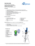
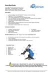
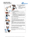
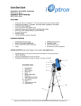
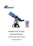
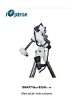
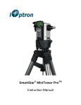
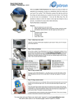
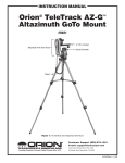
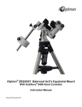
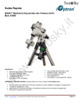
SmartStar®-PR EQ Mount
Manual
www. iOptron. com
WARNING!
NEVER USE A TELESCOPE TO LOOK AT THE SUN!
Looking at or near the Sun will cause instant and irreversible
damage to your eye.
Children should always have adult supervision while observing.
SmartStar® -PR Layout (OTA not included)
Tripod
Set up the Tripod
The SmartStar®-PR comes with a two-inch stainless steel tripod.
The tripod comes fully assembled with a metal plate called the Tripod Head, which holds
the legs together at the top. In addition, there is a central rod that extends down from the
Tripod Head, which attaches the equatorial mount to the tripod. To set up the tripod:
1. Stand the tripod upright and pull the tripod legs apart until each leg is fully
extended. After the tripod is set up you may adjust the height.
2. Loosen the Levers on the Leg Clamps so that the tripod legs can be adjusted.
3. Slide the lower part of the tripod legs out until it is at the height you want.
4. Tighten the Lever on each Leg Clamp to hold the legs in place securely.
Attach the Equatorial Mount and Accessory Tray
The SmartStar®-PR mount is a German equatorial mount that attaches to the Tripod
Head. On one side of the tripod head there is a metal Alignment Peg for aligning the
mount. This side of the tripod should face north when set up for an astronomical
observation. To attach the Equatorial Mount Head:
1. Locate the Azimuth Adjustment Screws on the Equatorial Mount Head.
2. Retract the screws so they no longer extend into the azimuth housing on the
mount. Please do not remove the screws, they are needed later for polar
alignment.
3. Hold the Equatorial Mount Head over the Tripod Head so that the azimuth
housing is above the metal Peg.
4. Place the equatorial mount on the Tripod Head so that the two are flush.
5. Tighten the knob (attached to the Central Rod) on the underside of the Tripod
Head to hold the Equatorial Mount Head firmly in place.
6. Slide the Accessory Tray so that the tray is pushing against the inside of the tripod
legs and the Central Rod goes through the tray.
7. Thread the Accessory Tray Knob on to the Central Rod and tighten.
EQ Mount Head
Since the fully assembled telescope can be quite heavy, position the
mount so that the polar axis is pointing towards north before the OTA
and counterweight are attached. This will make the polar alignment
procedure easier.
Install the Counterweight
The telescope needs to be balanced by the Counterweight to reduce the stress on the gears
and motors. To install the Counterweight bar:
1. Thread the Counterweight Bar Lock Nut onto the threaded end of the
Counterweight Bar.
2. Locate the opening in the Equatorial Mount Head on the DEC axis.
3. Thread the Counterweight Bar into the opening until it is tight.
4. Tighten the Counterweight Bar Lock Nut for extra support.
5. Once the bar is securely in place you are ready to attach the Counterweight.
6. Position the mount so that the Counterweight Bar points toward the ground.
7. Remove the Counterweight Safety Screw on the end of the Counterweight Bar
(the opposite the end that attaches to the mount).
8. Loosen the Locking Screw on the side of the counterweight.
9. Slide the Counterweight onto the shaft.
10. Tighten the Locking Screw on the side of the Counterweight to hold the
Counterweight in appropriate place.
11. Put back the Counterweight Safety Screw.
Attach an OTA to the Mount
The optical tube attaches to the mount via a 1.75” Dovetail Plate. The Dovetail Plate
mounts along the bottom of a telescope tube. To avoid any damage to the OTA and the
mount, before you attach an optical tube, make sure that the declination and right
ascension clutch knobs are tight. To mount the telescope tube:
1. Loosen the Dovetail Locks on the side of the Telescope-Mounting Platform. This
allows you to slide the Dovetail Plate onto the mount.
2. Slide the Dovetail Plate on the telescope tube into the Mounting Platform of the
mount.
3. Tighten the Dovetail Locks on the side of the mounting platform to hold the telescope
in place. Tighten the big lock first, then the smaller one.
Balance in R.A.
To reduce the excessive stress on the mount and motor, the telescope should be properly
balanced around both R.A. and DEC axes. Proper balancing is crucial to both accurate
tracking and protection of the mount. Both the R.A. and DEC axis have lock levers to
clutch down each axis of the telescope. To loosen the clutches on the telescope, rotate the
lock levers counterclockwise.
1. Verify that the telescope is securely attached to the Telescope-Mounting Platform.
2. Loosen the R.A. Lock Lever and position the telescope off to one side of the mount.
The Counterweight Bar will extend horizontally on the opposite side of the mount.
3. Release the telescope slowly to see which way the telescope “rolls.”
4. Loosen the Locking Screw on the side of the counterweight so it can be moved the
length of the Counterweight Bar.
5. Move the Counterweight to a position where it balances the telescope (i.e., the
telescope does not move when the R.A. clutch knobs are loose).
6. Tighten the Screw on the Counterweight to hold it in place.
The above instructions describe a perfect balancing. In fact, there should be slight
imbalance to ensure the best tracking. When the scope is on the west side of the mount
the counterweight should be slightly imbalanced to the counterweight bar side. And when
the tube is on the east side of the mount there should be a slight imbalance toward the
telescope side. This is done so that the worm gear is pushing against a slight load. The
amount of the imbalance is very small. When doing astrophotography, this balance
process should be done for the target area where the telescope is pointing to increase
tracking accuracy.
Balance in DEC
Even though the mount does not track in DEC, the telescope should still be balanced in
DEC to prevent any sudden motions when the DEC lock lever is loose. To balance the
telescope in DEC:
1. Loosen the R.A. Lock Lever and rotate the telescope so that it is on one side of the
mount (please refer to “Balancing the Mount in R.A.”).
2. Tighten the R.A. Lock Lever to hold the telescope in place.
3. Loosen the DEC Lock Lever and rotate the telescope until the tube is parallel to
the ground.
4. Release the tube slowly to see which way it rotates around the declination axis.
5. Slightly loosen the knobs that hold the telescope to the Mounting Platform and
slide the telescope either forward or backward until it remains stationary when the
DEC clutch is loose. Do NOT let go the telescope tube while the knob on the
Mounting Platform is loose. It may be necessary to rotate the telescope so that the
Counterweight Bar is pointing down before loosening the mounting platform
screw.
6. Tighten the knobs on the Telescope-Mounting Platform to hold the telescope in
place.
Just like R.A. balancing, these are general balance instructions and will reduce excessive
stress on the mount. When doing astrophotography, this balance process should be done
for the target area where the telescope is pointing to.
Adjust the Mount
To track celestial objects accurately, the telescope’s axis of rotation must be parallel to
the Earth’s axis of rotation. This is called the polar alignment. The polar alignment is not
achieved by moving the telescope in either R.A. or DEC. This is done by adjusting the
telescope horizontally (azimuth) and vertically (altitude). More details of polar alignment
is described later.
Adjust the Mount in Altitude
To increase the latitude of the polar axis, tighten the Rear Latitude Adjustment Screw
and loosen the Front Screw (if necessary).
To decrease the latitude of the polar axis, tighten the Front (under the Counterweight
Bar) Latitude Adjustment Screw and loosen the rear screw (if necessary).
The latitude adjustment on the SmartStar®-PR mount has a range from approximately 30°
to 60°.
You should always make final adjustments in altitude by moving the mount against
gravity (i.e. using the Rear Latitude Adjustment Screw to raise the mount). To do this you
should loosen both Latitude Adjustment Screws and manually push the front of the mount
down as far as it goes. Then tighten the Rear Adjustment Screw to raise the mount to the
desired latitude.
For Advanced users, it may be helpful to remove the Front Latitude Adjustment Screw
completely. This will allow the mount to reach lower latitudes without the screw coming
into contact with the R.A. motor assembly. To remove the latitude screw, first use the
rear screw to raise the mount head all the way up. Then remove the Front Latitude Screw
completely. Now you should be able to manually move the Mount Head all the way to its
lowest latitude. Now raise the mount to your desired latitude using only the rear screw.
Adjust the Mount in Azimuth
For rough adjustments in azimuth, simply pick up the telescope and tripod and move it.
For fine adjustments in azimuth:
Turn the Azimuth Adjustment Knobs located on both sides of the azimuth housing.
While standing behind the telescope, the knobs are in the front of the mount.
o Turning the Right Adjustment Knob clockwise moves the mount toward the
right.
o Turning the Left Adjustment Knob clockwise moves the mount to the left.
Both screws push the Peg on the Tripod Head. This means you have to loosen one screw
when tightening the other. The screw that holds the equatorial mount to the tripod may
have to be loosened slightly too.
Keep in mind that adjusting the mount is done during the polar alignment process only.
Once polar aligned, the mount should NOT be moved. Pointing the telescope to a target
is done by moving the mount in right ascension and declination as described earlier in
this manual.
Attach the Coiled Cables
There are two Port B’s which are equivalent.
There are three Port A’s which are equivalent to
each other, too.
Use one of the coiled cables to connect one Port A
and one Port B. Plug the cable from the 8401
controller to one of the Port A’s. Extra ports are
reserved for other future accessories.
Now plug in the AC adapter, or DC adapter, and
turn on the power.
If you R.A. and DEC motors are not installed on
the mount, please refer to the installation
instructions here:
http://www.ioptron.com/manuals/GoToNovaKitManual.pdf
The GOTONOVATM 8401 Controller Layout:
The 8401 GoToNovaTM hand held controller is the standard controller for SmartStar®-PR.
The user interface is simple and easy to learn.
LCD Display: 8-line big screen, it displays all the information
Back Key: Move back to the previous screen.
Menu Key: Return to the Main Menu.
Enter Key: Confirms an input, goes to the next menu, selects a choice, slews the
telescope to a selected object.
Arrow Keys: Moves the cursor, moves the telescope in a specific direction.
Number Keys: Adjusts numerical values.
Speed Key: Adjusts the speed.
Light Key: Turns on/off the red LED reading light on the back of the controller.
Help Key: For help.
The LCD Display:
Target Right Ascension
Target Declination
Right Ascension
GPS Status
Slew Speed
Declination
Tracking Speed
Local Star Hour
Altitude
Azimuth
Local Date and Time
N/S Hemisphere
GPS status: When the power is turned on, it shows “GPS ON”. When it finds the satellite
and receives GPS signal, it shows “GPS OK”.
Slew speed: It has 9 speeds: 1X, 2X, 8X, 16X, 64X, 128X, 256X, 512X, MAX
Tracking speed: It has 4 speeds: Cel(celestial), Sol(Solar), Lun(Lunar), Def(user defined)
SmartStar®-PR Basic Setups and Functions
1. Set Up Time Zone (Main Menu/Set up Controller/Set up Site)
Turn on the power, push MENU, from the main menu, scroll down and select “Set
up controller”
Select and slew
Sync. to target
Electronic focuser
Set up controller
Align
PEC option
Set up Tracking
User objects
Push ENTER. Scroll down and select “Set up site”
Set
Set
Set
Set
Set
Set
Set
Set
up Local Time
up site
N/S hemisphere
display contrast
Eyepiece light
Backlash
anti-backlash
Key Beep
Push ENTER. Push left arrow button, move the cursor to the bottom of the screen
to set the time zone information.
All the time zones in North America are behind UT (universal time), so make sure
it shows “behind” instead of “ahead of” UT. When the cursor is in that position,
use up or down arrow to toggle between “behind” and “ahead of”. Then use the
left button to move the cursor to the number of minutes behind UT. This number
is calculated by multiplying the regular time offset (in hours) to 60. For other
parts of the world, you can find out your “time zone” information here:
http://www.timeanddate.com/worldclock/
DO NOT COUNT DAYLIGHT SAVING TIME. Use the standard time offset.
For example, the time offset of Eastern Time Zone is UTC-5 during standard
time, so the number of minutes is 5x60=300 Min. behind UT. Even during
daylight saving time in the summer, your time zone is still “300 Min. behind UT”,
NOT “240 Min. behind UT”.
In this step “time zone” is not related to time. It is related to degrees away from
UT. The internal computer adjusts star locations based on where you are in
relation to UT—not when you are.
To adjust minutes behind or ahead of UT, move the cursor to each digit and use
the number keys to input number directly.
When the number is correct, push ENTER and go back to the previous screen. Do
not worry about longitude and latitude numbers; they will be set by internal GPS.
Set up site info:
Longitude:
W071d27m47s
Latitude:
N42d15m40s
300 Min. behind
of
UT
2. Set Up Daylight Saving Time (Main Menu/Set up Controller/Set up Local Time)
Scroll up and select “Set up local Time”
Set
Set
Set
Set
Set
Set
Set
Set
up Local Time
up site
N/S hemisphere
display contrast
Eyepiece light
Backlash
anti-backlash
Key Beep
Set local time:
2008-06-01 11:55:09
Daylight Saving Time √
Use the left arrow to move the cursor to the bottom of the screen, use the up or
down button to toggle between √ and X. √ means “yes, now it is daylight saving
time”. X means “no, now it is regular time”.
Push ENTER to go back the previous screen. Do not worry about the date and
time right now; they will be set by the internal GPS.
3. Set mount type (Main Menu/Set up Controller/Set Mount Type)
Scroll down and select “Set Mount Type”
Set
Set
Set
Set
Set
Set
Set
Set
up site
N/S hemisphere
display contrast
Eyepiece light
Backlash
anti-backlash
Key Beep
Mount Type
SmartStar®-PR is an EQ mount, so select Equatorial mount and push ENTER.
Equatorial Mount
Alt/Azi Mount
4. Time, location and GPS
Push BACK twice and go back to the starting screen. Turn off the power. Wait a
few seconds and turn the power back on. You will see “GPS ON” in the upperright corner of the screen. After about a minute, when it finds the satellite and
receives GPS signal, you will see “GPS OK”. Local time, longitude and latitude
will then be set automatically. Double check date and time make sure they are
correct. If they are not, then re-do steps 1 through 3. Make sure you see “EQ” in
the lower right corner indicating “Equatorial”. If it shows “A/A” then you need to
reset the mount type in step 3.
5. Tighten all the screws and locks. Double check the bubble and south mark. Now
you are ready to use the SmartStar®-PR.
6. Align (Main Menu/Align)
The system provides “one-star align”, “two-star align” and “three-star align”
From the main menu, select “Align”. Select “one-star align”. Use “UP” and
“DOWN” arrow buttons to select a star and press ENTER. A list of the align stars
is computed based on your local time and location. Use arrow buttons to move the
telescope and center the star in your eyepiece. You can use SPEED button to
change speed.
Press ENTER when finished. If your setups to now are quite accurate, “one-star
align” should be sufficient. To increase the accuracy you may choose to do twostar or three-star align.
“Two-Star Align” will increase the accuracy of alignment, but it requires a wider
view of the sky, since the two align stars need to be far apart. Select “Two-star
align” in the Align menu. When you finish the first star, the system will prompt
you to choose the second star. If the star you choose is too close to the first one,
the system will let you choose another one. When you aligned with the second
star, two-star align is finished.
“Three-Star Align” will increase the accuracy even higher and requires an even
wider view of the sky. This basically asks you to choose yet another third star to
align after two-star align.
7. Select and Slew (Main Menu/Select and Slew)
Now you can select any object in the database, and SmartStar®-PR will get you
there (if it is above the horizon). For more details, check the section on
“SmartStar®-PR Select and Slew”
8. The Database Contents
The numbers of the objects in the database are listed below:
Solar system: 10
Deep sky objects:
Named Deep sky Objects: 76
Messier Catalog: 110
NGC IC Catalog: 5386
UGC Catalog: 12939
MCG Catalog: 29004
Caldwell Catalog: 109
Abell Catalog: 2712
Herschel Catalog: 400
Comets: 190
Asteroids: 4096
Stars:
Named Stars: 191
Double Stars: 40
GCVS Variable Stars: 38624
SAO Catalog: 26584
Constellations: 88
User Objects: 256
9. Firmware Upgrade
Firmware in the controller can be upgraded from you PC. New firmware versions
are released to fix bugs and add new functions. For latest firmware release and
instructions, please check: http://www.ioptron.com/support.aspx?catalog=28
Find Polaris
Polaris is less than one degree from the celestial pole. Finding Polaris helps you locate
the celestial pole. Although this is not a perfect alignment, it does get you quite close to
the pole.
1. Set the telescope up so that the polar axis is pointing north.
2. Loosen the DEC Lock Lever and move the telescope so that the tube is parallel to the
polar axis. When this is done the declination setting circle should read +90°. If the
declination-setting circle is not aligned then move the telescope so that the tube is
parallel to the polar axis.
3. Adjust the mount in altitude and azimuth until Polaris is in the field of view of the
Finder Scope.
4. Center Polaris in the field of the Eyepiece using the fine adjustment controls on the
mount.
Please remember: during polar alignment, do not move the telescope in R.A. or
DEC. You should not move the telescope itself, but only the polar axis. The telescope
is used to see where the polar axis is pointing.
This gets you close to the pole but not directly on it. The following two methods help
improve your accuracy for more serious observations and photography.
Find the N.C.P.
N.C.P. stands for North Celestial Pole. In each hemisphere, there is a point in the sky
around which all the other stars appear to rotate; those points are called the celestial
poles. When the telescope’s
polar axis is aligned with
celestial pole, it is parallel to
the earth’s rotational axis.
Polar alignment usually
requires that you know the
stars in the polar area. In the
northern hemisphere, Polaris
is only one degree away from
the celestial pole. Polaris is
visible by the naked eye
during clear nights.
DEC Drift Method
Declination (DEC) drift method is a standard method for polar alignment. You can find a
lot of references on the Internet by googling the term. This method might seem simple
and straightforward at first look, but it is actually very time consuming if you don’t have
a lot of experience with it. You are strongly suggested to do a lot of homework before
trying it out. It is also suggested that you work with people who have had a lot of
experience -- at least for the first couple of nights.
With DEC Drift Method, you monitor the drift of each star which tells you how far away
you are from the celestial pole.
To perform a DEC drift, you should first perform the steps previously mentioned (Find
Polaris and Find NCP).
You need to pick two bright stars to do the DEC drift. One should be close to the eastern
horizon and the other due south near the meridian. Both stars should be near the celestial
equator (i.e., 0° declination). Monitor the drift of each star one at a time and in DEC only.
While monitoring the star on the meridian, any misalignment in the east-west direction is
revealed. While monitoring a star near the east/west horizon, any misalignment in the
north-south direction is revealed. It is helpful to have an illuminated eyepiece to help you
recognize any drift. To fine tune the alignment, a Barlow lens is recommended since it
increases the magnification and reveals any drift faster. When looking due south, insert
the diagonal so the eyepiece points straight up. Insert the cross hair eyepiece and align the
cross hairs so that one is parallel to the declination axis and the other is parallel to the
right ascension axis. Move your telescope manually in R.A. and DEC to check
parallelism.
Choose your star near where the celestial equator and the meridian meet. The star should
be approximately within half an hour of the meridian and within five degrees of the
celestial equator. Center the star in the field of your telescope and monitor the drift in
declination.
If the star drifts south, the polar axis is too far east.
If the star drifts north, the polar axis is too far west.
Make the appropriate adjustments to the polar axis to eliminate any drift. Once you have
eliminated all of the drift, move to the star near the eastern horizon. The star should be 20
degrees above the horizon and within five degrees of the celestial equator.
If the star drifts south, the polar axis is too low.
If the star drifts north, the polar axis is too high.
The two stars in the front of the bowl of the Big Dipper point to Polaris, which is less
than one degree from the true (north) celestial pole. Cassiopeia, the “W” shaped
constellation, is on the opposite side of the pole from the Big Dipper. The North
Celestial Pole (N.C.P.) is marked by the “+” sign.
Again, make the appropriate adjustments to the polar axis to eliminate any drift.
Unfortunately, the latter adjustments interact with the prior adjustments ever so slightly.
So, repeat the process again to improve the accuracy checking both axes for minimal
drift. Once the drift has been eliminated, the telescope is very accurately aligned. You
can now do prime focus deep-sky astrophotography for long periods.
SmartStar®-PR Select And Slew
After you have finished the set up and align steps in chapter 1 go to the main menu.
Select “Select and slew.” Now you can select any celestial objects in the database and
GoToNovaTM will take you there—whether it is a star, a planet, an asteroid, a comet or a
galaxy.
Check astronomy books and magazines such as “Sky and Telescope.” Familiarize
yourself with the names in the night sky. Use the arrow buttons to move your cursor and
press ENTER to select an object.
For a star check list, please go to: http://www.ioptron.com/manuals/starlist.pdf
Planets, sun, moon
This menu includes the Sun, the Moon, Mercury, Venus, Mars, Jupiter, Saturn, Uranus,
and Neptune.
WARNING: NEVER LOOK DIRECTLY AT THE SUN WITH THE NAKED EYE
OR WITH A TELESCOPE (UNLESS YOU HAVE THE PROPER SOLAR
FILTER). PERMANENT AND IRREVERSIBLE EYE DAMAGE MAY RESULT.
Deep Sky Objects
This menu includes objects outside our Solar system such as galaxies, star clusters,
quasars, nebulae, etc.
Named Deep Sky Objects
This menu contains 60 named deep sky objects. If you know the names of the objects you
can use this menu.
Messier Catalogue
Contains 110 objects from the Messier catalogue.
NGC-IC Catalogue
Contains 7840 objects from the NGC-IC catalogue.
UGC Catalogue
Contains 12,939 objects from the UGC catalogue.
MCG Catalogue
Contains 29,004 objects from the MCG catalogue.
Caldwell Catalogue
Contains 109 objects from the CaldWell catalogue.
Abel Catalogue
Contains 2712 objects from the Abel catalogue.
Herschel Catalogue
Contains 400 objects in Herschel catalogue.
Comets
Contains up to 256 comets.
Asteroids
Contains up to 4096 asteroids.
Stars
Named Stars
Contains 191 stars.
Constellations
Contains 88 constellations.
Double Stars
Contains 40 double stars.
Variable Stars
Contains 38,624 variable stars.
SAO Bright Stars
Contains up to 26,584 SAO bright stars.
Constellations
Contains 88 constellations.
User Objects
User defined objects. User can define up to 128 objects
Enter R.A. DEC.
In Equatorial mode the user can target a location by specifying its RA (Right Ascension)
and DEC (Declination). Use the arrow buttons to move the cursor and adjust the values.
Press ENTER.
Other SmartStarTM PR Functions
Main Menu/Sync To Target
Matches the telescope's current equatorial coordinates to Target Right
Ascension and Declination.
Main Menu/Electric Focuser
If you have an electric focuser in your system use this option to adjust the
focuser.
Main Menu/PEC option
If your telescope is equipped with Periodic Error Correction use this option
to adjust Periodic Error Correction.
Main Menu/Set up tracking
Set up tracking speed.
Main Menu/User objects
Add, edit or delete user objects.
Main Menu/Auto guide
If your telescope is equipped with auto guide use this option.
Main Menu/Park Scope
Park your telescope.
Main Menu/To Park position
Move your telescope to park position.
IOPTRON TWO YEAR TELESCOPE, MOUNT, AND CONTROLLER WARRANTY
A. iOptron warrants your telescope, mount, or controller to be free from defects in materials and workmanship for two years. iOptron will
repair or replace such product or part which, upon inspection by iOptron, is found to be defective in materials or workmanship. As a
condition to the obligation of iOptron to repair or replace such product, the product must be returned to iOptron together with proof-ofpurchase satisfactory to iOptron.
B. The Proper Return Authorization Number must be obtained from iOptron in advance of return. Call iOptron at 1.781.935.2800 to receive
the number to be displayed on the outside of your shipping container.
All returns must be accompanied by a written statement stating the name, address, and daytime telephone number of the owner, together
with a brief description of any claimed defects. Parts or product for which replacement is made shall become the property of iOptron.
The customer shall be responsible for all costs of transportation and insurance, both to and from the factory of iOptron, and shall be
required to prepay such costs.
iOptron shall use reasonable efforts to repair or replace any telescope, mount, or controller covered by this warranty within thirty days of
receipt. In the event repair or replacement shall require more than thirty days, iOptron shall notify the customer accordingly. iOptron
reserves the right to replace any product which has been discontinued from its product line with a new product of comparable value and
function.
This warranty shall be void and of no force of effect in the event a covered product has been modified in design or function, or subjected to
abuse, misuse, mishandling or unauthorized repair. Further, product malfunction or deterioration due to normal wear is not covered by this
warranty.
IOPTRON DISCLAIMS ANY WARRANTIES, EXPRESS OR IMPLIED, WHETHER OF MERCHANTABILITY OF FITNESS FOR A
PARTICULAR USE, EXCEPT AS EXPRESSLY SET FORTH HERE. THE SOLE OBLIGATION OF IOPTRON UNDER THIS LIMITED
WARRANTY SHALL BE TO REPAIR OR REPLACE THE COVERED PRODUCT, IN ACCORDANCE WITH THE TERMS SET FORTH
HERE. IOPTRON EXPRESSLY DISCLAIMS ANY LOST PROFITS, GENERAL, SPECIAL, INDIRECT OR CONSEQUENTIAL DAMAGES
WHICH MAY RESULT FROM BREACH OF ANY WARRANTY, OR ARISING OUT OF THE USE OR INABILITY TO USE ANY IOPTRON
PRODUCT. ANY WARRANTIES WHICH ARE IMPLIED AND WHICH CANNOT BE DISCLAIMED SHALL BE LIMITED IN DURATION TO
A TERM OF TWO YEARS FROM THE DATE OF ORIGINAL RETAIL PURCHASE.
Some states do not allow the exclusion or limitation of incidental or consequential damages or limitation on how long an implied warranty
lasts, so the above limitations and exclusions may not apply to you.
This warranty gives you specific legal rights, and you may also have other rights which vary from state to state.
iOptron reserves the right to modify or discontinue, without prior notice to you, any model or style telescope.
If warranty problems arise, or if you need assistance in using your telescope, mount, or controller contact:
iOptron Corporation
Customer Service Department
6X Gill Street
Woburn, MA 01801
Tel. (781) 935-2800
Fax. (781) 935-2860
Monday-Friday 9AM-5PM EST
NOTE: This warranty is valid to U.S.A. and Canadian customers who have purchased this product from an authorized iOptron dealer in the
U.S.A. or Canada or directly from iOptron. Customers outside the U.S.A. and Canada must contact their iOptron Distributor or Authorized
iOptron Dealer in the specific country for any warranty service if provided.