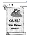
1
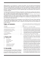
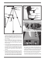
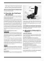
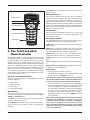
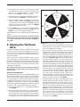
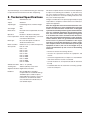
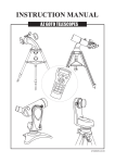
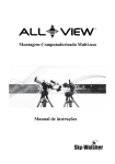
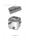
instruction Manual
Orion® TeleTrack AZ-G™
Altazimuth GoTo Mount
#9481
¼"-20 L-bracket
Altazimuth Fork Arm Head
Hand Controller
Tripod
Figure 1: The TeleTrack AZ-G Altazimuth GoTo Mount
Customer Support (800)‑676-1343
E-mail: [email protected]
Corporate Offices (831)‑763-7000
Providing Exceptional Consumer Optical Products Since 1975
89 Hangar Way, Watsonville, CA 95076
IN 348 Rev. A 11/08
Congratulations on your purchase of a quality Orion product. Your new TeleTrack AZ-G Altazimuth
GoTo Mount allows high performance support for terrestrial or astronomical observations. The TeleTrack
AZ-G is an “altazimuth” type of mount which can move in both altitude (up and down) and azimuth (left
and right) with respect to the ground. Designed for use during day or night, your TeleTrack AZ-G mount
features a smooth altazimuth fork arm head, adjustable tripod, and multi-function hand controller for
convenient operation.
The TeleTrack AZ-G Altazimuth GoTo Mount is designed for small telescopes, spotting scopes and cameras. The weight of the instrument supported by the mount should not exceed 9 lbs. The mount will also
work best with short tube optical systems no longer than 15" (380mm).
This precision mount will locate and automatically slew to thousands of fascinating celestial denizens
including the planets of our solar system, our Moon, galaxies, nebulae, stars, and star clusters. With a
little practice, you’ll find that the TeleTrack AZ-G Mount is an invaluable tool for getting the most out of
your astronomical observing sessions.
These instructions will help you set up and properly use your TeleTrack AZ-G mount. Please read them
over thoroughly before getting started. It may take a few observing sessions to become familiar with
all the features of the TeleTrack AZ-G mount, so keep this manual handy until you have mastered your
mount’s operation.
Table of Contents
1. Parts List . . . . . . . . . . . . . . . . . . . . . . . . . . . . . . . . . . . . . 2
can be used to transport the mount. In the unlikely event that
you need to return the mount, you must use the original packaging.
2. Assembly . . . . . . . . . . . . . . . . . . . . . . . . . . . . . . . . . . . . . 2
Refer to Figures 1, 2, and 3 during assembly.
3. Powering the TeleTrack AZ-G Mount . . . . . . . . . . . . . . . . 4
1. Remove the tripod from its box. Note that each leg has
two telescoping sections. To extend each leg, loosen the
leg lock lever by rotating it counterclockwise, then extend
the leg. When it has been extended to the desired length,
rotate the leg lock lever clockwise until tight. Before placing
an instrument on the mount, it is a good idea to press down
on the tripod to make sure the legs are locked securely
and will not give way under the instrument’s weight.
4. Attaching a Telescope or Camera . . . . . . . . . . . . . . . . . . 4
5. The TeleTrack AZ-G Hand Controller . . . . . . . . . . . . . . . . 5
6. Aligning the TeleTrack AZ-G . . . . . . . . . . . . . . . . . . . . . . 6
7. Care and Cleaning . . . . . . . . . . . . . . . . . . . . . . . . . . . . . . 9
8. Technical Specifications . . . . . . . . . . . . . . . . . . . . . . . . . 10
9. Appendices . . . . . . . . . . . . . . . . . . . . . . . . . . . . . . . . . . 12
Qty.
Description
2. The TeleTrack AZ-G’s tripod has a wide stance for
enhanced stability. The widest stance is achieved when
the leg brace is as far down as it will go on the elevator
shaft housing. The leg brace lock knob should be tightened to secure the stance.
1
Hand controller
1
Hand controller cable
1
Adjustable tripod
1
Fork arm
1
L-bracket with ¼"-20 adapter
1
Computer Interface cable
1
Hand controller bracket
1. Parts List
2. Assembly
The TeleTrack AZ-G Mount comes partially assembled and
can become operational in a matter of minutes. It is packaged
in one reusable shipping carton. Remove all parts from the
box. Make sure all the parts listed In Section 1 are present.
Remember to save all the shipping containers so that they
2
If you are using the tripod in a confined space, the stance
can be narrowed by loosening the leg brace lock knob and
pushing the legs closer together. Re-tighten the lock knob
to secure the legs in the new position. Be aware that the
tripod will become more prone to tipping as its stance is
narrowed. Be very careful when mounting an instrument
with an offset, or unwieldy, center of gravity on the tripod,
especially if it begins to approach the 9 lb. weight limit.
3. With the tripod secure, the fork arm can be easily attached
using the 3/8"-16 threaded post on top of the tripod mounting platform. There is also a 3mm socket-head cap screw
on the underside of the mounting platform that helps to
lock the fork arm in place. Loosen, but do not remove,
this allen-screw so that the fork arm will not contact the
lock-screw while attaching the head. Hold the fork arm so
its circular base is facing downward and place it on the
3/8"-16 threaded post gently. Rotate the entire fork arm
3/8"-16
Threaded Post
Dovetail
Lock
Knob
Elevator Shaft
Hinged
Hand Crank
Dovetail
Mount
¼"-20
L‑bracket
Bubble Level
Leg Brace
Lock Knob
Battery
Compartment
Leg Lock
Levers
Battery
Compartment
Latch
Circular Base
Figure 3: The TeleTrack AZ-G GoTo Mount Fork Arm
Leg Brace
RJ-45 (to mount)
RJ-12 (to PC)
12V DC power jack
Figure 4a: Hand controller outlets
12V DC
IN
Figure 2: The TeleTrack AZ-G Tripod
12V DC
OUT
assembly clockwise until it threads completely onto the tripod’s 3/8"-16 threaded post, and rests securely on the tripod’s mounting platform. Now tighten the lock-screw from
underneath the mounting platform to provide extra stability
to the assembly.
4. There is a bubble level at the base of the fork arm. To
make the fork arm level, simply adjust each tripod leg up
or down, one at a time, until the bubble rests in the central
black circle of the level. Proper leveling of the tripod will
maximize stability.
5. To raise or lower the TeleTrack AZ-G Mount’s fork arm to
a comfortable height, first loosen the elevator lock knob
on the tripod, then use the hinged hand crank to move
the elevator shaft up or down. Re-tighten the elevator
lock knob to secure the instrument at the new height. The
mount will be most stable when the elevator shaft is not
extended.
6. The TeleTrack AZ-G hand controller cable has a large,
modular connector (RJ-45) and a smaller, modular connector (RJ-12). First, plug the large modular connector
of the hand controller cable into the corresponding jack
on the hand controller (Figure 4a) until it clicks into place.
The smaller jack is used to interface the TeleTrack AZ-G
Hand Controller Jack
Aux. Jack
Power Switch
Figure 4b: Connector Ports on the TeleTrack AZ-G GoTo Mount
hand controller with a computer running planetarium software (optional). The 12V power jack on the hand controller allows independent use of the TeleTrack AZ-G hand
controller. This is helpful for users who wish to browse the
object database or when performing firmware upgrades.
7. Attach the other end of the connector into the jack labeled
“HC” on the TeleTrack AZ-G mount head (Figure 4b).
The TeleTrack AZ-G hand controller allows direct access
to all of the user-friendly motion controls of the mount and
3
a database with a wide range of preset objects. The hand
controller display is backlit for comfortable viewing. Make
sure not to confuse the “HC” jack with the “AUX” jack. The
“AUX” jack is not used for normal operation of the mount.
Dovetail
Plate
Note: Do not attempt ot reposition the altitude or azimuth
of the mount by hand! Doing so can damage the gears
and motors within the mount.
3. P
owering the TeleTrack
AZ-G Mount
¼"-20
Threaded Post
Foam
Padded base
The TeleTrack AZ-G mount can be powered by 8 AA batteries,
an optional 12V DC power supply, or an optional AC adapter.
Tightening
Lever
Powering by AA Batteries
For maximum portability, the TeleTrack AZ-G mount features a
battery compartment that holds eight (8) AA alkaline batteries
(user supplied). To open the compartment, press down on the
black battery compartment latch (see Figure 3) and gently lift
the cover off. You will find two separate battery holders that
hold 4 AA batteries each. For easiest installation, detach each
battery holder and insert your AA batteries until each holder
is full. Be sure to orient the batteries as indicated on the battery holder. Reattach the filled battery holders securely using
the snap connectors and close the battery compartment by
pressing its cover down gently until its latch clicks. Power the
TeleTrack AZ-G on by pressing the red on/off switch to the “on”
position.
Knurled Knob
Powering by External Power Source
Portable Battery
For optimal results, we recommend using a portable rechargeable battery like the Dynamo Pro available from Orion. These
12V DC batteries will power the mount far longer than standard AA batteries. Make sure your rechargeable battery is tip
positive and capable of producing continuous current with a
minimum of 1 amp.
Figure 5: The TeleTrack AZ-G GoTo Mount ¼"-20 L-bracket
or camcorders. It accepts a DC power plug (tip positive) and
provides 12V DC power output. To power a 12V accessory
with the TeleTrack AZ-G, simply plug the accessory’s 12V DC
power cable into the “DC OUT” (Figure 4b) jack on the side of
the mount.
Caution: Never plug an external power supply cord into
the “12V DC OUT” jack accidentally. This may damage the
AA batteries inside the battery compartment, and possibly damage the mount itself.
4. Attaching a Telescope or
Camera
USING THE L-BRACKET
Your TeleTrack AZ-G Mount comes with a convenient L-bracket
(Figure 5) that provides coupling to the mount with the standard ¼"-20 threaded hole found on most cameras, camcorders, and many telescopes.
If you are using a portable battery like the Orion Dynamo
Pro, use the Dynamo’s supplied 12V DC power cable (cigarette lighter plug on one end, standard 12V DC power plug
on the other end) to connect the battery to the 12V “DC IN”
(Figure 4b) power jack on the side of the mount. Make sure
the Dynamo’s power switch is in the “off” position when connecting cables. Power the TeleTrack AZ-G on by pressing the
red on/off switch to the “on” position
Attaching an Instrument to the L-bracket
With the foam-padded base of the L-bracket facing upward,
gently place the ¼"-20 threaded hole in your optical instrument onto the ¼"-20 threads on the L-bracket. Turn the black
knurled knob so the ¼"-20 threaded post completely engages
the ¼"-20 threaded hole in your telescope, spotting scope, or
camera. Tighten by rotating the tightening lever on the underside of the L-bracket until secure.
AC Adapter
Attaching the L-bracket to the Mount
The L-bracket has a short dovetail plate that slides into the
corresponding dovetail mount on the fork arm. The other section of the L-bracket has a foam-padded base for your telescope or camera.
In addition, the mount can be powered by an optional AC
adapter rated at 12V DC, 1000mA, tip positive. Plug the adapter cord into the “DC IN” power jack for operation. Power the
TeleTrack AZ-G on by pressing the red on/off switch to the “on”
position.
Power Output
Unlike many mounts in its class, the TeleTrack AZ-G Mount
will provide power output for accessories like digital cameras
4
Insert the dovetail plate of the L-bracket into the dovetail
mount, making sure that it is oriented as shown in Figure 3.
Then tighten the dovetail lock knob until snug.
The SETUP button is a quick hot key that takes you to the
Setup submenu
Display screen
Mode buttons
Directional buttons
Directional Buttons
The directional buttons allow the user to have complete
control of the mount at almost any step in operation. These
controls are locked out when the telescope is slewing to an
object. The directional buttons are very helpful when initially
aligning the TeleTrack AZ-G, centering objects in the eyepiece
field of view, and manual guiding. The left and right directional
buttons can also be used to move the text cursor when entering data on the hand controller.
Dual purpose buttons
Scroll Buttons
The up and down scroll buttons allow you to scroll up and
down within the menu tree or selections displayed on the
hand controller screen.
Scroll buttons
Dual Purpose Buttons
The Dual Purpose buttons serve two distinct purposes. They
are used for data entry and as quick reference keys.
TOUR button: Takes you on a preset tour of the best night sky
objects visible
Figure 6: The TeleTrack AZ-G hand controller
5. The TeleTrack AZ-G
Hand Controller
The TeleTrack AZ-G is a precision-engineered alt-azimuth
mount that provides easy, computerized location of thousands
of night sky objects such as planets, nebulae, star clusters,
galaxies, and more for viewing through your telescope. The
TeleTrack AZ-G hand controller and internal dual-axis motors
allow you to automatically point your telescope at a specific
object, or tour the skies with push-button simplicity. The userfriendly menu allows auto-slewing to over 42,900 objects.
Even inexperienced astronomers will find themselves quickly
mastering the variety of features the TeleTrack AZ-G offers in
just a few observing sessions.
Functions of the Hand Controller
There are four main categories of control buttons on the hand
controller (Figure 6):
1. Mode buttons
2. Directional buttons
3. Scroll buttons
4. Dual Purpose buttons
Mode Buttons
The three mode buttons are located at the top of the controller, directly below the LCD display. They include the ESC,
ENTER, and SETUP buttons:
The ESC button is used to escape from a certain command or
go back a level in the menu tree.
The ENTER button is used to select the functions and submenus in the menu tree, and to confirm certain functional
operations.
RATE button: Changes the speed of the motors when the
directional buttons are pressed. There are 10 speeds to choose
from, with 0 being the slowest and 9 being the fastest.
UTILITY button: “Hot Key” access to the Utility Functions
menu that provides useful tools in configuring your mount.
USER button: Gives access to up to 25 user-defined coordinates
ID button: Identifies the object the mount is currently pointing
to.
NGC, IC, M, Planet, and Object buttons: Allows direct access
to database of over 42,900 objects.
Initial Setup
1. Turn on the power switch on the mount
2. The initial screen displayed on the hand controller is the
Version Screen. Press ENTER to proceed.
Note: The hand control’s backlit display will become more
dim and the illuminated buttons will turn off if left idle for 30
seconds. Pressing any button will illuminate the display.
3. Enter the telescope’s current latitudinal and longitudinal
position using the numeric keypad and scroll buttons. First
enter the longitudinal coordinate and hemisphere (W or
E), followed by the latitudinal coordinate and hemisphere
(N or S). If you do not know the latitude and longitude
coordinate of your viewing location, consult an atlas or
geographical map of your area. Press ENTER to confirm
your coordinates.
Note: Latitude and longitude coordinates must be entered
in degrees and arcminutes. If your map or atlas gives
coordinates in decimal values (i.e. latitude = 36.95 N) you
must convert into degrees and arcminutes. To do this
simply multiply the decimal value by 60. If your viewing
location is at latitude 36.95 N you would enter a latitude
of 36°57' N [.95x60=57].
5
6. Enter the time zone in which you are observing in hours
(see Appendix A), using the scroll keys and numeric keypad (+ for east of Prime Meridian, - for west of Prime
Meridian). Press ENTER to confirm your choice.
N
NW
7. Enter the date in the following format mm/dd/yyyy using the
numeric keypad. Press ENTER to confirm your choice.
8. Enter your current local time using the 24 hour time mode
(example: 2:00PM = 14:00). Press ENTER to view the time
you entered. If the time is incorrect, press ESC to go back
to the previous screen. If the time is correct, press ENTER
again to proceed to the next step.
9. Press ENTER if you are currently on Daylight Savings
time. Use the scroll button to scroll down to “NO” and press
ENTER if you are not on Daylight Savings Time.
270° –
360°
W
6. Aligning the TeleTrack
AZ-G
In order for the TeleTrack AZ-G to accurately locate and point
to objects in the sky, it must first be aligned on known positions (stars) in the sky. With the supplied information, the
mount can replicate a model of the sky and the movements of
astronomical objects.
There are two ways to align the TeleTrack AZ-G. If you are
new to astronomy, we recommend that you begin with the
Brightest-star Alignment. This method will help you to choose
stars if you are not familiar with the night sky. The description
below will lead you through a step-by-step procedure on how
to perform this alignment.
Note: Before performing any of the alignment methods,
be sure that your finderscope is well aligned with the
telescope tube
Brightest Star Alignment
This method allows you to choose the brightest alignment star
within a selected region of the sky. Even if you are not familiar
with the names of stars in the sky, simply choose the direction
of a visible bright star and the TeleTrack AZ-G can help you
to identify it. This method can also be useful if your visibility
is limited due to obstructions such as trees, hills, or buildings.
Note: Before beginning any alignment procedure be sure that
your finder scope is correctly aligned with your telescope.
1. First select “Brightest Star” as your Alignment Method.
Press ENTER.
2. The hand controller will prompt you to “Select Region”.
Choose the direction which corresponds with where you
see the brightest star in the night sky. It may be helpful to
have a compass for reference during this process. There
are 8 regions to choose from (Figure 7). The direction you
6
NE
0° –
90°
225° –
315°
180° –
270°
The TeleTrack AZ-G is now ready to begin the alignment procedure.
Note: If a mistake was entered into the TeleTrack AZ-G
hand control during the initial setup, press the ESC key
to go back to the previous menu, and press ENTER to
start again.
315° –
45°
SW
45° –
135°
135° –
235°
E
90° –
180°
SE
S
Figure 7: Pie chart of 8 geographical directions.
choose will only affect your alignment star selection; you
will still be able to choose stars to view across the entire
sky once the alignment is complete.
3. After you have selected the region of the sky with the
brightest star, the hand controller will generate a list of the
brightest stars (magnitude 1.5 or brighter) in that region. (If
there are no suitable stars in the direction you have chosen,
the text “No Star Found in the Region” will display. If this
occurs, press ENTER or ESC and select another region of
sky.) Now, use the Scroll keys to scroll through the list of
bright stars. There will only be a few stars, at most, on the
list, and sometimes only one star will be on the list. The
hand controller will display the name and magnitude of the
bright star on the first line, and the approximate position
of the star (based on the time and date entered during
the initial setup) on the second line. The first coordinate
on the second line is an E-W coordinate, and the second
coordinate on the second line indicates degrees above
the horizon. These coordinates provide a simple way to
identify the bright star you have chosen. When you are
confident the hand controller is displaying the name of the
bright star you wish to align on, press ENTER.
4. The mount will not slew to the selected bright star automatically. Instead, the hand controller will direct you to
manually slew the mount to the selected star. The mount
will default to its fastest speed rate for quickest slewing.
Slew the mount using the directional keys and center the
star in the view of your finder scope or reflex sight. Press
ENTER. The hand controller will now instruct you to center
the star in your eyepiece. Once again, use the directional
keys to do this. The mount will default to a slower speed
rate to make it easier to center the star in the narrower
field of view of the eyepiece. When the star is centered in
the eyepiece, press ENTER.
5. The hand controller will now generate a list of stars to
choose as your second alignment star. Scroll through the
list using the Scroll keys (Figure 6) and press ENTER to
choose a second alignment star. The mount will now automatically slew to the selected star and the star should be
somewhere in the field of view of your finder scope. Next,
center the star in your eyepiece with the directional keys
and press ENTER.
The message “Alignment Successful” should display on the
LCD. If so, you may now use your mount to locate stars in the
TeleTrack AZ-G database. If the message “Alignment Failed”
displays, it often means the star positions do not correspond
with the location and date/time information input during setup.
Please check your user input settings before starting again.
Two-Star Alignment
Two-star alignment requires two known alignment stars. If you
know some of the stars in the night sky, this will likely be the
most used alignment method. The description below will lead
you on a step-by-step procedure on how to perform the twostar alignment.
1. Complete the Initial Setup to access the display that states
“Begin Alignment” and choose Yes.
2. The hand controller will provide a lists of stars available in
your current sky for you to choose as the first alignment
star. Using the scroll buttons, choose a star you are familiar with and press ENTER to confirm your choice. The
mount will not slew to the first alignment star automatically, use the directional buttons to manually slew the telescope to point to the star. The displayed coordinates will
not change as the mount slews. Center the star in your
finder scope and press ENTER.
3. The hand controller will prompt you to Center the object.
The rate will automatically slow, allowing you to make fine
adjustments. Movement of the mount will be imperceptible
unless you are looking through the eyepiece. Center the
star in your eyepiece and press ENTER.
4. The Hand controller will now provide you a list to choose
a second alignment star. Use the scroll buttons to select a
star and press ENTER. The mount will slew automatically
to your selection and you will be prompted to center the
star. As described above, the rate will slow so that movement of the mount can only be perceived through the narrow field of view of the eyepiece. Center the star using the
direction keys and press ENTER.
5. Once the two alignment stars have been entered and
alignment is complete the hand controller will display
“Alignment Successful”.
Features of the GoTo Database
Now that you have completed the alignment you are ready to
access all of the advanced functions available in the TeleTrack
AZ-G hand controller.
Object Catalog
The TeleTrack AZ-G boasts a vast database of over 42,900
object coordinates and information. The database contains
the following catalogs:
Solar System: The other 8 planets of our solar system, and
our planets’ Moon.
Named Star: A list of 100 popular known stars
NGC: 7,840 of the brightest deep sky objects from the Revised
New General Catalog. (edited by Roger W. Sinnott, copyright
by Sky Publishing Corp., used with permission).
IC: 5,386 of standard stars and deep sky objects from the
Indexed Catalog.
Messier: Complete list of 110 Messier objects
SAO Stars: 29,523 stars
Selecting an Object
Once the telescope has been aligned, you can access and
view the 42,900 different objects in the TeleTrack AZ-G database. There are three methods of selecting a celestial object
to view:
SHORTCUT BUTTONS
TOUR: Takes you on a preset tour across the night sky. The
brightest and most beautiful deep-sky objects will automatically be chosen by the TeleTrack AZ-G for your viewing pleasure. Use the down scroll button to view the different deep-sky
objects that are available for viewing through the tour function.
Choose the desired object by pressing ENTER. The hand controller will display the coordinate of the chosen object. Press
ENTER once more to have the telescope slew to the object.
M, NGC, IC: These shortcut buttons give you access to the
most popular celestial catalogs. Each catalog has a set number of objects to choose from. Use the numeric buttons to
select an object by entering its number. Pressing ENTER will
display its coordinate. Primary information such as size, magnitude, and constellation are obtained by pressing the scroll
buttons. Press ENTER once more to have the telescope slew
to the chosen object.
PLANET: This shortcut button takes you straight to the
Planets submenu in the TeleTrack AZ-G database. Use the
scroll buttons to scroll through the list of planets in our solar
system. Press ENTER to display the chosen planet’s coordinates, and press ENTER once more to have the telescope
slew to the planet. If the planet you have chosen is currently
below the horizon, the hand controller will prompt you to make
another choice.
USER: This shortcut button will take you to the database that
you have defined for yourself. You can enter a new location or
recall the objects that have been previously saved (see “Using
the User Defined Database”).
OBJECT BUTTON
You can choose to locate and slew to objects within a specific object-type catalog. The OBJECT button takes you to
the Objects Catalog, where you have complete access to
over 42,900 celestial objects in the database, categorized by
object type. Simply scroll through the object-type categories
using the scroll buttons and choose the category of object you
want to view. Press ENTER to confirm your choice. Use the
scroll buttons to choose an individual object within the category and press ENTER a second time to display the object’s
7
coordinate. Press ENTER once more to have the telescope
slew to the chosen object.
MENU
You can also access the Objects Catalog through the Main
Menu. In the Main Menu, scroll down to Object Catalog and
press ENTER. Like the OBJECT key, this gives you complete
access to the 42,900 celestial objects in the TeleTrack AZ-G
database, categorized by object type.
Other Functions
The TeleTrack AZ-G hand controller is equipped with a variety
of additional functions that allow you to optimize performance
and access other features of the system. Some functions
allow you to re-enter portions of data to improve or correct
operational flaws. Other functions give users the chance to
identify unknown objects, interface the mount with a computer, and to use other equipment in conjunction with the
TeleTrack AZ-G. You can even customize your own catalog of
celestial objects!
Utility Functions
Utility Functions are useful tools that provide simple, one-step
processes to your TeleTrack AZ-G.
Show Position: This function displays the coordinates (Right
Ascension and Declination) of the location where the telescope mounted on the TeleTrack AZ-G is currently pointing.
Show Information: This function displays setup information
input by the user:
Time: Displays the current time and local sidereal time
(LST).
Version: Displays the Hand Controller Firmware, Database,
Hand Controller Hardware, and Motor Controller. (Motor
Controller version only displays if the controller is connected to the mount). Use the scroll buttons to toggle through
the list.
Temperature: Displays the internal operating temperature
of the hand controller.
Power Voltage: Displays the input voltage to the hand controller. This can be used to check the status of your power
supply.
Park Scope: Moves the telescope to the Home position or
parks the telescope at the current position. Allows user to use
star alignment from previous viewing session. (Note: This is
only for telescopes set up at permanent location. If the scope
is moved the alignment procedure must be performed again.)
PAE: Allows user to fine-tune star alignment based on region
of the sky used during setup.
GPS: Allows you to obtain information from optional GPS
module.
PC Direct: Allows you to bypass the hand controller and use
a computer to access mount functions directly. (See Appendix
B for RS-232 commands). Also, motor control board firmware
upgrades (v. 2.0 or later)
8
Pointing Accuracy Alignment (PAE)
Each of the two alignment methods described above will provide accurate alignment for most visual applications. If additional precision is needed for a particular region of the sky,
the PAE function can be employed. Up to 85 regions can be
selected to cover the entire sky. It should not be necessary to
perform this function in the region where alignment stars have
already been selected. Follow the steps below to perform PAE
alignment:
1. Use the Direction Keys to center the most recent GoTo
object selected.
2. Press, and hold down, the ESC key for 2 seconds. The
hand control will display “Re-center” and the name of the
object will blink 3 times.
3. Confirm the object is still centered in the eyepiece and
press ENTER. The TeleTrack AZ-G hand controller will
now recalulate the model of the sky based on the pointing inaccuracy. (Press ESC if you wish to back out of this
operation.)
Setup Functions
The Setup functions allow you to change any system variable
or information regarding location, time, date, and alignment
configurations. To access the Setup Functions, either press
the SETUP button on the hand controller or scroll to SETUP
MODE under the menu option using the scroll keys. The different types of functions available to you are listed below,
along with their respective purposes.
Date: Allows you to change the date entered at the initial
setup.
Time: Allows you to change the current time.
Observing site: Allows you to change the current location
setting.
Daylight Savings: Allows you to change the Daylight Savings
option.
Alignment: Allows you to re-perform the star alignment, (see
“Alignment”).
Alignment Stars: Allows you to choose how alignment stars
are displayed.
Auto Select: When selected the hand controller will filter
out stars not available for selection.
Sort By: Generates a list of alignment stars sorted alphabetically or by magnitude.
Set Backlash: This function allows you to insert a value for
each axis to compensate for slewing backlash experienced
on that axis. Backlash is a delay in motorized motion of the
mount due to slack between gears. Backlash is experienced
when the slewing direction is reversed on one or both axes
of motion. For improved pointing accuracy, it is important that
the backlash value is set to be equal or greater than the actual
amount of backlash between the gears. The default setting is
0° 00’ 00” (degree, arcminute, arcsecond). To increase pointing accuracy the backlash value should be equal to or greater
than the real amount of backlash. Use the numeric keys to set
the values and press the right directional key to proceed to
the next digit. First set the value for R.A. backlash, then press
ENTER to set the value for DEC.
Set Tracking:
-Sidereal Rate: Activates tracking at sidereal rate. This is
the default tracking rate.
-Lunar Rate: Activates tracking at lunar rate.
-Solar Rate: Activates tracking at solar rate.
-Stop Tracking: Stops tracking.
Set Slew Limits: Allows you to set slewing limits of mount in
altitude axis. This will prevent the optical tube from colliding
with the mount while slewing to an object. The slew limit is
dependent upon the optical tube installed on the mount
Handset Setting: Allows brightness control of LCD backlight,
contrast setting of lettering, and beeper volume.
Factory Setting: Allows hand controller to be reset to factory
default setting. (Will not delete PAE settings or User Defined
objects).
Using the User Defined Database
The TeleTrack AZ-G allows you to save up to 25 objects in
the User Defined Database. You can save currently unknown
objects, unidentifiable objects, current comet and/or asteroid positions, or you can make a custom list of your favorite
objects to view.
Saving an object to the database
1. Press the USER button or select “User Defined” under the
object catalog menu. Press ENTER.
2. Choose “Input Coordinate” and press ENTER to confirm
your choice.
3. You can enter the chosen object’s location by its R.A.
and DEC coordinates, or telescope altitude and azimuth
coordinates. Press 1 (R.A. and DEC) or 2 (Altitude and
Azimuth) to make your selection. The default setting of the
TeleTrack AZ-G will display the current R.A./DEC or Alt/Az
coordinates. Change the coordinates using the numeric
buttons and scroll buttons. Press ENTER to save the chosen setting.
4. The TeleTrack AZ-G will prompt you to choose a number
between 1 to 25 for your chosen object. Select the number
you wish to represent the coordinate, using the scroll buttons. Press ENTER to confirm.
5. Once the object coordinate is represented by a number,
the hand controller will display “View Object?”. Press
ENTER to slew the telescope to the coordinate. Press
ESC to exit.
Selecting a user defined object
1. Press the USER button or select “User Defined” under the
object catalog. Press ENTER.
2. Choose “Recall Object” and press ENTER to confirm.
3. Select the number representing the object you wish to
view, using the scroll button. Press ENTER to display the
object’s coordinate. Press ENTER once more to choose
the object.
4. The TeleTrack AZ-G will display “View Object?”. Press
ENTER to slew the telescope to the coordinate. Press
ESC to exit.
Identifying an Unknown Object
The TeleTrack AZ-G has the ability to identify celestial objects
that are unknown to you. To identify an object that the telescope is centered on, simply:
1. Press the ID key or scroll to “Identify” in the main menu
and press ENTER to identify the object.
2. If the object is truly unknown (i.e. not listed in the TeleTrack
AZ-G database), the hand controller will take you back to
the “Identify” menu.
3. Press ESC to exit this function.
Linking with a Computer
The TeleTrack AZ-G can be connected to a computer via the
supplied computer interface cable. Many commercially available planetarium softwares can utilize this function and be
used to control the TeleTrack AZ-G. Look for software that is
compatible with the Celestron NexStar5i/8i or NexStar GPS
series, like Starry Night Pro. The description below will lead
you through the procedure on how to connect and disconnect
the TeleTrack AZ-G to a computer.
1. Align the mount as described previously (see “Aligning the
TeleTrack AZ-G”).
2. Connect the supplied computer interface cable to the
smaller modular jack (RJ-12) on the hand controller (Figure
4a). Connect the other end of the cable to the COM port of
your computer.
3. In the planetarium software of your choice, choose
“Celestron NexStar5i/8i ” or “Celestron 8/9/11 GPS” in the
driver setup and follow the instructions provided by the program to connect the mount and computer. The TeleTrack
AZ-G will be under the full control of your computer once
the connection is successfully established.
Disconnecting from the computer
1. Follow the instructions provided by the planetarium software to close the connection to the mount.
2. On the TeleTrack AZ-G hand controller, press ESC to
resume normal hand control operations.
Note: Do NOT disengage the TeleTrack AZ-G unit before
you close the connection in the planetarium program.
Doing so may cause some programs to freeze.
7. Care and Cleaning of the
TeleTrack AZ-G Mount
If your TeleTrack AZ-G mount accumulates dew while operating, dry it completely with a soft cloth after use. Clean the
mount with mild household detergent and a soft cloth. The
jacks can be kept free of dust using a blower bulb or a cannister of compressed air.
Keep the mount in a clean and dry environment when not in
use. Do not store the mount outdoors.
9
To prevent damage, we recommend removing your telescope
or optical instrument from the mount when transporting.
8. Technical Specifications
Mount:
Altazimuth fork arm
Tripod:
Aluminum
Tripod height:
Folded height 20.5", maximum height
54.5"
Total weight:
9 lbs.
Motor drives:
Dual-axis GoTo computerized, internally
housed
Operation:
Northern or Southern hemisphere
Power requirement: 12V DC 1 Amp (tip positive), can run off
of 8x internal AA bateries
Motor type:
DC servo with optical encoders for
altiude and azimuth axes
Motor resolution:
0.8923 arc sec (or 1,452,425 steps/rev)
Slew speeds:
Rate 0 = 1.0X
Rate 1 = 2X
Rate 2 = 16X
Rate 3 = 32X
Rate 4 = 50X
Rate 5 = 200X
Rate 6 = 400X
Rate 7 = 600X
Rate 8 = 800X
Rate 9 = 1000X
Altitude slew limits: +60° to -15° (default)
Tracking rates:
Sidereal (default), Lunar, Solar.
Alignment method: Brightest Star, Two-Star
Database:
10
Over 42,900 objects including:
Complete Messier & Caldwell catalogs,
7840 NGC objects, 5386 IC objects,
29523 SAO stars, 8 planets, moon, 212
named stars, 55 well-known double
stars, 20 well-known variable stars, 25
user-defined objects.
This device complies with Part 15 of the FCC Rules. Operation
is subject to the following two conditions: (1) this device nay
not cause harmful interference, and (2) this device must
accept any interference received, including interference that
may cause undesired operation.
Changes of modifications not expressly approved by the party
responsible for compliance could void the user’s authority to
operate the equipment.
Note: This equipment has been tested and found to comply with the limits for a Class B digital device, pursuant
to Part 15 of the FCC Rules. These limits are designed
to provide reasonable protection against harmful interference in a residential installation. This equipment generates, uses and can radiate radio frequency energy and,
if not installed and used in accordance with the instructions, may cause harmful interference to radio communications. However, there is no guarantee that interference
will no occur in a particular installation. If this equipment does cause harmful interference to radio or television reception, which can be determined by turning the
equipment off and on, the user is encouraged to try to
correct the interference by one or more of the following
measures:
• Reorient or relocate the receiving antenna.
• I ncrease the separation between the equipment and
receiver.
• C
onnect the equipment into an output on a circuit different
from that to which the receiver in connected.
• C
onsult the dealer or an experienced radio/TV technician
for help.
• A
shielded cable must be used when connecting a peripheral to the serial ports.
TeleTrack AZ-G Menu Tree
GUIDED TOUR
Alphabet
Magnitude
User Objects
Edit Object
LCD Contrast
Beep Volume
LED Backlight
11
12
Appendix A: Time Zones of the World
Appendix B: RS-232
Connection
The TeleTrack AZ-G Mount is designed to receive commands
sent from a computer’s RS-232 COM port (via the computer
interface cable). The hand controller will communicate with the
computer at 9600 bits/sec, no parity, no stop bit. All angles are
communicated with 16 bits and communicated using ASCII
hexadecimal. The chart below shows the ASCII commands
from the PC, and what the hand controller’s response will be.
3. To send a tracking rate, send the following 8 bytes:
a. Positive Azm tracking: 80, 3, 16, 6,
TrackRateHighByte, TrackRateLowByte, 0, 0
b. Negative Azm tracking: 80, 3, 16, 7,
TrackRateHighByte, TrackRateLowByte, 0, 0
c. Positive Alt tracking: 80, 3, 17, 6, TrackRateHighByte,
TrackRateLowByte, 0, 0
d. Negative Alt tracking: 80, 3, 17, 7, TrackRateHighByte,
TrackRateLowByte, 0, 0
4. The number 35 is returned from the hand controller.
Sending a Slow-GoTo Command
1. Convert the angle position to a 24 bit number. Example:
if the desired position is 220, then POSITION_24BIT =
(220/360)*224 = 10,252,743
2. Separate POSITION_24BIT into three bytes such that
(POSITION_24BIT = PosHighByte * 65536 + PosMedByte
* 256 + PosLowByte). Example: PosHighByte = 156,
PosMedByte = 113, PosLowByte = 199
3. Send the following 8 bytes:
a. Azm Slow Goto: 80, 4, 16, 23, PosHighByte,
PosMedByte, PosLowByte, 0
b. Alt Slow Goto: 80, 4, 17, 23, PosHighByte,
PosMedByte, PosLowByte, 0
4. The number 35 is returned from the hand controller.
Resetting the Position of Azimuth or Altitude
1. Convert the angle position to a 24bit number, same as
Slow-Goto example.
2. Send the following 8 bytes:
a. Azm Set Position: 80, 4, 16, 4, PosHighByte,
PosMedByte, PosLowByte, 0
Additional RS-232 Commands
Sending a Tracking Rate
b. Alt Set Position: 80, 4, 17, 4, PosHighByte,
PosMedByte, PosLowByte, 0
3. The number 35 is returned from the hand controller.
1. Multiply the desired tracking rate (arcseconds /second)
by 4. For example: if the desired track rate is 120 arcseconds/second (approximately 8 times sidereal rate), then
the TRACKRATE = 480.
2. Separate TRACKRATE into two bytes, such that
(TRACKRATE = TrackRateHighByte*256 +
TrackRateLowByte). For example, if TRACKRATE = 480,
then TrackRateHighByte = 1 and TrackRateLowByte = 224.
13
One-Year Limited Warranty
This Orion TeleTrack AZ-G Altazimuth GoTo Mount is warranted against defects in materials or workmanship for a period of one
year from the date of purchase. This warranty is for the benefit of the original retail purchaser only. During this warranty period Orion
Telescopes & Binoculars will repair or replace, at Orion’s option, any warranted instrument that proves to be defective, provided it is
returned postage paid to: Orion Warranty Repair, 89 Hangar Way, Watsonville, CA 95076. If the product is not registered, proof of
purchase (such as a copy of the original invoice) is required.
This warranty does not apply if, in Orion’s judgment, the instrument has been abused, mishandled, or modified, nor does it apply
to normal wear and tear. This warranty gives you specific legal rights, and you may also have other rights, which vary from state to
state. For further warranty service information, contact: Customer Service Department, Orion Telescopes & Binoculars, 89 Hangar
Way, Watsonville, CA. 95076; (800)-676-1343.
14