1
6710 Access Point
USER’S GUIDE
"
"
"
"
"
"
"
"
"
"
"
"
"
"
"
"
"
"
"
"
"
"
"
"
"
"
"
"
P/N 961-047-081
Revision C
July 1998
" NOTICE
This publication contains information proprietary to Intermec Technologies Corporation. It is being supplied to you with the express understanding that the information contained herein is for the benefit of the contracting party only, and may
not be copied, distributed, or displayed to third parties without the express written consent of Intermec Technologies Corporation, and shall be returned to Intermec Technologies Corporation upon written request. If a purchase, license, or
nondisclosure agreement has been executed, the terms of that agreement shall
govern this document.
This publication is furnished for information only, and the information in it is
subject to change without notice. Although every effort has been made to provide
complete and accurate information, Intermec Technologies Corporation assumes
no responsibility or liability for any errors or inaccuracies that may appear in this
document.
We welcome your comments concerning this publication. Although every effort
has been made to keep it free of errors, some may occur. When reporting a specific
problem, please describe it briefly and include the book title and part number, as
well as the paragraph or figure number and the page number.
Send your comments to:
Intermec Technologies Corporation
Publications Department
550 Second Street SE
Cedar Rapids, IA 52401
INTERMEC, NORAND, PEN*KEY, and TRAKKER are registered trademarks
and ANTARES and JANUS are trademarks of Intermec Technologies Corporation.
Ó
1996 Intermec Technologies Corporation. All rights reserved.
This publication printed on recycled paper.
Acknowledgments
Portions of this product contain software which is licensed from and is copyrighted
by Epilogue Technology Corporation, 1988--1995, all rights reserved.
DECnet and VT are registered trademarks of Digital Equipment Corporation.
Ethernet is a trademark of Xerox Corporation.
Hewlett-Packard and HP are registered trademarks and HP OpenView is a
trademark of Hewlett-Packard Company.
Microsoft is a registered trademark of Microsoft Corporation.
Netscape Navigator is a trademark of Netscape Communications Corporation.
Novell and NetWare are registered trademarks and IPX and SPX are trademarks
of Novell, Inc.
PC AT is a registered trademark of International Business Machines Corporation.
PROCOMM and PROCOMM PLUS are registered trademarks of DataStorm
Technologies, Inc.
Proxim and RangeLAN are trademarks of Proxim, Inc.
FCC Computer Compliance
" NOTICE
This equipment meets Class B digital device limits per Part 15 of FCC Rules.
These limits protect against interference in a residential area. It emits, uses, and
can radiate radio frequency energy. If you do not install and use the equipment
according to its instructions, it may interfere with radio signals. However, there is
no guarantee that interference will not occur in a particular installation.
If this equipment does cause harmful interference to radio or television reception,
which can be determined by turning our equipment off and on, the user is encouraged to try to correct the interference by one or more of the following measures:
"
"
"
"
Reorient or relocate the radio or television receiving antenna.
Increase the separation between the computer equipment and receiver.
Connect the equipment into an outlet on a circuit different from that to
which the radio or television receiver is connected.
Consult the dealer or an experienced radio or television technician for
help.
FCC Spread Spectrum Radio Certification
" NOTICE
This device is certified to operate under Part 15, Subpart C, Section 15.247 of the
FCC rules for Intentional Radiation Products. This certification includes Docket
87-389 covering rules effective June 1994. It may not cause interference to
authorized radio communication devices, and must accept any interference caused
by those devices.
Antenna Requirements
" NOTICE
FCC rules section 15.203 and Canada’s RSS-210 require that this device be operated using an antenna furnished by Intermec Technologies Corporation. The antenna coupling on this product has been designed to accept only antennas
manufactured by us. Use of an antenna other than that furnished with the equipment is prohibited by FCC and Industry Canada rules.
Canadian Computer Compliance
This Class B digital apparatus meets all requirements of the Canadian
Interference-Causing Equipment Regulations.
Cet appareil numerique de la classe B respecte toutes les exigences du Reglement
sur le material boilleur du Canada.
Canadian Spread Spectrum Radio Certification
" NOTICE
This device complies with RSS-210 of Industry Canada. Operation is subject to
the following two conditions: (1) this device may not cause interference, and (2)
this device must accept any interference, including interference that may cause
undesired operation of the device.
Canadian 2.4 GHz Radio License
" NOTICE
This device requires a radio license, unless it is installed totally inside a building.
(Users must obtain this license)
Une licence radio est requise pour ces dispositifs, sauf pour ceux installés tout à
fait à l’intérieur d’un bâtiment. (Il faut que l’utilisateur obtienne cette licence.)
Telephone Installation Warning Notices
The following notices apply to equipment that may be connected to telephone lines
or systems. For your personal safety, and to protect this equipment from potential
electrical or physical damage, do NOT connect equipment to telephone lines or
data communication equipment unless the following warnings have been read,
understood, and complied with.
"
"
"
"
"
"
Never install telephone wiring during a lightning storm.
Never install telephone jacks in wet locations unless the jack is specifically designed for wet locations.
Never touch uninsulated telephone wires or terminals unless the telephone line has been disconnected at the network interface.
Use caution when installing or modifying telephone lines.
Avoid using telephone (other than cordless type) during an electrical
storm. There may be a remote risk of electric shock from lightning.
Do not use the telephone to report a gas leak in the vicinity of the leak.
Installation du téléphone : avertissements
Les avertissements qui suivent s’appliquent à tout équipement qui peut être
branché aux lignes ou systèmes téléphoniques. Pour votre sécurité personnelle et
pour protéger l’équipement de tout dommage électrique ou physique potentiel, NE
PAS brancher un ordinateur tablette électronique ou ses périphériques aux lignes
téléphoniques ou équipements avant que les avertissements suivants aient été lus,
compris et observés :
"
"
"
"
"
"
Ne jamais installer de câblage téléphonique pendant un orage électrique.
Ne jamais installer de prise téléphonique dans un endroit humide à
moins que la prise ait été spécifiquement conçue pour être utilisée dans
les endroits humides.
Ne jamais toucher les fils de téléphone ou de l’équipement terminal non
isolés à moins que la ligne téléphonique n’ait été débranchée de l’interface réseau.
User de prudence lors de l’installation ou de la modification de lignes
téléphoniques.
Éviter d’utiliser un téléphone (autre qu’un appareil téléphonique sans
fil) pendant un orage électrique. Il pourrait y avoir un faible risque d’électrocution par la foudre.
Ne pas utiliser le téléphone afin de signaler une fuite de gaz à proximité
de la fuite.
B CAUTION:
Intermec Technologies Corporation suggests you buy cables from us
to connect with other devices. Our cables are safe, meet FCC rules,
and suit our products. Other cables may not be tested. They may
cause problems from electrostatic discharge or induced energy. Our
warranties do not cover loss, injury, or damage from other cables.
CONTENTS
"
"
"
"
"
"
"
"
"
"
"
"
"
"
"
"
"
"
"
"
"
"
"
"
"
"
"
"
SECTION 1
Preface . . . . . . . . . . . . . . . . . . . . . . . . . . . . . . . . . . . . . . . . . . . . .
1-1
Purpose of This Guide . . . . . . . . . . . . . . . . . . . . . . . . . . . . . . . .
Organization . . . . . . . . . . . . . . . . . . . . . . . . . . . . . . . . . . . . . . . .
Intended Audience . . . . . . . . . . . . . . . . . . . . . . . . . . . . . . . . . . .
Related Publications . . . . . . . . . . . . . . . . . . . . . . . . . . . . . . . . .
Wireless Station User’s Guides . . . . . . . . . . . . . . . . . . . .
System Management Publications . . . . . . . . . . . . . . . . .
Customer Support . . . . . . . . . . . . . . . . . . . . . . . . . . . . . . . . . . .
1-1
1-1
1-3
1-3
1-3
1-4
1-4
SECTION 2
Features and Functional Overview . . . . . . . . . . . . . . . . . . . .
2-1
Description . . . . . . . . . . . . . . . . . . . . . . . . . . . . . . . . . . . . . . . . .
Bridging Functionality . . . . . . . . . . . . . . . . . . . . . . . . . . . . . . .
General Concepts . . . . . . . . . . . . . . . . . . . . . . . . . . . . . . . .
Access Point Bridging Layer . . . . . . . . . . . . . . . . . . . . . .
Network Organization . . . . . . . . . . . . . . . . . . . . . . . .
Forwarding . . . . . . . . . . . . . . . . . . . . . . . . . . . . . . . . . .
Pending Messages . . . . . . . . . . . . . . . . . . . . . . . . . . . .
Flooding Configurations . . . . . . . . . . . . . . . . . . . . . . .
Proxy ARP Server . . . . . . . . . . . . . . . . . . . . . . . . . . . .
Bridge Ports . . . . . . . . . . . . . . . . . . . . . . . . . . . . . . . . . . . . .
Ethernet Port . . . . . . . . . . . . . . . . . . . . . . . . . . . . . . . .
Ethernet Port Filters . . . . . . . . . . . . . . . . . . . . . . . . .
Radio Ports . . . . . . . . . . . . . . . . . . . . . . . . . . . . . . . . . .
OWL/IP Port . . . . . . . . . . . . . . . . . . . . . . . . . . . . . . . . .
2-1
2-2
2-2
2-4
2-4
2-5
2-5
2-6
2-7
2-7
2-7
2-8
2-9
2-10
6710 Access Point User’s Guide
i
CONTENTS
ii
"
Configuration and Management . . . . . . . . . . . . . . . . . . . . . .
Configuration . . . . . . . . . . . . . . . . . . . . . . . . . . . . . . . . . . . .
Diagnostics and Configuration Port . . . . . . . . . . . .
Remote Access . . . . . . . . . . . . . . . . . . . . . . . . . . . . . . .
TCP/IP . . . . . . . . . . . . . . . . . . . . . . . . . . . . . . . . . . .
DHCP Client . . . . . . . . . . . . . . . . . . . . . . . . . . . . .
Telnet . . . . . . . . . . . . . . . . . . . . . . . . . . . . . . . . . . . .
HTTP . . . . . . . . . . . . . . . . . . . . . . . . . . . . . . . . . . . .
Electronic Software Distribution . . . . . . . . . . . . . . .
TFTP Client and Server . . . . . . . . . . . . . . . . . . .
Scripting . . . . . . . . . . . . . . . . . . . . . . . . . . . . . . . . .
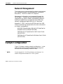
Network Management . . . . . . . . . . . . . . . . . . . . . . . . . . . .
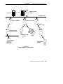
Sample Configuration . . . . . . . . . . . . . . . . . . . . . . . . . . . . . . . .
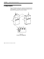
Components . . . . . . . . . . . . . . . . . . . . . . . . . . . . . . . . . . . . . . . . .
Accessories . . . . . . . . . . . . . . . . . . . . . . . . . . . . . . . . . . . . . . . . . .
Power Cord . . . . . . . . . . . . . . . . . . . . . . . . . . . . . . . . . . . . . .
Industrial Locking Mounting Bracket . . . . . . . . . . . . . .
2-11
2-11
2-11
2-12
2-12
2-12
2-12
2-13
2-13
2-13
2-13
2-14
2-14
2-16
2-19
2-19
2-19
SECTION 3
Installation . . . . . . . . . . . . . . . . . . . . . . . . . . . . . . . . . . . . . . . . . .
3-1
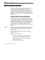
Checking the Default Configuration . . . . . . . . . . . . . . . . . . .
Preparing for the Installation . . . . . . . . . . . . . . . . . . . . . . . . .
Collecting the Equipment . . . . . . . . . . . . . . . . . . . . . . . . . . . .
Ethernet LAN Components . . . . . . . . . . . . . . . . . . . . . . .
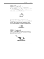
10BASE2 Components . . . . . . . . . . . . . . . . . . . . . . . .
10BASE-T Component . . . . . . . . . . . . . . . . . . . . . . . .
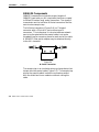
10BASE5 Components . . . . . . . . . . . . . . . . . . . . . . . .
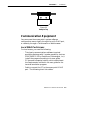
Communication Equipment . . . . . . . . . . . . . . . . . . . . . . .
Local DIAG Port Access . . . . . . . . . . . . . . . . . . . . . . .
Telnet . . . . . . . . . . . . . . . . . . . . . . . . . . . . . . . . . . . . . . .
Web Browser . . . . . . . . . . . . . . . . . . . . . . . . . . . . . . . . .
Network Management Platform . . . . . . . . . . . . . . . . . . .
Finding the Best Location . . . . . . . . . . . . . . . . . . . . . . . . . . . .
Site Survey . . . . . . . . . . . . . . . . . . . . . . . . . . . . . . . . . . . . . .
General Installation Guidelines . . . . . . . . . . . . . . . . . . .
Mounting the Access Point . . . . . . . . . . . . . . . . . . . . . . . . . . .
Horizontal (Tabletop) Mount . . . . . . . . . . . . . . . . . . . . . .
Vertical and Ceiling Mounts . . . . . . . . . . . . . . . . . . . . . . .
3-1
3-2
3-2
3-2
3-3
3-3
3-4
3-5
3-5
3-6
3-6
3-6
3-7
3-7
3-7
3-8
3-8
3-9
6710 Access Point User’s Guide
CONTENTS
Connecting to Ethernet . . . . . . . . . . . . . . . . . . . . . . . . . . . . . .
10BASE2 Ethernet . . . . . . . . . . . . . . . . . . . . . . . . . . . . . . .
End of Segment . . . . . . . . . . . . . . . . . . . . . . . . . . . . . .
Middle of Segment . . . . . . . . . . . . . . . . . . . . . . . . . . . .
10BASE5 Ethernet . . . . . . . . . . . . . . . . . . . . . . . . . . . . . . .
N-Series Transceiver . . . . . . . . . . . . . . . . . . . . . . . . . .
Vampire Tap . . . . . . . . . . . . . . . . . . . . . . . . . . . . . . . . .
10BASE-T Ethernet . . . . . . . . . . . . . . . . . . . . . . . . . . . . . .
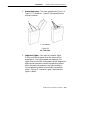
Installing PC Cards . . . . . . . . . . . . . . . . . . . . . . . . . . . . . . . . . .
WLIF . . . . . . . . . . . . . . . . . . . . . . . . . . . . . . . . . . . . . . . . . . .
900 MHz . . . . . . . . . . . . . . . . . . . . . . . . . . . . . . . . . . . . . . . .
S-UHF . . . . . . . . . . . . . . . . . . . . . . . . . . . . . . . . . . . . . . . . . .
Applying Power . . . . . . . . . . . . . . . . . . . . . . . . . . . . . . . . . . . . .
"
3-10
3-11
3-11
3-12
3-13
3-13
3-13
3-16
3-17
3-17
3-18
3-19
3-20
SECTION 4
Configuration . . . . . . . . . . . . . . . . . . . . . . . . . . . . . . . . . . . . . . .
4-1
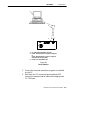
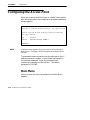
Creating a Local DIAG Port Session . . . . . . . . . . . . . . . . . . .
Accessing the Configuration Menus . . . . . . . . . . . . . . . .
Accessing the ROM Command Monitor . . . . . . . . . . . . .
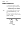
Creating a Telnet Session . . . . . . . . . . . . . . . . . . . . . . . . . . . . .
Default and Site Settings . . . . . . . . . . . . . . . . . . . . . . . . . . . . .
TCP/IP . . . . . . . . . . . . . . . . . . . . . . . . . . . . . . . . . . . . . . . . . .
Security . . . . . . . . . . . . . . . . . . . . . . . . . . . . . . . . . . . . . . . . .
Bridge . . . . . . . . . . . . . . . . . . . . . . . . . . . . . . . . . . . . . . . . . .
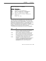
Configuring the Access Point . . . . . . . . . . . . . . . . . . . . . . . . .
Main Menu . . . . . . . . . . . . . . . . . . . . . . . . . . . . . . . . . . . . . .
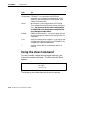
Using the View Command . . . . . . . . . . . . . . . . . . . . . . . .
TCP/IP Options . . . . . . . . . . . . . . . . . . . . . . . . . . . . . . . . . . . . . .
IP Address . . . . . . . . . . . . . . . . . . . . . . . . . . . . . . . . . . . . . .
IP Subnet Mask . . . . . . . . . . . . . . . . . . . . . . . . . . . . . . . . . .
IP Router . . . . . . . . . . . . . . . . . . . . . . . . . . . . . . . . . . . . . . . .
IP Frame Type . . . . . . . . . . . . . . . . . . . . . . . . . . . . . . . . . . .
DHCP . . . . . . . . . . . . . . . . . . . . . . . . . . . . . . . . . . . . . . . . . . .
DHCP Server Name . . . . . . . . . . . . . . . . . . . . . . . . . . . . . .
Bootp Operation . . . . . . . . . . . . . . . . . . . . . . . . . . . . . .
Networks With DHCP and Bootp Servers . . . . . . .
Handshaking . . . . . . . . . . . . . . . . . . . . . . . . . . . . . . . .
Infinite Leases . . . . . . . . . . . . . . . . . . . . . . . . . . . . . . .
Auto ARP Minutes . . . . . . . . . . . . . . . . . . . . . . . . . . . . . . .
4-2
4-4
4-5
4-6
4-7
4-7
4-8
4-8
4-12
4-12
4-14
4-16
4-16
4-17
4-18
4-19
4-19
4-20
4-21
4-21
4-21
4-21
4-22
6710 Access Point User’s Guide
iii
CONTENTS
"
Bridge Options . . . . . . . . . . . . . . . . . . . . . . . . . . . . . . . . . . . . . .
Serial Number . . . . . . . . . . . . . . . . . . . . . . . . . . . . . . . . . . .
Lan ID . . . . . . . . . . . . . . . . . . . . . . . . . . . . . . . . . . . . . . . . . .
[Root] . . . . . . . . . . . . . . . . . . . . . . . . . . . . . . . . . . . . . . . . . . .
Root Priority . . . . . . . . . . . . . . . . . . . . . . . . . . . . . . . . .
Super Root Candidates . . . . . . . . . . . . . . . . . . . .
Super Root Selection . . . . . . . . . . . . . . . . . . . . . .
Super Root Redundancy . . . . . . . . . . . . . . . . . . .
[Global Radio] . . . . . . . . . . . . . . . . . . . . . . . . . . . . . . . .
Set Globally . . . . . . . . . . . . . . . . . . . . . . . . . . . . . .
Value . . . . . . . . . . . . . . . . . . . . . . . . . . . . . . . . . . . .
[Global Flooding] . . . . . . . . . . . . . . . . . . . . . . . . . . . . .
Inbound . . . . . . . . . . . . . . . . . . . . . . . . . . . . . . . . . .
Outbound to Secondaries . . . . . . . . . . . . . . . . . .
Outbound to Stations . . . . . . . . . . . . . . . . . . . . . .
Flooding Level Checklist . . . . . . . . . . . . . . . . . . . . . .
S-UHF Flooding Level . . . . . . . . . . . . . . . . . . . . . . . .
Flood Register . . . . . . . . . . . . . . . . . . . . . . . . . . . . . . . .
ARP Server Mode . . . . . . . . . . . . . . . . . . . . . . . . . . . . . . . .
[Ports] . . . . . . . . . . . . . . . . . . . . . . . . . . . . . . . . . . . . . . . . . .
Name . . . . . . . . . . . . . . . . . . . . . . . . . . . . . . . . . . . . . . . .
MAC Address . . . . . . . . . . . . . . . . . . . . . . . . . . . . . . . .
Status . . . . . . . . . . . . . . . . . . . . . . . . . . . . . . . . . . . . . . .
Hello Period . . . . . . . . . . . . . . . . . . . . . . . . . . . . . . . . . .
Ethernet Options . . . . . . . . . . . . . . . . . . . . . . . . . . . . . . . . . . . .
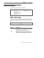
OWL Frame Type . . . . . . . . . . . . . . . . . . . . . . . . . . . . . . . .
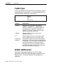
Cable Type . . . . . . . . . . . . . . . . . . . . . . . . . . . . . . . . . . . . . .
[Static Addresses] . . . . . . . . . . . . . . . . . . . . . . . . . . . . . . . .
[Normal RX Filter] . . . . . . . . . . . . . . . . . . . . . . . . . . . . . . .
[Frame Types] . . . . . . . . . . . . . . . . . . . . . . . . . . . . . . . .
[SubTypes 1] . . . . . . . . . . . . . . . . . . . . . . . . . . . . . . . . .
User-Defined Subtypes in [SubTypes 1]
and [SubTypes 2] . . . . . . . . . . . . . . . . . . . . . . . . .
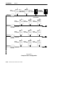
Filtering Examples . . . . . . . . . . . . . . . . . . . . . . . . . . .
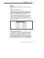
Example 1 . . . . . . . . . . . . . . . . . . . . . . . . . . . . . . . .
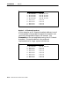
Example 2 . . . . . . . . . . . . . . . . . . . . . . . . . . . . . . . .
iv
6710 Access Point User’s Guide
4-23
4-23
4-23
4-24
4-24
4-24
4-25
4-25
4-25
4-27
4-27
4-28
4-28
4-29
4-30
4-31
4-36
4-36
4-36
4-38
4-39
4-39
4-40
4-40
4-41
4-41
4-42
4-42
4-43
4-44
4-46
4-46
4-48
4-49
4-50
CONTENTS
[Advanced RX Filter] . . . . . . . . . . . . . . . . . . . . . . . . . . . . .
[Expressions] . . . . . . . . . . . . . . . . . . . . . . . . . . . . . . . . .
ExprSeq . . . . . . . . . . . . . . . . . . . . . . . . . . . . . . . . . .
Offset . . . . . . . . . . . . . . . . . . . . . . . . . . . . . . . . . . . .
Mask . . . . . . . . . . . . . . . . . . . . . . . . . . . . . . . . . . . .
Op . . . . . . . . . . . . . . . . . . . . . . . . . . . . . . . . . . . . . . .
Value Id . . . . . . . . . . . . . . . . . . . . . . . . . . . . . . . . . .
Action . . . . . . . . . . . . . . . . . . . . . . . . . . . . . . . . . . .
[Values] . . . . . . . . . . . . . . . . . . . . . . . . . . . . . . . . . . . . . .
[Bridging] . . . . . . . . . . . . . . . . . . . . . . . . . . . . . . . . . . . . . . .
Bridge Priority . . . . . . . . . . . . . . . . . . . . . . . . . . . . . . .
Designated Bridge Candidates . . . . . . . . . . . . .
Designated Bridge Selection . . . . . . . . . . . . . . .
Summary . . . . . . . . . . . . . . . . . . . . . . . . . . . . . . . .
Status . . . . . . . . . . . . . . . . . . . . . . . . . . . . . . . . . . . . . . .
Flood Register . . . . . . . . . . . . . . . . . . . . . . . . . . . . . . . .
WLIF Options . . . . . . . . . . . . . . . . . . . . . . . . . . . . . . . . . . . . . . .
Security Id . . . . . . . . . . . . . . . . . . . . . . . . . . . . . . . . . . . . . .
Node Type . . . . . . . . . . . . . . . . . . . . . . . . . . . . . . . . . . . . . . .
[Master Parms] . . . . . . . . . . . . . . . . . . . . . . . . . . . . . . . . . .
Channel and Subchannel . . . . . . . . . . . . . . . . . . . . . .
Network With 15 or Fewer Access Points . . . .
Network With 16 or More Access Points . . . . .
Wireless Hops . . . . . . . . . . . . . . . . . . . . . . . . . . . . . . . .
[Slave Parms] . . . . . . . . . . . . . . . . . . . . . . . . . . . . . . . . . . . .
MAC Config . . . . . . . . . . . . . . . . . . . . . . . . . . . . . . . . . . . . .
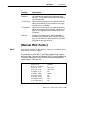
[Manual MAC Parms] . . . . . . . . . . . . . . . . . . . . . . . . . . . .
Hop Period . . . . . . . . . . . . . . . . . . . . . . . . . . . . . . . . . . .
Beacon Frequency . . . . . . . . . . . . . . . . . . . . . . . . . . . .
Deferral Slot and Fairness Slot . . . . . . . . . . . . . . . .
Fragment Size . . . . . . . . . . . . . . . . . . . . . . . . . . . . . . .
Transmit Mode . . . . . . . . . . . . . . . . . . . . . . . . . . . . . . .
Norm Ack Retry . . . . . . . . . . . . . . . . . . . . . . . . . . . . . .
Frag Ack Retry . . . . . . . . . . . . . . . . . . . . . . . . . . . . . . .
Norm QFSK Retry . . . . . . . . . . . . . . . . . . . . . . . . . . . .
Frag QFSK Retry . . . . . . . . . . . . . . . . . . . . . . . . . . . . .
900 MHz Options . . . . . . . . . . . . . . . . . . . . . . . . . . . . . . . . . . . .
File Name . . . . . . . . . . . . . . . . . . . . . . . . . . . . . . . . . . . . . . .
Mode--Channel . . . . . . . . . . . . . . . . . . . . . . . . . . . . . . . . . . .
"
4-52
4-52
4-53
4-54
4-54
4-54
4-55
4-55
4-56
4-57
4-57
4-57
4-58
4-58
4-58
4-59
4-60
4-60
4-61
4-62
4-62
4-63
4-63
4-65
4-66
4-68
4-69
4-70
4-70
4-70
4-71
4-72
4-72
4-73
4-73
4-73
4-74
4-74
4-74
6710 Access Point User’s Guide
v
CONTENTS
vi
"
S-UHF Options . . . . . . . . . . . . . . . . . . . . . . . . . . . . . . . . . . . . . .
File Name . . . . . . . . . . . . . . . . . . . . . . . . . . . . . . . . . . . . . . .
Call Sign . . . . . . . . . . . . . . . . . . . . . . . . . . . . . . . . . . . . . . . .
Frequency . . . . . . . . . . . . . . . . . . . . . . . . . . . . . . . . . . . . . . .
Master Mode . . . . . . . . . . . . . . . . . . . . . . . . . . . . . . . . . . . .
Attach Priority . . . . . . . . . . . . . . . . . . . . . . . . . . . . . . . . . . .
OWL/IP Options . . . . . . . . . . . . . . . . . . . . . . . . . . . . . . . . . . . . .
Overview . . . . . . . . . . . . . . . . . . . . . . . . . . . . . . . . . . . . . . . .
OWL/IP Menu . . . . . . . . . . . . . . . . . . . . . . . . . . . . . . . . . . .
Mode . . . . . . . . . . . . . . . . . . . . . . . . . . . . . . . . . . . . . . . .
[IP Addresses] . . . . . . . . . . . . . . . . . . . . . . . . . . . . . . . .
Type . . . . . . . . . . . . . . . . . . . . . . . . . . . . . . . . . . . . .
Address . . . . . . . . . . . . . . . . . . . . . . . . . . . . . . . . . .
[TX Filter] . . . . . . . . . . . . . . . . . . . . . . . . . . . . . . . . . . .
Security Options . . . . . . . . . . . . . . . . . . . . . . . . . . . . . . . . . . . . .
Password . . . . . . . . . . . . . . . . . . . . . . . . . . . . . . . . . . . .
Service Password . . . . . . . . . . . . . . . . . . . . . . . . . . . . .
Advanced Password . . . . . . . . . . . . . . . . . . . . . . . . . . .
Combining Radio Options . . . . . . . . . . . . . . . . . . . . . . . . . . . .
Same LAN ID . . . . . . . . . . . . . . . . . . . . . . . . . . . . . . . . . . . .
Different LAN IDs . . . . . . . . . . . . . . . . . . . . . . . . . . . . . . .
Creating a Web Browser Session . . . . . . . . . . . . . . . . . . . . . .
Configuration Guidelines . . . . . . . . . . . . . . . . . . . . . . . . . . . . .
Planning Your Installation . . . . . . . . . . . . . . . . . . . . . . . .
Using the Configuration Guide . . . . . . . . . . . . . . . . . . . .
4-76
4-76
4-76
4-77
4-77
4-78
4-79
4-79
4-82
4-82
4-83
4-83
4-84
4-84
4-86
4-86
4-86
4-87
4-87
4-87
4-88
4-88
4-92
4-92
4-92
SECTION 5
Software Download . . . . . . . . . . . . . . . . . . . . . . . . . . . . . . . . . .
5-1
File System Structure . . . . . . . . . . . . . . . . . . . . . . . . . . . . . . . .
Boot Segments 1 and 2 . . . . . . . . . . . . . . . . . . . . . . . . . . .
Data Segments 3 and 4 . . . . . . . . . . . . . . . . . . . . . . . . . . .
Active and Inactive Segments . . . . . . . . . . . . . . . . . . . . .
RAM Segment . . . . . . . . . . . . . . . . . . . . . . . . . . . . . . . . . . .
Segment Names . . . . . . . . . . . . . . . . . . . . . . . . . . . . . . . . . . . . .
File Names . . . . . . . . . . . . . . . . . . . . . . . . . . . . . . . . . . . . . . . . . .
Downloading Programs . . . . . . . . . . . . . . . . . . . . . . . . . . . . . .
File Menu Commands . . . . . . . . . . . . . . . . . . . . . . . . . . . . . . . .
Fb Command . . . . . . . . . . . . . . . . . . . . . . . . . . . . . . . . . . . . . . . .
Fd Command . . . . . . . . . . . . . . . . . . . . . . . . . . . . . . . . . . . . . . . .
Fdel Command . . . . . . . . . . . . . . . . . . . . . . . . . . . . . . . . . . . . . .
5-1
5-1
5-1
5-2
5-3
5-3
5-4
5-4
5-4
5-5
5-6
5-7
6710 Access Point User’s Guide
CONTENTS
Fe Command . . . . . . . . . . . . . . . . . . . . . . . . . . . . . . . . . . . . . . . .
TFTP Command . . . . . . . . . . . . . . . . . . . . . . . . . . . . . . . . . . . . .
TFTP Server . . . . . . . . . . . . . . . . . . . . . . . . . . . . . . . . . . . . .
Server Start . . . . . . . . . . . . . . . . . . . . . . . . . . . . . . . . . .
Server Stop . . . . . . . . . . . . . . . . . . . . . . . . . . . . . . . . . .
Server Log . . . . . . . . . . . . . . . . . . . . . . . . . . . . . . . . . . .
TFTP Client Commands . . . . . . . . . . . . . . . . . . . . . . . . . .
Get . . . . . . . . . . . . . . . . . . . . . . . . . . . . . . . . . . . . . . . . . .
Put . . . . . . . . . . . . . . . . . . . . . . . . . . . . . . . . . . . . . . . . . .
Script Command . . . . . . . . . . . . . . . . . . . . . . . . . . . . . . . . . . . . .
Creating Script Files . . . . . . . . . . . . . . . . . . . . . . . . . . . . .
Sample Script File . . . . . . . . . . . . . . . . . . . . . . . . . . . . . . .
Script File Command Summary . . . . . . . . . . . . . . . . . . .
TFTP Client Command Retry . . . . . . . . . . . . . . . . . . . . .
Reboot Command . . . . . . . . . . . . . . . . . . . . . . . . . . . . . . . .
SDVars Command . . . . . . . . . . . . . . . . . . . . . . . . . . . . . . . . . . .
ServerIpAddress . . . . . . . . . . . . . . . . . . . . . . . . . . . . . . . . .
ScriptFilename . . . . . . . . . . . . . . . . . . . . . . . . . . . . . . . . . .
StartTime . . . . . . . . . . . . . . . . . . . . . . . . . . . . . . . . . . . . . . .
Status . . . . . . . . . . . . . . . . . . . . . . . . . . . . . . . . . . . . . . . . . . .
CheckPoint . . . . . . . . . . . . . . . . . . . . . . . . . . . . . . . . . . . . . .
Terminate . . . . . . . . . . . . . . . . . . . . . . . . . . . . . . . . . . . . . . .
SetActivePointers . . . . . . . . . . . . . . . . . . . . . . . . . . . . . . . .
NextPowerUpTime . . . . . . . . . . . . . . . . . . . . . . . . . . . . . . .
ROM Command Monitor . . . . . . . . . . . . . . . . . . . . . . . . . . . . .
Starting the Command Monitor . . . . . . . . . . . . . . . . . . .
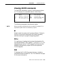
Viewing ROM Commands . . . . . . . . . . . . . . . . . . . . . . . . .
B ...............................................
FX s . . . . . . . . . . . . . . . . . . . . . . . . . . . . . . . . . . . . . . . . . . . .
FD . . . . . . . . . . . . . . . . . . . . . . . . . . . . . . . . . . . . . . . . . . . . . .
FR . . . . . . . . . . . . . . . . . . . . . . . . . . . . . . . . . . . . . . . . . . . . . .
NPWD . . . . . . . . . . . . . . . . . . . . . . . . . . . . . . . . . . . . . . . . . .
SR z . . . . . . . . . . . . . . . . . . . . . . . . . . . . . . . . . . . . . . . . . . . .
PWD . . . . . . . . . . . . . . . . . . . . . . . . . . . . . . . . . . . . . . . . . . . .
FD . . . . . . . . . . . . . . . . . . . . . . . . . . . . . . . . . . . . . . . . . .
FE <s|all> . . . . . . . . . . . . . . . . . . . . . . . . . . . . . . . . . . .
FI . . . . . . . . . . . . . . . . . . . . . . . . . . . . . . . . . . . . . . . . . . .
FS s n . . . . . . . . . . . . . . . . . . . . . . . . . . . . . . . . . . . . . . .
FB s . . . . . . . . . . . . . . . . . . . . . . . . . . . . . . . . . . . . . . . . .
FFR f . . . . . . . . . . . . . . . . . . . . . . . . . . . . . . . . . . . . . . . .
FPC f s . . . . . . . . . . . . . . . . . . . . . . . . . . . . . . . . . . . . . .
6710 Access Point User’s Guide
"
5-8
5-8
5-9
5-10
5-10
5-10
5-10
5-11
5-12
5-12
5-13
5-14
5-15
5-16
5-16
5-17
5-18
5-18
5-18
5-19
5-19
5-20
5-21
5-21
5-22
5-22
5-23
5-23
5-23
5-23
5-24
5-24
5-24
5-25
5-25
5-25
5-26
5-26
5-26
5-26
5-26
vii
CONTENTS
"
FPD . . . . . . . . . . . . . . . . . . . . . . . . . . . . . . . . . . . . . . . . .
FPE . . . . . . . . . . . . . . . . . . . . . . . . . . . . . . . . . . . . . . . . .
FPX . . . . . . . . . . . . . . . . . . . . . . . . . . . . . . . . . . . . . . . . .
PN . . . . . . . . . . . . . . . . . . . . . . . . . . . . . . . . . . . . . . . . .
PQ . . . . . . . . . . . . . . . . . . . . . . . . . . . . . . . . . . . . . . . . . .
MI String . . . . . . . . . . . . . . . . . . . . . . . . . . . . . . . . . . . .
RMI . . . . . . . . . . . . . . . . . . . . . . . . . . . . . . . . . . . . . . . . .
X ............................................
Exiting the ROM Command Monitor . . . . . . . . . . . . . . .
Software Download Example . . . . . . . . . . . . . . . . . . . . . . . . .
Upgrading Through DIAG Port . . . . . . . . . . . . . . . . . . .
Starting the TFTP Server . . . . . . . . . . . . . . . . . . . . . . . . .
Upgrading TFTP Clients . . . . . . . . . . . . . . . . . . . . . . . . . .
5-26
5-27
5-27
5-27
5-27
5-28
5-28
5-28
5-29
5-29
5-29
5-31
5-31
SECTION 6
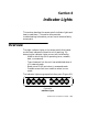
Indicator Lights . . . . . . . . . . . . . . . . . . . . . . . . . . . . . . . . . . . . .
6-1
Overview . . . . . . . . . . . . . . . . . . . . . . . . . . . . . . . . . . . . . . . . . . .
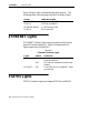
ETHERNET Lights . . . . . . . . . . . . . . . . . . . . . . . . . . . . . . . . . .
STATUS Lights . . . . . . . . . . . . . . . . . . . . . . . . . . . . . . . . . . . . . .
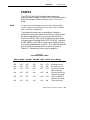
STATUS . . . . . . . . . . . . . . . . . . . . . . . . . . . . . . . . . . . . . . . . .
MODE . . . . . . . . . . . . . . . . . . . . . . . . . . . . . . . . . . . . . . . . . .
NETWORK MODE Lights . . . . . . . . . . . . . . . . . . . . . . . . . . . .
PCMCIA Lights . . . . . . . . . . . . . . . . . . . . . . . . . . . . . . . . . . . . .
Power-Up Sequence . . . . . . . . . . . . . . . . . . . . . . . . . . . . . . . . . .
6-1
6-2
6-2
6-3
6-4
6-5
6-6
6-7
APPENDIX A
viii
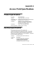
Access Point Specifications . . . . . . . . . . . . . . . . . . . . . . . . .
A-1
Product Specifications . . . . . . . . . . . . . . . . . . . . . . . . . . . . . . . .
Electrical Specifications . . . . . . . . . . . . . . . . . . . . . . . . . . . . . .
Environmental Specifications . . . . . . . . . . . . . . . . . . . . . . . . .
Physical Characteristics . . . . . . . . . . . . . . . . . . . . . . . . . . . . . .
A-1
A-1
A-2
A-2
6710 Access Point User’s Guide
CONTENTS
"
APPENDIX B
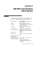
WLIF Specifications and Antennas . . . . . . . . . . . . . . . . . . .
B-1
RM180 . . . . . . . . . . . . . . . . . . . . . . . . . . . . . . . . . . . . . . . . . . . . . .
Radio Operation . . . . . . . . . . . . . . . . . . . . . . . . . . . . . . . . .
Part Numbers . . . . . . . . . . . . . . . . . . . . . . . . . . . . . . . . . . .
Antenna Regulations . . . . . . . . . . . . . . . . . . . . . . . . . . . . . . . . .
Whip Antenna . . . . . . . . . . . . . . . . . . . . . . . . . . . . . . . . . . . . . . .
Remote Antenna Kits . . . . . . . . . . . . . . . . . . . . . . . . . . . . . . . .
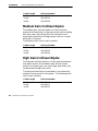
Medium Gain Patch . . . . . . . . . . . . . . . . . . . . . . . . . . . . . .
Medium Gain Collinear Dipole . . . . . . . . . . . . . . . . . . . .
High Gain Collinear Dipole . . . . . . . . . . . . . . . . . . . . . . .
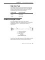
High Gain Yagi . . . . . . . . . . . . . . . . . . . . . . . . . . . . . . . . . .
Antenna Adapter Cable . . . . . . . . . . . . . . . . . . . . . . . . . . . . . .
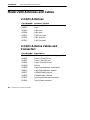
Model 2100 Antennas and Cables . . . . . . . . . . . . . . . . . . . . .
2.4 GHz Antennas . . . . . . . . . . . . . . . . . . . . . . . . . . . . . . . .
2.4 GHz Antenna Cables and Connectors . . . . . . . . . . .
B-1
B-2
B-2
B-3
B-3
B-3
B-3
B-4
B-4
B-5
B-5
B-6
B-6
B-6
APPENDIX C
900 MHz Specifications and Antennas . . . . . . . . . . . . . . . .
C-1
RM160 . . . . . . . . . . . . . . . . . . . . . . . . . . . . . . . . . . . . . . . . . . . . . .
Radio Operation . . . . . . . . . . . . . . . . . . . . . . . . . . . . . . . . .
Part Numbers . . . . . . . . . . . . . . . . . . . . . . . . . . . . . . . . . . .
Antenna Regulations . . . . . . . . . . . . . . . . . . . . . . . . . . . . . . . . .
Whip Antenna . . . . . . . . . . . . . . . . . . . . . . . . . . . . . . . . . . . . . . .
Remote Antenna Kits . . . . . . . . . . . . . . . . . . . . . . . . . . . . . . . .
C-1
C-2
C-2
C-2
C-2
C-3
APPENDIX D
S-UHF Specifications and Antennas . . . . . . . . . . . . . . . . . .
D-1
RM111 . . . . . . . . . . . . . . . . . . . . . . . . . . . . . . . . . . . . . . . . . . . . . .
Radio Operation . . . . . . . . . . . . . . . . . . . . . . . . . . . . . . . . .
Part Numbers . . . . . . . . . . . . . . . . . . . . . . . . . . . . . . . . . . .
Wireless Hops . . . . . . . . . . . . . . . . . . . . . . . . . . . . . . . . . . .
Antenna Connector . . . . . . . . . . . . . . . . . . . . . . . . . . . . . . . . . .
Whip Antennas . . . . . . . . . . . . . . . . . . . . . . . . . . . . . . . . . . . . . .
Site License . . . . . . . . . . . . . . . . . . . . . . . . . . . . . . . . . . . . . . . . .
Technology . . . . . . . . . . . . . . . . . . . . . . . . . . . . . . . . . . . . . . . . . .
Transaction Rates . . . . . . . . . . . . . . . . . . . . . . . . . . . . . . . . . . .
D-1
D-2
D-2
D-3
D-3
D-3
D-4
D-4
D-4
6710 Access Point User’s Guide
ix
CONTENTS
"
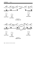
Installation Guidelines . . . . . . . . . . . . . . . . . . . . . . . . . . . . . . .
Predicting Coverage . . . . . . . . . . . . . . . . . . . . . . . . . . . . . .
Installing a Single Access Point . . . . . . . . . . . . . . . . . . .
Installing Multiple Access Points . . . . . . . . . . . . . . . . . .
Extending Coverage . . . . . . . . . . . . . . . . . . . . . . . . . .
Reusing the Frequency . . . . . . . . . . . . . . . . . . . . . . . .
Increasing System Throughput . . . . . . . . . . . . . . . .
Option 1 . . . . . . . . . . . . . . . . . . . . . . . . . . . . . . . . .
Option 2 . . . . . . . . . . . . . . . . . . . . . . . . . . . . . . . . .
Frequency and Separation Guidelines . . . . . . . . . .
D-5
D-5
D-6
D-6
D-6
D-7
D-8
D-9
D-9
D-10
APPENDIX E
x
OWL/IP . . . . . . . . . . . . . . . . . . . . . . . . . . . . . . . . . . . . . . . . . . . . .
E-1
Introduction . . . . . . . . . . . . . . . . . . . . . . . . . . . . . . . . . . . . . . . . .
OWL/IP Restrictions . . . . . . . . . . . . . . . . . . . . . . . . . . . . . . . . .
Addressing Limitations . . . . . . . . . . . . . . . . . . . . . . . . . . .
Installation Limitations . . . . . . . . . . . . . . . . . . . . . . . . . . .
OWL/IP Safeguards . . . . . . . . . . . . . . . . . . . . . . . . . . . . . . . . . .
Default Settings . . . . . . . . . . . . . . . . . . . . . . . . . . . . . . . . .
Addressing Limitations and Flooding Restrictions . . .
Permanent Filters . . . . . . . . . . . . . . . . . . . . . . . . . . . . . . . .
Default Filter Settings . . . . . . . . . . . . . . . . . . . . . . . . . . . .
Subnet Filtering . . . . . . . . . . . . . . . . . . . . . . . . . . . . . . . . .
Password Security . . . . . . . . . . . . . . . . . . . . . . . . . . . . . . .
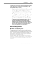
Operation . . . . . . . . . . . . . . . . . . . . . . . . . . . . . . . . . . . . . . .
Tunnel Origination . . . . . . . . . . . . . . . . . . . . . . . . . . . . . . .
Building the Spanning Tree . . . . . . . . . . . . . . . . . . .
Establishing and Maintaining Tunnels . . . . . . . . .
Redundancy . . . . . . . . . . . . . . . . . . . . . . . . . . . . . . . . .
Frame Forwarding . . . . . . . . . . . . . . . . . . . . . . . . . . . . . . .
Outbound . . . . . . . . . . . . . . . . . . . . . . . . . . . . . . . . . . . .
Inbound . . . . . . . . . . . . . . . . . . . . . . . . . . . . . . . . . . . . .
Station Mobility . . . . . . . . . . . . . . . . . . . . . . . . . . . . . . . . . .
Mobile IP Comparison . . . . . . . . . . . . . . . . . . . . . . . . . . . . . . . .
E-1
E-2
E-2
E-2
E-3
E-3
E-4
E-4
E-6
E-6
E-7
E-7
E-9
E-9
E-10
E-10
E-11
E-11
E-11
E-12
E-12
6710 Access Point User’s Guide
CONTENTS
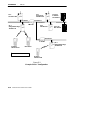
OWL/IP Configuration Examples . . . . . . . . . . . . . . . . . . . . .
Example 1: Class C IP Addresses . . . . . . . . . . . . . . . . .
Step 1 . . . . . . . . . . . . . . . . . . . . . . . . . . . . . . . . . . . . . . .
Step 2 . . . . . . . . . . . . . . . . . . . . . . . . . . . . . . . . . . . . . . .
Step 3 . . . . . . . . . . . . . . . . . . . . . . . . . . . . . . . . . . . . . . .
Option A: Unicast Addressing . . . . . . . . . . . . .
Option B: Directed Broadcast . . . . . . . . . . . . . .
Step 4: Set TX Filters . . . . . . . . . . . . . . . . . . . . . . . .
Example 2: Class B IP Address Using Subnetting . .
Step 1 . . . . . . . . . . . . . . . . . . . . . . . . . . . . . . . . . . . . . . .
Step 2 . . . . . . . . . . . . . . . . . . . . . . . . . . . . . . . . . . . . . . .
Step 3 . . . . . . . . . . . . . . . . . . . . . . . . . . . . . . . . . . . . . . .
Option A: Unicast Addressing . . . . . . . . . . . . .
Option B: Directed Broadcast . . . . . . . . . . . . . .
Option C: All Subnets Broadcast . . . . . . . . . . .
Step 4 . . . . . . . . . . . . . . . . . . . . . . . . . . . . . . . . . . . . . . .
"
E-13
E-13
E-15
E-15
E-15
E-16
E-16
E-17
E-19
E-19
E-19
E-21
E-21
E-21
E-22
E-23
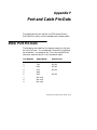
APPENDIX F
Port and Cable Pin-Outs . . . . . . . . . . . . . . . . . . . . . . . . . . . . .
F-1
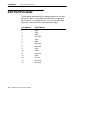
DIAG Port Pin-Outs . . . . . . . . . . . . . . . . . . . . . . . . . . . . . . . . .
AUI Port Pin-Outs . . . . . . . . . . . . . . . . . . . . . . . . . . . . . . . . . . .
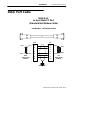
DIAG Port Cable . . . . . . . . . . . . . . . . . . . . . . . . . . . . . . . . . . . .
F-1
F-2
F-3
APPENDIX G
MIB . . . . . . . . . . . . . . . . . . . . . . . . . . . . . . . . . . . . . . . . . . . . . . . .
G-1
Product Contents . . . . . . . . . . . . . . . . . . . . . . . . . . . . . . . . . . . .
About This Product . . . . . . . . . . . . . . . . . . . . . . . . . . . . . . . . . .
Getting Started . . . . . . . . . . . . . . . . . . . . . . . . . . . . . . . . . . . . . .
MIB-II Information . . . . . . . . . . . . . . . . . . . . . . . . . . . . . . . . . .
6710 Access Point MIB Information . . . . . . . . . . . . . . . . . . .
Access to Management Information . . . . . . . . . . . . . . . . . . .
MIB-II Notes . . . . . . . . . . . . . . . . . . . . . . . . . . . . . . . . . . . . . . . .
MIB Directory . . . . . . . . . . . . . . . . . . . . . . . . . . . . . . . . . . . . . . .
G-1
G-1
G-2
G-2
G-3
G-4
G-6
G-6
6710 Access Point User’s Guide
xi
CONTENTS
"
MIB Outline . . . . . . . . . . . . . . . . . . . . . . . . . . . . . . . . . . . . . . . .
Product OIDs . . . . . . . . . . . . . . . . . . . . . . . . . . . . . . . . . . . .
System Information . . . . . . . . . . . . . . . . . . . . . . . . . . . . . .
Interface Information . . . . . . . . . . . . . . . . . . . . . . . . . . . . .
SNMP Version 1 Configuration Group . . . . . . . . . . . . .
Bridging Parameters . . . . . . . . . . . . . . . . . . . . . . . . . . . . .
Control Groups . . . . . . . . . . . . . . . . . . . . . . . . . . . . . . . . . .
MIB Definitions . . . . . . . . . . . . . . . . . . . . . . . . . . . . . . . . . . . . .
G-8
G-8
G-9
G-12
G-17
G-18
G-22
G-23
GLOSSARY . . . . . . . . . . . . . . . . . . . . . . . . . . . . . . . . . . . . . Glossary-1
INDEX . . . . . . . . . . . . . . . . . . . . . . . . . . . . . . . . . . . . . . . . . .
FIGURES
Figure 2-1
Figure 2-2
Figure 2-3
Figure 2-4
Figure 2-5
xii
Index-1
6710 Access Points . . . . . . . . . . . . . . . . . . . . . . . .
6710 Access Point Functions . . . . . . . . . . . . . .
Sample Network Configuration . . . . . . . . . . . .
Access Point Components . . . . . . . . . . . . . . . . . .
PC Card Slots . . . . . . . . . . . . . . . . . . . . . . . . . . . .
2-1
2-2
2-15
2-16
2-17
Figure 3-1 T-Connector . . . . . . . . . . . . . . . . . . . . . . . . . . . . . .
Figure 3-2 Cable Terminator . . . . . . . . . . . . . . . . . . . . . . . . .
Figure 3-3 Cable With RJ45 Plugs . . . . . . . . . . . . . . . . . . . .
Figure 3-4 N-Series Transceiver . . . . . . . . . . . . . . . . . . . . . .
Figure 3-5 Vampire Tap . . . . . . . . . . . . . . . . . . . . . . . . . . . . . .
Figure 3-6 Mounting Bracket . . . . . . . . . . . . . . . . . . . . . . . .
Figure 3-7 End of 10BASE2 Segment . . . . . . . . . . . . . . . . .
Figure 3-8 Middle of 10BASE2 Segment . . . . . . . . . . . . . . .
Figure 3-9 N-Series Transceiver . . . . . . . . . . . . . . . . . . . . . .
Figure 3-10 Vampire Tap . . . . . . . . . . . . . . . . . . . . . . . . . . . . .
Figure 3-11 10BASE-T . . . . . . . . . . . . . . . . . . . . . . . . . . . . . . .
Figure 3-12 WLIF PC Card Assembly . . . . . . . . . . . . . . . . .
Figure 3-13 900 MHz PC Card Assembly . . . . . . . . . . . . . .
Figure 3-14 S-UHF PC Card Assembly . . . . . . . . . . . . . . . .
Figure 3-15 AC Power Input Connection . . . . . . . . . . . . . .
3-3
3-3
3-3
3-4
3-5
3-9
3-11
3-12
3-14
3-15
3-16
3-17
3-18
3-19
3-21
6710 Access Point User’s Guide
CONTENTS
"
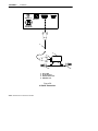
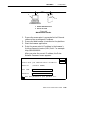
Figure 4-1 Local Session . . . . . . . . . . . . . . . . . . . . . . . . . . . . .
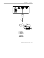
Figure 4-2 Telnet Session . . . . . . . . . . . . . . . . . . . . . . . . . . . .
Figure 4-3 Access Points Servicing IP Wireless
Stations . . . . . . . . . . . . . . . . . . . . . . . . . . . . . . . . . . . . . . . . .
Figure 4-4 Wireless Hopping Through WLIF Radios . . . .
Figure 4-5 OWL/IP Overview . . . . . . . . . . . . . . . . . . . . . . . .
Figure 4-6 Web Browser Session . . . . . . . . . . . . . . . . . . . . . .
4-49
4-65
4-80
4-89
Figure 6-1 Indicator Lights . . . . . . . . . . . . . . . . . . . . . . . . . .
6-1
Figure B-1 Antenna Adapter Cable . . . . . . . . . . . . . . . . . . .
B-5
Figure D-1 Extending Coverage . . . . . . . . . . . . . . . . . . . . . .
Figure D-2 Frequency Reuse . . . . . . . . . . . . . . . . . . . . . . . . .
Figure D-3 Increased System Throughput . . . . . . . . . . . . .
D-7
D-8
D-10
Figure E-1
Figure E-2
Figure E-3
Figure E-4
E-8
E-8
E-14
E-20
Secondary LAN . . . . . . . . . . . . . . . . . . . . . . . . . .
OWL/IP Tunnel . . . . . . . . . . . . . . . . . . . . . . . . . .
Example Class C Configuration . . . . . . . . . . . .
Example Class B Configuration . . . . . . . . . . . .
TABLES
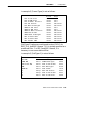
Table 4-1 Configuration Guide
Table 6-1
Table 6-2
Table 6-3
Table 6-4
Table 6-5
Table 6-6
......................
4-92
ETHERNET Indicator Lights . . . . . . . . . . . . . . .
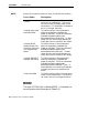
Error Mode Status Codes . . . . . . . . . . . . . . . . . . .
MODE Indicator Light . . . . . . . . . . . . . . . . . . . . .
NETWORK MODE Indicator Lights . . . . . . . . .
PCMCIA Indicator Lights . . . . . . . . . . . . . . . . . . .
DIAG Port Baud Rates, ROM Mode . . . . . . . . . .
6-2
6-3
6-5
6-5
6-6
6-6
Table D-1 Coverage Prediction
......................
D-5
....................
E-13
MIB-II Information . . . . . . . . . . . . . . . . . . . . . . . .
MIB Information . . . . . . . . . . . . . . . . . . . . . . . . . .
MIB Directory . . . . . . . . . . . . . . . . . . . . . . . . . . . . .
products GROUP . . . . . . . . . . . . . . . . . . . . . . . . .
hw GROUP . . . . . . . . . . . . . . . . . . . . . . . . . . . . . . .
fsinfo GROUP . . . . . . . . . . . . . . . . . . . . . . . . . . . . .
G-3
G-4
G-7
G-8
G-9
G-10
Table E-1 Mobile IP Comparison
Table G-1
Table G-2
Table G-3
Table G-4
Table G-5
Table G-6
4-3
4-6
6710 Access Point User’s Guide
xiii
CONTENTS
"
Table G-7 segment GROUP . . . . . . . . . . . . . . . . . . . . . . . . . .
Table G-8 dir GROUP . . . . . . . . . . . . . . . . . . . . . . . . . . . . . . .
Table G-9 criticalErrors GROUP . . . . . . . . . . . . . . . . . . . . . .
Table G-10 nifx GROUP . . . . . . . . . . . . . . . . . . . . . . . . . . . . .
Table G-11 portState GROUP . . . . . . . . . . . . . . . . . . . . . . . .
Table G-12 portStats GROUP . . . . . . . . . . . . . . . . . . . . . . . .
Table G-13 ptxq GROUP . . . . . . . . . . . . . . . . . . . . . . . . . . . . .
Table G-14 pmsg GROUP . . . . . . . . . . . . . . . . . . . . . . . . . . . .
Table G-15 community TABLE . . . . . . . . . . . . . . . . . . . . . . .
Table G-16 trapTarget TABLE . . . . . . . . . . . . . . . . . . . . . . . .
Table G-17 rt GROUP . . . . . . . . . . . . . . . . . . . . . . . . . . . . . . .
Table G-18 brg GROUP . . . . . . . . . . . . . . . . . . . . . . . . . . . . .
Table G-19 addr GROUP . . . . . . . . . . . . . . . . . . . . . . . . . . . .
Table G-20 brgState GROUP . . . . . . . . . . . . . . . . . . . . . . . . .
Table G-21 bridgeStats GROUP . . . . . . . . . . . . . . . . . . . . . .
Table G-22 powerUp GROUP . . . . . . . . . . . . . . . . . . . . . . . . .
Table G-23 softwareDownLoad GROUP . . . . . . . . . . . . . . .
xiv
6710 Access Point User’s Guide
G-10
G-11
G-11
G-12
G-13
G-14
G-15
G-16
G-17
G-17
G-18
G-19
G-20
G-20
G-22
G-23
G-23
Section 1
Preface
"
"
"
"
"
"
"
"
"
"
"
"
"
"
"
"
"
"
"
"
"
"
"
"
"
"
"
"
Purpose of This Guide
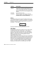
This user’s guide describes the installation, setup, and
maintenance of the 6710 Access Point. This guide covers
access point FLASH version 1.27 or greater and ROM
version 1.12 or greater.
Norand Corporation is now part of Intermec Technologies
Corporation. As part of our continuing efforts to offer the
broadest range of system solutions in the industry, the 6710
Access Point and other open wireless local area network
(LAN) components have been merged into the INTERMECR
Integrated Network Communications Architecture (INCA).
Where appropriate, we have continued to use the Norand
name in references to the open wireless LAN to maintain
continuity with existing product in the field.
Organization
This Preface describes the intended audience for this guide,
lists related publications, and tells how to contact the
Customer Response Center. Other sections do the
following:
Section 2,
“Features and
Functional
Overview”
Describes the access point and how
it operates on the open wireless
LAN. It also describes access point
components.
6710 Access Point User’s Guide
1-1
SECTION 1
"
Preface
Section 3,
“Installation”
Helps you prepare your site before
you install the access point, and
shows how to connect the access
point to 10BASE-T, 10BASE2, and
10BASE5 Ethernet.
Section 4,
“Configuration”
Describes how to create a
communications session with the
access point, access FLASH and
ROM, and set up the access point
through its configuration menus.
Section 5,
Describes file system methodology
“Software Download” and the functional characteristics
of the software download process.
Section 6,
“Indicator Lights”
Describes the access point’s
indicator lights and contains
troubleshooting tips.
Appendixes contain supplemental information:
Appendix A
Lists mechanical, electrical, and
environmental specifications for
the access point.
Appendix B
Lists specifications and antennas
for the WLIF radio.
Lists specifications and antennas
for the 900 MHz radio.
Lists specifications and antennas
for the synthesized UHF radio. It
also discusses UHF technology.
Appendix C
Appendix D
Appendix E
Appendix F
Appendix G
Describes OWL/IP (IP tunneling).
Shows port and cable pin-outs.
Describes the 6710 Management
Information Base (MIB).
The glossary at the end of this manual lists network terms.
1-2
6710 Access Point User’s Guide
SECTION 1
"
Preface
Intended Audience
This user’s guide is intended for these audiences:
"
"
Network administrator who is familiar with various
types and configurations of computer networks, how
they work, and the terminology used when discussing
them.
Hardware installer who is responsible for performing
the physical installation of the access point and any
related hardware that might be required.
Related Publications
The following publications are available. They include
information about hardware and software products related
to or used with the access point and the network on which it
operates.
Numbers in parentheses after the title indicate the
publication’s part number. Contact your Sales
Representative for ordering information.
Wireless Station User’s Guides
Wireless station user’s guides describe how to set up,
operate, and maintain radio terminals in each series of
terminal. Specific manuals are:
PEN*KEYR Model 6400 User’s Guide (961-047-093)
PEN*KEY Model 6500/6550 User’s Guide (961-047-099)
RT1100 Radio Terminal User’s Guide (961-047-069)
RT1700 Radio Terminal User’s Guide (961-047-068)
RT5900 Radio Terminal User’s Guide (961-047-121)
6710 Access Point User’s Guide
1-3
SECTION 1
"
Preface
System Management Publications
NORAND Open Wireless LAN with HP OpenView for
Windows User’s Guide (961-051-009)
This guide describes how to install and use the OpenView
for Windows network management platform by
Hewlett-Packard (HP).
OWLView for HP OpenView for UNIX User’s Guide
(961-051-011)
This guide describes how to install and use the OWLView
for HP OpenView for UNIX network management platform.
OWLView for HP OpenView for Windows User’s Guide
(961-051-010)
This guide describes how to install and use the OWLView
for HP OpenView for Windows network management
platform.
Customer Support
The goal of Intermec Technologies Corporation is 100
percent customer satisfaction. If you would like more
information about the access point or other open wireless
LAN system components, contact us through the Customer
Response Center.
In North America, call: 800-221-9236 or 319-369-3533
1-4
6710 Access Point User’s Guide
Section 2
Features and Functional Overview
"
"
"
"
"
"
"
"
"
"
"
"
"
"
"
"
"
"
"
"
"
"
"
"
"
"
"
"
This section describes the 6710 Access Point and how it
operates on the open wireless LAN. This section also
describes access point components.
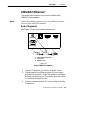
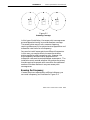
Description
The 6710 Access Point provides transparent, wireless
communications between a wired Ethernet LAN and
wireless stations. Figure 2-1 shows current designs;
information in this user’s guide applies to both designs.
Figure 2-1
6710 Access Points
6710 Access Point User’s Guide
2-1
SECTION 2
"
Features and Functional Overview
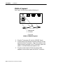
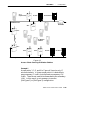
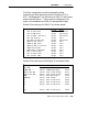
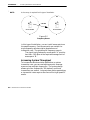
The access point functions as a 4-port translating bridge.
Functionality within the access point can be partitioned
into two major functional blocks: bridging functionality
and management functionality. Bridging functions pertain
to the forwarding of data through the access point.
Management functionality involves configuration, software
upgrade, and network management.
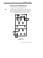
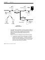
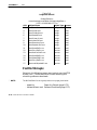
Figure 2-2 is a simplified diagram showing the functions
within the access point.
Management and Configuration
Bridging
MIB
DHCP
SNMP
Agent
Forwarding
Database
TCP/IP
TFTP
File
System
HTTP
Port 2
(NIC 2)
Port 3
(NIC 1)
Port 4
(OWL/IP)
Bridging
Telnet
Proxy ARP
Network
Organization
Device
Configuration
RS-232 Diagnostics Port
Port 1
(Ethernet)
AUI
10BASE2
10BASE-T
Figure 2-2
6710 Access Point Functions
Bridging Functionality
General Concepts
Bridges are common components in wired LANs. Bridges
are devices that join two or more LAN segments. This
provides the appearance of a single LAN segment to the
protocols and applications that operate within the LAN.
2-2
6710 Access Point User’s Guide
SECTION 2
"
Features and Functional Overview
Bridges operate at the Media Access Control (MAC)
sublayer of the Data Link Layer (Layer 2) of the
International Organization for Standardization (ISO)
protocol model. Operating at the MAC layer allows bridges
to operate transparently to commonly used network
protocols such as TCP/IP, Novell SPX/IPX, NetBEUI, and
DECnet.
In wired LANs, bridges do the following:
"
"
"
Segment traffic for better efficiency and performance.
Extend the reach of LANs when cable length or node
limits have been reached.
Translate between different LAN types such as IEEE
802.3 Ethernet and 802.5 Token Ring.
A LAN environment normally consists of a collection of
nodes or stations, each identified by a unique 48-bit
physical address (also called an IEEE address or MAC
address). Data is sent on the LAN as frames or packets
that contain the source address of the station sending the
frame, and the destination address of the recipient station.
A bridge has at least two ports, each connected to a
different LAN segment. Bridges learn which source
addresses are generating traffic on each of their ports. If
the bridge receives a frame with a destination address
corresponding to a source address it has seen on another
port, it forwards the frame to the port. If it receives a
frame where the source and destination addresses are on
the same port, it ignores (drops) the frame, since the
destination node receives the original transmission.
Generally, if a bridge receives a frame for an unknown
destination address on any one port, it floods the frame on
all other ports.
6710 Access Point User’s Guide
2-3
SECTION 2
"
Features and Functional Overview
Access Point Bridging Layer
The 6710 Access Point functions as a bridge with up to four
ports:
An Ethernet port.
" One or two radio ports.
" An Open Wireless LAN/Internet Protocol (OWL/IP)
port.
The access point is a translating bridge because it forwards
frames between Ethernet and wireless media that have
unique physical and MAC protocol implementations. The
access point implements the basic learning and forwarding
functions of a simple wired LAN bridge. It also includes
additional functionality to address unique problems in
wireless LANs.
"
Significant functions supported at the bridging layer
include network organization, support for roaming and
power-managed stations, and programmable flooding levels.
Network Organization
Open wireless LAN networks may be complex, supporting:
Small or large numbers of access points on a single
wired LAN backbone.
" Stations that roam between coverage areas and
employ power management to improve battery life.
More complex topologies include the following:
"
"
"
"
"
"
2-4
Range extension through wireless access points, which
are not connected to the wired LAN backbone.
Secondary LANs (connection of wired LAN segments
by wireless links).
Mixed radio frequency (RF) media.
Operation over multiple IP subnets.
Multiple, independent wireless LANs on one wired
LAN backbone.
6710 Access Point User’s Guide
SECTION 2
"
Features and Functional Overview
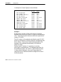
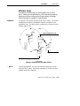
Access points automatically configure into a self-organized
network using a spanning tree topology. They
automatically reconfigure the network to maintain reliable
operation as devices are added or removed, or in the event
of some types of wired LAN failure. The spanning tree
provides efficient, loop-free forwarding of frames through
the network and rapid roaming of mobile stations within
the network.
The spanning tree is initiated by the super root, an access
point that coordinates the network and distributes common
system parameters to other access points and stations. The
super root is elected from a group of access points
designated at the time of installation. The election process
also occurs in the event of a super root failure, preventing a
single point of failure.
Forwarding
The bridge maintains a forwarding database of all physical
station addresses known to the access point, and the correct
port for each address. This database makes efficient
forwarding decisions in the bridging software.
The database is updated through monitoring addresses on
each port, and by messages exchanged between access
points when stations roam. The database also includes the
power management status of each station, supporting the
pending message feature of the network.
Pending Messages
Wireless stations may use power management to maintain
battery life. These stations wake up periodically to receive
messages that may have arrived while their radio was
powered down. The bridging software provides a pending
message delivery service, allowing frames to be held until
the station is ready to receive them.
6710 Access Point User’s Guide
2-5
SECTION 2
"
Features and Functional Overview
Flooding Configurations
Standard LAN bridges flood frames on all ports when the
destination address is unknown. Additionally, many
network protocols use multicast addressing for connection
and status communications. A multicast frame is a special
type of frame destined for more than one physical address.
Standard bridges always flood multicast frames.
Most wireless media supported in the access point operate
at lower media speeds than Ethernet. Indiscriminate
flooding from a busy Ethernet backbone to a wireless
medium can consume a substantial portion of the available
wireless bandwidth. This reduces system performance even
though flooded frames are frequently not intended for
stations on a given wireless segment.
To allow performance tuning, the access point provides
separate flooding control options for both unicast (single
physical address) and multicast frames. Access points
serving as designated bridges connecting wired LAN
segments may be configured to use different flooding
settings than access points serving only wireless stations.
Two of the wireless media supported in the access point —
synthesized UHF (S-UHF) and 900 MHz — provide reliable
attach mechanisms, which guarantee that wireless stations
are always in the access point’s forwarding database.
Unicast flooding is never required for these stations.
The Wireless LAN Interoperability Forum (WLIF) 2.4 GHz
option also provides a reliable attach mechanism for
stations using the NORANDR Network Layer (NNL)
terminal emulation network protocol. Multicast flooding
levels are set for individual networks based on the needs of
wireless stations to receive multicast frames. For networks
with IP wireless stations only, the Proxy ARP Server
provides an option to enabling multicast flooding.
2-6
6710 Access Point User’s Guide
SECTION 2
"
Features and Functional Overview
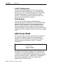
Proxy ARP Server
The Proxy ARP Server is an advanced flooding control
capability for stations using IP. An ARP (Address
Resolution Protocol) is a type of multicast message used to
determine the physical (MAC) address of a station using a
specific IP address. When Proxy ARP is enabled, the IP
addresses of stations using IP are included in the
forwarding database. If the destination IP address matches
an entry in the forwarding database, the ARP is sent to the
physical unicast address matching that IP address.
To allow customization of this capability to optimize
performance, the server operates in one of the following
modes:
"
No flooding.
"
Delayed flooding.
"
Normal flooding.
Proxy ARP Server is discussed in more detail in Section 4,
“Configuration.”
Bridge Ports
The access point has the following physical ports:
"
"
An Ethernet port.
Two PC card slots capable of accepting a variety of
wireless Network Interface Cards (NICs).
The access point also has a logical OWL/IP port.
Ethernet Port
The Ethernet port can be configured to support 10BASE-T
twisted pair, 10BASE2 thinnet, or an AUI connection. The
AUI connection can support 10BASE5 thicknet or 10BASEF
fiber optic connections with the appropriate media
adapters.
6710 Access Point User’s Guide
2-7
SECTION 2
"
Features and Functional Overview
The physical connections are on the bottom panel of the
access point. The desired Ethernet medium is selectable
through the device configuration menus. Section 3,
“Installation,” has more information about connecting the
access point to Ethernet media. Section 4, “Configuration,”
describes how to set the medium through the configuration
menus.
Ethernet Port Filters
The Ethernet port can be configured to support a variety of
preconfigured and custom input filters. Access points are
commonly installed on LANs that carry traffic for wired and
wireless devices. Setting filters prevents unnecessary
traffic from the wired LAN from being forwarded onto the
wireless medium. This is important because common
wireless technologies operate at data rates below Ethernet
speeds.
Normally, filters are set to pass traffic known to be (or
likely to be) destined for wireless stations, and drop traffic
not destined for stations requiring wireless connectivity.
Filtering occurs in the Ethernet driver software that
controls low level operation of the Ethernet ports,
minimizing involvement of other functions when
unnecessary frames are received. In most installations, the
predefined filters are used. The default access point
configuration sets no filters. Filter setup is discussed in
more detail in Section 4, “Configuration.”
Filtering and flooding control (described on page 2-6) are
complimentary but have different functions. Filters allow
frames to be eliminated based upon content of the frame,
usually the network protocol header fields within the frame.
For example, filters can be set to eliminate some or all IP
traffic or Novell IPX traffic.
2-8
6710 Access Point User’s Guide
SECTION 2
"
Features and Functional Overview
Filtering occurs regardless of whether the destination
address is in the forwarding database. Using filters can
improve the performance of the access point and prevent
undesired frames from being forwarded to wireless stations
attached to the access point.
Flooding decisions are made after frames have been
received on a port and filtered. Flooding settings determine
how the access point forwards frames to destination
addresses not in the forwarding database.
Radio Ports
Each of the two radio ports in the access point are a
connection into a LAN segment consisting of all wireless
stations and access points that use the same wireless
technology, are within wireless communications range of
the access point, and are configured to communicate
together.
The two PC card slots are intended for wireless NICs and
are designated as NIC1 and NIC2. Internally, they are
configured as Port 3 and Port 2, respectively. The following
wireless options are currently supported:
WLIF (2.4 GHz).
" 900 MHz.
" 450 MHz S-UHF.
The different media options provide alternative coverage
and throughput tradeoffs. Radio media options are
described in more detail in Appendixes B, C, and D.
"
The access point also supports combinations of two adapters
for operation in mixed media systems; or, for WLIF radios,
a wireless access point capability. The following dual radio
configurations are supported:
"
"
"
WLIF and 900 MHz.
WLIF and S-UHF.
WLIF and WLIF (limited to Master/Slave
configuration for wireless access points).
6710 Access Point User’s Guide
2-9
SECTION 2
"
Features and Functional Overview
Configuration of individual radio options and the WLIF
wireless access point configuration are discussed in Section
4, “Configuration.”
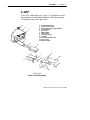
OWL/IP Port
The OWL/IP port is a logical port used in installations
where the wireless infrastructure is required to operate
across multiple IP subnets; that is, in installations where
IP routers are used.
The OWL/IP port is an advanced capability that allows
stations supporting IP and nonroutable protocols such as
NNL (used in some terminal emulation installations) to
roam without losing connectivity when a wireless LAN
installation must extend over multiple IP subnets. In some
cases, OWL/IP may also provide connectivity in larger,
routed networks when roaming between IP subnets is not
required, but where it is desirable to configure a single
wireless network across router boundaries.
OWL/IP uses General Router Encapsulation (GRE), a
registered protocol from the TCP/IP protocol suite. GRE
allows frames destined for stations on a different IP subnet
to be encapsulated with an IP address that passes
transparently through routers. Encapsulation is also
sometimes referred to as tunneling.
To simplify configuration, OWL/IP functionality is treated
as an additional port within the access point architecture.
It is a logical port in that there is no physical radio or wired
LAN port associated with OWL/IP.
Encapsulated frames may be sent through any of the three
physical ports. Access points separated by one or more
routers may be thought of as originating and receiving
nodes on the two sides of a tunnel that is established
through the router.
2-10
6710 Access Point User’s Guide
SECTION 2
"
Features and Functional Overview
The forwarding database entry for a station on the other
side of the tunnel includes the physical port (NIC1, NIC2,
or Ethernet) the frame should be forwarded through, and
an indication that encapsulation is required. The receiving
access point on the other side of the tunnel de-encapsulates
the frame and then forwards it on the correct physical port.
OWL/IP is described in more detail in Section 4,
“Configuration,” and Appendix E, “OWL/IP.”
Configuration and Management
Configuration
The access point can be configured through a local RS-232
connection, or remotely through a TCP/IP connection. The
access point includes a command monitor and menu driven
configuration with online help. The command monitor and
file system configuration are contained in permanent
read-only memory (ROM) within the access point, and can
be accessed through the RS-232 diagnostics port even if
software is not loaded in the access point.
Most access point functionality is provided by the software
stored within the file system. Configuration parameters
are stored in nonvolatile EEPROM memory, and are
maintained in the event of power loss.
Diagnostics and Configuration Port
An RS-232 configuration port is provided for direct access to
the access point’s command monitor and configuration
menus. Access through the diagnostics port is
password-protected for security.
6710 Access Point User’s Guide
2-11
SECTION 2
"
Features and Functional Overview
The port uses a standard PC AT style cable, and operates at
speeds up to 57.6 Kbps. Configuration using this port is
described in Section 4, “Configuration.”
Remote Access
Remote access is available over TCP/IP connections using
Telnet or Hypertext Transfer Protocol (HTTP) for
configuration management, and Simple Network
Management Protocol (SNMP) for network management.
TCP/IP
The access point supports remote access through a Request
for Comments (RFC) compliant TCP/IP stack. Before initial
usage, the stack must be initially configured with an IP
address and an optional default router through the RS-232
diagnostics port. Alternatively, the access point may be
configured with a Dynamic Host Configuration Protocol
(DHCP) server name. The access point then obtains its IP
address, default router, and subnet mask from a DHCP
server.
DHCP Client
The access point contains a DHCP client, allowing it to
receive an IP address over the network. The DHCP client
supports temporary and permanent leases. It also accepts
permanent leases from a Bootstrap Protocol (Bootp) server.
See Section 4, “Configuration,” for further detail on DHCP
operation.
Telnet
Telnet may be used to access the access point’s
configuration menus. The command interface is identical to
the command interface through the diagnostics port. See
Section 4, “Configuration,” for more information about
access through Telnet.
2-12
6710 Access Point User’s Guide
SECTION 2
"
Features and Functional Overview
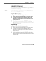
HTTP
The access point supports configuration using HTTP from a
workstation equipped with a Web browser. Internet
Explorer or Netscape Navigator is recommended. See
Section 4, “Configuration,” for more information about
access through a Web browser.
Electronic Software Distribution
The access point supports electronic software distribution,
which allows software upgrades after installation. The
access point provides a dual bank file system with one
active bank and one inactive bank. It operates from the
active bank, allowing software upgrades to be stored in the
inactive bank. This enables upgrades to be loaded while
the access point is operating.
The upgrade can be started immediately after downloading
by swapping the active and inactive banks and rebooting.
The access point can also be programmed to load the new
software at a later time, such as after all access points have
been upgraded or during a time of little system activity.
TFTP Client and Server
Software downloads are accomplished using the Trivial File
Transfer Protocol (TFTP), another member of the IP suite.
Each access point contains a TFTP client and server. The
TFTP client allows the access point to obtain software
updates from a TFTP server. The server can be an access
point configured with the TFTP server enabled, or another
network workstation with TFTP server capability.
Scripting
The access point supports a scripting capability that
automates most of the software download process. Scripts
can be uploaded to the access point through Telnet or
SNMP.
6710 Access Point User’s Guide
2-13
SECTION 2
"
Features and Functional Overview
Network Management
The access point is instrumented for network management,
with variables defined in the Management Information
Base (MIB). The MIB is SNMP V1 compliant.
Management information can be accessed through the
SNMP agent. The MIB may be ordered separately and
compiled for any SNMP network management platform.
Additional capabilities are supported in the OWLView
network management application for HP OpenView.
Appendix G, “MIB,” contains the 6710 Access Point MIB.
Consult the following documentation for more information
on network management:
"
"
"
NORAND Open Wireless LAN with HP OpenView for
Windows User’s Guide (961-051-009)
OWLView for HP OpenView for UNIX User’s Guide
(961-051-011)
OWLView for HP OpenView for Windows User’s Guide
(961-051-010)
Sample Configuration
Figure 2-3 shows a sample network configuration. It also
shows access points providing additional coverage and
wireless links to secondary Ethernet LANs.
" NOTE:
2-14
Consult Appendix D, “S-UHF Specifications and Antennas,” for
network configuration limitations for S-UHF systems.
6710 Access Point User’s Guide
SECTION 2
Features and Functional Overview
Terminal Emulation
Gateway
Host
LAN Server
"
Distribution LAN
6710 Access Point
6710 Access Points
Wireless Hop
6710 Access Point
(Designated Bridge)
Secondary Ethernet LAN
PEN*KEYR 6400
Computer
Notebook
(WLIF)
Desktop
PEN*KEY 6400
Computer
Figure 2-3
Sample Network Configuration
6710 Access Point User’s Guide
2-15
SECTION 2
"
Features and Functional Overview
Components
Figure 2-4 shows access point components, described on the
following pages. Not shown is the mounting bracket, which
attaches the access point to a wall or ceiling.
Figure 2-4
Access Point Components
2-16
6710 Access Point User’s Guide
SECTION 2
"
Features and Functional Overview
1. Protective cover. The cover protects two Type II or
Type III PC card slots. Figure 2-5 shows where the
slots are located.
1
1
1. PC card slots
Figure 2-5
PC Card Slots
2. Indicator lights. Four pairs of indicator lights
(LEDs) on the front panel show the status of the
access point. During the power-up sequence, the
lights show the results of the power-up self diagnostics
and provide information about the operating status.
After the power-up sequence, the lights show the
current operating status and indicate if a problem
exists. Section 6, “Indicator Lights,” describes the
lights in detail.
6710 Access Point User’s Guide
2-17
SECTION 2
"
Features and Functional Overview
3. Rubber feet. Four nonskid rubber feet provide a
stable base for the access point when you place it on a
desktop or other horizontal surface.
When the mounting bracket is installed for an access
point mounted vertically or on the ceiling, the rubber
feet provide a small amount of tension to the bracket
to help hold it in place.
4. AC INPUT. The AC INPUT connector is a standard
IEC type, three-prong AC input connector. The power
cord attaches to this connector. The internal power
supply is an autosensing international power supply.
It accepts a source voltage between 85 and 264 V ac,
with a frequency between 47 and 63 Hz.
5. 10 BASE 2. The 10 BASE 2 port is a standard BNC
port through which the access point connects to
10BASE2 Ethernet (thinnet).
6. 10 BASE T. The 10 BASE T port is a standard RJ45
port through which the access point connects to
10BASE-T (UTP) Ethernet.
7. AUI. The AUI port is a 15-pin, D-subminiature
(D-sub) port. The access point connects to an AUI
network adaptor through this port, for connection to
10BASE5 Ethernet (thicknet). Appendix F, “Port and
Cable Pin-Outs,” contains pin definitions.
" NOTE:
Section 3, “Installation,” shows how to connect the access point to
10BASE2, 10BASE5, and 10BASE-T.
8. DIAG. The DIAG port is a 9-pin D-sub
communication port that communicates at RS-232
levels. Use this port to configure the access point,
download new software, and retrieve statistics.
Appendix F contains pin definitions.
2-18
6710 Access Point User’s Guide
SECTION 2
"
Features and Functional Overview
Accessories
Power Cord
The power cord connects the access point to the wall outlet.
The following chart lists power cord part numbers.
Country
Part Number
Australia
321-472-001
Denmark
321-501-001
Europe
321-473-001
Italy
321-471-001
Germany
321-515-001
United Kingdom
321-474-001
United States
321-054-001
Industrial Locking Mounting
Bracket
The Industrial Locking Mounting Bracket “locks” the access
point into the bracket. This bracket is recommended for
installations where vibration, shaking, or other movement
can dislodge the access point from its mount.
Item
Part Number
Mounting kit
203-386-001
6710 Access Point User’s Guide
2-19
SECTION 2
2-20
"
Features and Functional Overview
6710 Access Point User’s Guide
Section 3
Installation
"
"
"
"
"
"
"
"
"
"
"
"
"
"
"
"
"
"
"
"
"
"
"
"
"
"
"
"
This section describes how to:
"
"
"
"
"
"
"
Check the access point’s default configuration.
Prepare for the installation.
Collect the networking equipment you need.
Find the best location.
Connect to the Ethernet medium.
Install PC cards.
Apply power.
Checking the Default Configuration
The access point is shipped with default settings for system
software parameters, which are listed in Section 4,
“Configuration.” You may need to change some default
settings to achieve a more efficient configuration for your
site. See Section 4 for information about reconfiguring the
access point. The access point should be properly
configured before it is connected to the network.
6710 Access Point User’s Guide
3-1
SECTION 3
"
Installation
Preparing for the Installation
" NOTE:
Someone who knows and understands all applicable local building
codes and is proficient with the tools and equipment used to install
FCC Class B electromechanical devices should physically install the
access point.
Before you install the access point, unpack it and inspect it
for damage or missing parts. Save all the paperwork you
received. If the access point appears to be damaged, contact
the Customer Response Center for instructions on
returning the unit for replacement.
The shipment contains the access point with FLASH and
the following items:
"
"
"
Mounting bracket
AC power cord
Warranty card
Collecting the Equipment
Before you install the access point onto the network, collect
the equipment you will need.
Ethernet LAN Components
The access point directly connects to 10BASE2, 10BASE-T,
or 10BASE5 Ethernet medium. Consult a cabling reference
for maximum run lengths and node limits for Ethernet
wiring.
3-2
6710 Access Point User’s Guide
SECTION 3
"
Installation
10BASE2 Components
10BASE2 components include a T-connector, a cable
terminator, and the proper lengths of 10BASE2 coax cable.
The 10BASE2 T-connector (Figure 3-1) attaches to the
access point’s 10BASE2 port, and connects the access point
to the middle or end of 10BASE2 cable.
Figure 3-1
T-Connector
A cable terminator (Figure 3-2) attaches to the
T-connector. It is required for a device connected to the end
of 10BASE2 cable. The terminator properly terminates the
network cable to maintain proper impedance. Proper
termination is necessary for reliable Ethernet operation.
Figure 3-2
Cable Terminator
10BASE-T Component
10BASE-T coax cable is normally used to connect the
access point to an Ethernet hub. The cable has an RJ45
plug on each end (Figure 3-3).
Figure 3-3
Cable With RJ45 Plugs
6710 Access Point User’s Guide
3-3
SECTION 3
"
Installation
10BASE5 Components
10BASE2 components include the proper lengths of
10BASE5 coax cable, an AUI drop cable (less than or equal
to 50 feet/15 meters long), and a transceiver. Two types of
transceivers are the intrusive N-Series transceiver and the
nonintrusive vampire tap.
The N-Series transceiver (Figure 3-4) is a T-shaped
connector with a 15-pin AUI port and two type N
connectors. This transceiver is intrusive because network
service is disrupted while the coaxial cable is cut and a
threaded N-series connector placed on each end of the cable.
A 10BASEF (fiber optic) adapter may be attached directly
to the AUI connector.
Figure 3-4
N-Series Transceiver
The vampire tap is an insulation-piercing clamp device that
clamps onto the coaxial cable (Figure 3-5). The vampire tap
pierces the coaxial cable’s insulation and makes contact
with the shield and inner conductor without cutting the
cable.
3-4
6710 Access Point User’s Guide
SECTION 3
"
Installation
Figure 3-5
Vampire Tap
Communication Equipment
You can access the access point’s system software
configuration menus locally through the unit’s DIAG port,
or remotely through a Telnet session or Web browser.
Local DIAG Port Access
For local access, you need the following:
"
"
"
Third-party communications software terminal
emulation package with Y-modem capability (such as
PROCOMM PLUS by DataStorm Technologies, Inc.).
Install the program according to its user guide.
PC (personal computer) station, which should meet
the requirements outlined in the user guide for the
terminal emulation program.
Cable to connect the PC to the access point’s DIAG
port. The following chart lists cables.
6710 Access Point User’s Guide
3-5
SECTION 3
"
Installation
For this PC Port
Use Cable Part Number
9-pin
25-pin
226-106-001 (null modem cable)
321-355-001
Telnet
You need the following to access the configuration menus
through a Telnet session:
"
"
"
PC or workstation with an installed and configured
network interface card and a Telnet application. You
can also use a host capable of acting as a Telnet client.
Telnet VT emulator (TNVT) installed on the PC.
IP address for the access point. See Section 4 for more
information about IP addresses.
Web Browser
The access point’s configuration menus are designed for
HTML Level 2.0 or higher. You need the following to access
the configuration menus through a Web browser:
"
"
"
Graphical browser application.
Internet or local network connection.
IP address for the access point. See Section 4 for more
information about IP addresses.
Network Management Platform
To manage the system through a network management
platform, you need the platform (such as OpenView for
Windows by Hewlett-Packard) installed on a network
management station using SNMP. The station must meet
the requirements outlined in the platform’s user guide.
3-6
6710 Access Point User’s Guide
SECTION 3
"
Installation
Finding the Best Location
Site Survey
Intermec strongly recommends that Intermec or certified
providers conduct a site survey to determine the ideal
locations for all of your network components. A proper site
survey requires special equipment and training. A site
survey provides an installation recommendation that
addresses various factors, which can affect the performance
of your wireless LAN system.
General Installation Guidelines
Coverage in most sites requires a network of access points
to be installed. Radio coverage varies greatly with factors
such as building construction, number and type of
obstructions in the signal path, and the RF media in use.
Additional factors related to the intended use of the system
also dictate installation practices. The following general
practices should be followed in any installation:
"
"
"
"
"
Locate access points centrally within areas requiring
coverage.
Try to position the access point so its indicator lights
are visible. The lights are useful for troubleshooting
the installation.
Position antennas below roof trusses and away from
I-beams, racks, or other structures and obstructions.
Overlap access point coverage areas to avoid coverage
holes.
Install wired LAN cabling within node limit and cable
length limitations.
6710 Access Point User’s Guide
3-7
SECTION 3
"
Installation
"
"
"
Ensure that a power outlet is within 6 feet of the
access point. An uninterruptable power supply is
recommended when the ac power system is not
reliable.
Ensure that LAN and ac cables can reach the access
point after you install it. Leave sufficient room
around the access point so you can easily attach and
remove cables.
Do not locate an access point with the S-UHF radio
option in a computer room. RF emissions from the
higher speed processors in current-generation
computers may reduce system range.
Mounting the Access Point
You can mount the access point horizontally on a tabletop,
vertically on a wall or post, or on the ceiling.
Horizontal (Tabletop) Mount
1. Remove the mounting bracket from the bottom of the
access point. The bracket is not needed for a tabletop
installation.
2. Set the access point in position. The unit rests
securely on four rubber feet that keep it from slipping
out of place.
3. Make all Ethernet connections. See “Connecting to
Ethernet” on page 3-10.
4. Make all power connections. See “Applying Power” on
page 3-20.
5. Watch the indicator lights to verify that the access
point is working properly. See Section 6, “Indicator
Lights,” for help.
3-8
6710 Access Point User’s Guide
SECTION 3
"
Installation
Vertical and Ceiling Mounts
See Figure 3-6 and the procedure following it.
" NOTE:
If mounting the access point on a hollow wall, secure the mounting
plate to a 3/4” (thick) plywood base by four 1” X 1/4” nuts, bolts, and
washers. Anchor the plywood base to two separate wall studs by
four 2” X 1/4” diameter lag screws (two lag screws in each stud).
6.00"
1.00"
2.00"
1.00"
2.00”
1.00"
Figure 3-6
Mounting Bracket
6710 Access Point User’s Guide
3-9
SECTION 3
"
Installation
1. Inspect where the access point will be mounted and
determine what hardware is needed. Different
surfaces such as drywall, wood, and concrete block
require different mounting hardware. For this reason,
a universal mounting bracket is included with the
access point.
2. Remove the mounting plate from the bottom of the
access point.
3. Using the mounting plate as a template, mark where
the anchors that secure the mounting plate to the
surface should be located.
4. Attach the access point mounting plate to the wall or
ceiling with 2I x 1/4I diameter lag screws or bolts,
depending upon the surface. The mounting plate
must be secured to the surface by at least four
anchors, one on each corner.
5. Reattach the access point to the mounting plate.
6. Make all Ethernet connections. See “Connecting to
Ethernet.”
7. Make all power connections. See “Applying Power” on
page 3-20.
8. Watch the indicator lights to verify that the access
point is working properly. See Section 6, “Indicator
Lights,” for help.
" NOTE:
An optional locking kit is available. See Section 2, “Features and
Functional Overview,” for more information.
Connecting to Ethernet
The following pages show how to connect the access point to
10BASE2, 10BASE5, and 10BASE-T Ethernet.
3-10
6710 Access Point User’s Guide
SECTION 3
"
Installation
10BASE2 Ethernet
The access point connects to the end or middle of the
10BASE2 cable segment.
" NOTE:
Cable lengths between network devices on the 10BASE2 Ethernet
LAN must meet ANSI/IEEE standards.
End of Segment
See Figure 3-7 and the procedure following it.
10 BASE 2
10 BASE T
DIAG
AUI
AC INPUT
100/240 VAC
1
2
3
1. Cable terminator (50 ohm)
2. T-connector
3. 10BASE2 cable
Figure 3-7
End of 10BASE2 Segment
1. Plug the T-connector (2) into the 10 BASE 2 port.
2. Plug one end of the Ethernet cable (3) into an open
end of the T-connector. Align the notches in the cable
end with the posts on the T-connector, push the cable
in, and twist one-quarter turn.
3. Plug the cable terminator (1) into the other end of the
T-connector.
6710 Access Point User’s Guide
3-11
SECTION 3
"
Installation
Middle of Segment
See Figure 3-8 and the procedure following it.
10 BASE 2
10 BASE T
DIAG
AUI
AC INPUT
100/240 VAC
1
2
1
1. 10BASE2 cable
2. T-connector
Figure 3-8
Middle of 10BASE2 Segment
1. Plug the T-connector (2) into the 10 BASE 2 port.
2. Plug one end of the Ethernet coaxial cable (1) into an
open end of the T-connector. Align the notches in the
cable end with the posts on the T-connector, push the
cable in, and twist about one-quarter turn.
3. Plug the end of another Ethernet coaxial cable
segment into the other open end of the T-connector.
3-12
6710 Access Point User’s Guide
SECTION 3
"
Installation
10BASE5 Ethernet
The access point connects to 10BASE5 through an N-Series
transceiver or vampire tap.
" NOTE:
Cable lengths between network devices on the 10BASE5 Ethernet
LAN must meet ANSI/IEEE standards.
N-Series Transceiver
See Figure 3-9 and the following procedure.
1. Attach one end of the drop cable (1) to the AUI port.
2. Route the drop cable to the 10BASE5 cable (4) and
determine a suitable spot to cut the cable and attach
the transceiver (3).
3. Attach the transceiver to the 10BASE5 cable, then
connect the other end of the drop cable to the AUI port
(2) on the transceiver.
Vampire Tap
See Figure 3-10 and the following procedure.
1. Attach one end of the drop cable (1) to the AUI port.
2. Route the drop cable to the 10BASE5 cable and
determine a suitable spot on the cable to attach the
vampire tap (3).
3. Attach the vampire tap to the 10BASE5 cable, then
connect the other end of the drop cable to the AUI port
(2) on the tap.
6710 Access Point User’s Guide
3-13
SECTION 3
"
Installation
10 BASE 2
DIAG
AUI
10 BASE T
AC INPUT
100/240 VAC
1
3
2
4
1.
2
3.
4.
Drop cable
15-pin AUI port
N-Series transceiver
10BASE5 coax
Figure 3-9
N-Series Transceiver
3-14
6710 Access Point User’s Guide
4
SECTION 3
10 BASE 2
10 BASE T
"
Installation
DIAG
AUI
AC INPUT
100/240 VAC
1
3
2
4
1.
2.
3.
4.
4
Drop cable
15-pin AUI port
Vampire tap
10BASE5 coax
Figure 3-10
Vampire Tap
6710 Access Point User’s Guide
3-15
SECTION 3
"
Installation
10BASE-T Ethernet
See Figure 3-11 and the procedure following it.
10 BASE 2
10 BASE T
AUI
DIAG
AC INPUT
100/240 VAC
1
1. Cable with RJ45 plugs
2. RJ45 jack (or hub port)
Figure 3-11
10BASE-T
1. Plug the cable with RJ45 jacks (1) into the 10 BASE T
port.
2. Plug the other end of the cable into RJ45 jack or hub
port (2).
3-16
6710 Access Point User’s Guide
SECTION 3
"
Installation
Installing PC Cards
The following pages describe how to install WLIF, 900 MHz,
and S-UHF PC cards.
WLIF
The WLIF radio option is a Type III PC card that can be
installed in either slot. To install the card, see Figure 3-12.
1
2
3
4
5
6
4
7
1.
2
3.
4.
5.
6.
7.
Nonskid rubber feet (4)
Access point (no radio)
PC card (RM180)
Antenna cable
End plate
4-- 40 captive thumb screws
Hex nut and lock washer (supplied with antenna cable)
Figure 3-12
WLIF PC Card Assembly
6710 Access Point User’s Guide
3-17
SECTION 3
"
Installation
900 MHz
The 900 MHz radio option is a Type III PC card that can be
installed in either slot. To install the card, see Figure 3-13.
1
2
3
4
5
4
6
7
1.
2
3.
4.
5.
6.
7.
Nonskid rubber feet (4)
Access point (no radio)
PC card (RM160)
Antenna cable
End plate
4-- 40 captive thumb screws
Hex nut and lock washer (supplied with antenna cable)
Figure 3-13
900 MHz PC Card Assembly
3-18
6710 Access Point User’s Guide
SECTION 3
Installation
"
S-UHF
The S-UHF radio option is a Type II PC card that can only
be installed in the left-hand slot (with LEDs facing down).
To install the card, see Figure 3-14.
1
1.
2
3.
4.
5.
6.
7.
8.
9.
10.
11.
12.
2
3
4
Nonskid rubber feet (4)
Access point (no radio)
Sliding latch (open for RM111 adapter)
PC card (RM111)
Flex circuit
RM111 adapter
Radio bracket
Conductive washer
End plate
4-- 40 captive thumb screws
4-- 40 x .25 PH
Antenna adapter
5
6
9
7
10
8
11
12
Figure 3-14
S-UHF PC Card Assembly
6710 Access Point User’s Guide
3-19
SECTION 3
"
Installation
Applying Power
B CAUTION:
NEVER remove the cover of the access point with power
applied. ALWAYS make the access point connection before
making the connection at the source (“load to source”).
Damage to the radio or other devices can occur with the cover
removed.
" NOTE:
Connect the access point to an uninterruptable power source — a
power source that cannot be inadvertently turned off or otherwise
disconnected.
Power is applied to the access point through the grounded
AC INPUT connector. See Figure 3-15 and the following
procedure.
1. Plug the receptacle end of the power cord (1) into the
AC INPUT connector.
2. Insert the three-prong plug on the other end of the
power cord (2) into a grounded power outlet.
3. See Section 6, “Indicator Lights,” for descriptions of
the indicator lights.
3-20
6710 Access Point User’s Guide
SECTION 3
10 BASE 2
10 BASE T
"
Installation
DIAG
AUI
AC INPUT
100/240 VAC
1
2
1. Receptacle on power cord
2. Three-prong plug
Figure 3-15
AC Power Input Connection
6710 Access Point User’s Guide
3-21
SECTION 3
3-22
"
Installation
6710 Access Point User’s Guide
Section 4
Configuration
"
"
"
"
"
"
"
"
"
"
"
"
"
"
"
"
"
"
"
"
"
"
"
"
"
"
"
"
This section describes how to:
Create a local DIAG port, Telnet, and Web browser
session with the access point.
" Access the access point’s FLASH and ROM.
" Set up the access point through its configuration
menus.
You can configure the access point locally through its DIAG
port, or remotely through Telnet or a Web browser. The
following chart shows the sessions you can use to do other
tasks.
"
Task
DIAG Port
Telnet
Browser
Change configuration passwords
Modify the configuration
Ö
Ö
Ö
Ö
Ö
Ö
Upgrade FLASH
Ö
Ö
Check the FLASH version
Ö
Ö
Access ROM
Ö
Check the ROM version
Ö
Use online help
Ö
Ö
Ö
6710 Access Point User’s Guide
4-1
SECTION 4
"
Configuration
Only one type of session can be running at a time. For
example, if someone starts a Telnet session while someone
else is configuring the access point through its DIAG port,
the configuration through the DIAG port will terminate.
Creating a Local DIAG Port Session
In summary, you establish a local DIAG port session with
the access point through a VT100 terminal emulation
program. Most general purpose communications software
(such as PROCOMM PLUS) supports this emulation.
To create a session, see Figure 4-1 and the procedure
following it. You should carefully review the procedure first
to become familiar with the process.
4-2
6710 Access Point User’s Guide
SECTION 4
"
Configuration
1
2
3
10BASE2
10BASET
AUI
DIAG
AC INPUT
100/240 VAC
1. PC with terminal emulation program
2. Cable: 321-355-001 for a 25-pin PC COM port
or
Cable: 226-106-001 for a 9-pin PC COM port
(standard null modem cable)
3. 6710 Access Point DIAG port
Figure 4-1
Local Session
1. Ensure the terminal emulation program is installed
on the PC.
2. With both the PC and access point powered OFF,
connect the communication cable to the appropriate
PC COM port.
6710 Access Point User’s Guide
4-3
SECTION 4
"
Configuration
3. Connect the other end of the communication cable to
the DIAG port on the access point. Turn the PC on.
4. After the PC boots, start the terminal emulation
program.
5. Set the terminal emulation program’s options
according to what you want to do: Access the
configuration menus, or access the ROM command
monitor.
Accessing the Configuration
Menus
1. Set the terminal emulation parameters in your
communications software. If you are configuring this
access point for the first time, set the parameters to
the access point’s default settings:
9600, 8N1, full duplex
If you have already changed the default settings, set
the parameters to those you set in FLASH mode
through the configuration menus.
2. Plug the access point into the outlet. These messages
appear:
QXS6700K <version> <date>
<Press any key within 5 seconds to enter the ROM monitor>
Executing file USTART29.BIN from segment <segment number>
Quickly press a key to perform configuration before startup
Starting system
3. To access the configuration menus, wait until you see
the message “Quickly press a key to perform
configuration before startup.” Press any key to access
the configuration menus.
4. See “Configuring the Access Point” on page 4-12.
4-4
6710 Access Point User’s Guide
SECTION 4
"
Configuration
Accessing the ROM Command
Monitor
1. Set the terminal emulation parameters in your
communications software. If you are configuring this
access point for the first time, set the parameters to
the default settings for ROM mode:
9600, 8N1, full duplex
If you have already changed the default settings, set
the parameters to those you set in ROM mode through
the ROM command monitor.
2. Plug the access point into the outlet. These messages
appear:
QXS6700K <version> <date>
<Press any key within 5 seconds to enter the ROM monitor>
Executing file USTART29.BIN from segment <segment number>
Quickly press a key to perform configuration before startup
Starting system
3. Press any key within 5 seconds of the first ROM
message.
Note that if the access point is in Power-Up Quiet
mode (versus Power-Up Normal mode, the default
setting), the ROM messages do not display. More
information about Power-Up Quiet (PQ) mode and
Power-Up Normal (PN) mode starts on page 5-27 in
Section 5, “Software Download.”
4. See page 5-22 in Section 5, “Software Download,” for
information about the ROM command monitor.
6710 Access Point User’s Guide
4-5
SECTION 4
"
Configuration
Creating a Telnet Session
Before you can configure the access point through Telnet,
you must connect the unit to the Ethernet cable. (See
Section 3, “Installation,” for help.) You must also perform
initial configuration through the DIAG port to:
"
"
" NOTE:
Set an IP address or DHCP server name. You should
also configure a subnet mask and IP router address.
Set the Ethernet cable type.
The access point includes an autodetect feature that senses the
Ethernet medium if traffic is present. If no traffic is present on the
cable, the system software defaults to 10BASE-T. For most
installations, it is recommended that you explicitly set the Ethernet
type.
The access point must go through its boot sequence before
you can create a Telnet session. If you reboot the unit while
in a session, the session terminates. You can create a new
session after the unit reboots.
To create a Telnet session, see Figure 4-2 and the procedure
following it.
Ethernet LAN
Telnet
1
2
1. PC or workstation with Telnet VT emulator (TNVT)
2. 6710 Access Point
Figure 4-2
Telnet Session
4-6
6710 Access Point User’s Guide
SECTION 4
"
Configuration
1. Ensure the access point is connected to the Ethernet
cable, and has an assigned IP address and cable type.
2. Ensure the PC or workstation has an installed and
configured Ethernet interface card.
3. Ensure the Telnet VT emulator is installed on the PC
or workstation.
4. Open a new Telnet session on the PC or workstation.
5. Enter the access point’s IP address in the host name
or IP address field.
6. See “Configuring the Access Point” on page 4-12.
Default and Site Settings
The access point is factory configured with the default
settings listed in the following charts. You may need to
change the defaults to match the way your system is set up.
You can record your site’s settings in the table for reference.
TCP/IP
Option
Default
IP Address
IP Subnet Mask
IP Router
IP Frame Type
DHCP
0.0.0.0
255.255.255.0
0.0.0.0
DIX
Enabled, if IP Address is zero
Norand DHCP Server
5
DHCP Server Name
Auto ARP Minutes
Site Setting
6710 Access Point User’s Guide
4-7
SECTION 4
"
Configuration
Security
Option
Default
Password
Service Password
Advanced Password
CR52401
Enabled
“” (empty string)
Site Setting
Bridge
Option
Default
Serial Number
Lan ID
[Root]
Root Priority
[Global Radio]
UHF Rfp Threshold
Set Globally
Value
UHF Frag Size
Set Globally
Value
Falc Frag Size
Set Globally
Value
Awake Time
Set Globally
Value
[Global Flooding]
Inbound
Multicast
Unicast
Outbound to Secondaries
Multicast
Unicast
Outbound to Stations
Multicast
Unicast
(Read-only)
0
4-8
6710 Access Point User’s Guide
1
Disabled
70
Disabled
250
Disabled
250
Disabled
0
Primary
Disabled
Disabled
Disabled
Disabled
Disabled
Site Setting
SECTION 4
Option
[Ports]
Ethernet port:
Name
MAC Address
Status
Hello Period
[Ethernet]
OWL Frame Type
Cable Type
[Static Addresses]
[Normal RX Filter]
[Frame Types]
Action
Scope
[SubTypes 1]
Action
SubType
Scope
[SubTypes 2]
Action
SubType
Scope
[Advanced RX Filter]
[Expressions]
ExprSeq
Offset
Op
Value Id
Action
[Values]
Value
[Bridging]
Bridge Priority
Status
Flood Register
Default
"
Configuration
Site Setting
omde
(Unique number)
Enabled
2 seconds
DIX
Auto Detect
00:00:00:00:00:00
Pass
Unlisted
Pass
(Various)
(Various)
Pass
DIX--IP--TCP--Port
00 00
0
0
EQ
0
And
0
1
Enabled
Disabled
6710 Access Point User’s Guide
4-9
SECTION 4
"
Configuration
Option
WLIF radio port:
Name
MAC Address
Status
Hello Period
[WLIF]
Security Id
Node Type
[Master Parms]
Channel
Subchannel
Wireless Hops
MAC Config
[Manual MAC Parms]
Hop Period
Beacon Frequency
Deferral Slot
Fairness Slot
Fragment Size
Transmit Mode
Norm Ack Retry
Frag Ack Retry
Norm QFSK Retry
Frag QFSK Retry
900 MHz radio port:
Name
MAC Address
Status
Hello Period
[Falcon]
File Name
Mode--Channel
ARP Server Mode
4-10
6710 Access Point User’s Guide
Default
omdpxma
(Unique number)
Enabled
2 seconds
NORANDOWL
Master
1
1
Disabled
Default
200 ms
2
Default
Default
310
AUTO
255
255
255
255
omdflca
(Unique number)
Enabled
1 second
falcon_d.29k
(First mode in list)
Disabled
Site Setting
SECTION 4
Option
S-UHF radio port:
Name
MAC Address
Status
Hello Period
[UHF]
File Name
Call Sign
Frequency
Master Mode
Attach Priority
OWL/IP port:
Name
MAC Address
Status
Hello Period
[OWL/IP]
Mode
[IP Addresses]
Type
Address
[TX Filter]
[Frame Types]
Action
Scope
[SubTypes 1]
Action
SubType
Scope
[SubTypes 2]
Action
SubType
Scope
Default
"
Configuration
Site Setting
omduhfb
(Unique number)
Enabled
2 seconds
synuhf_d.29k
“” (empty string)
(First frequency in list)
Disabled
High
omdip
(Unique number)
Enabled
2 seconds
Listen
Unicast
(None)
Pass
Unlisted
Pass
(Various subtypes)
(Various settings)
Pass
DIX--IP--TCP--Port
00 00
6710 Access Point User’s Guide
4-11
SECTION 4
"
Configuration
Configuring the Access Point
When you create a local DIAG port or remote Telnet session
with the access point, the configuration program’s password
screen appears:
Configuration of Access Point
Copyright (c) 1995-1997 Norand Corporation.
All rights reserved.
Portions copyright Epilogue Technology Corporation 1988-1995.
All rights reserved
IP:
Serial:
0.0.0.0
(Unique 10-digit number.)
Password:
" NOTE:
A different screen appears when you create a session through a
Web browser. See page 4-88 for information about Web browser
sessions.
The password screen shows the current settings for the IP
address and serial number. It also shows the prompt for
the top-level password. Enter the password (case
insensitive) to display the Main Menu. The default
password is CR52401.
Main Menu
After you enter the top-level password, the Main Menu
appears:
4-12
6710 Access Point User’s Guide
SECTION 4
"
Configuration
Loading configuration from EEPROM
Command
File
View
Clear
Read
Write
Reboot
Exit
?
Description
File system menu
View/modify the configuration
Set the configuration to default values
Read the configuration from EEPROM
Write the configuration to EEPROM
Restart using last written configuration
Disconnect
Display this help
>
The menu lists the commands you can use to do various
tasks, described on the following pages. The screen also
displays the command prompt (>). At the prompt, type the
name of the command you want to perform and press
[Enter]. (Commands are case insensitive.) The Main Menu
redisplays when you enter an invalid command.
The following chart describes how to use the commands.
Use
To
File
List file system commands and descriptions.
Section 5, “Software Download,” describes the
commands and file system methodology.
View or modify configuration program settings.
See “Using the View Command” on page 4-14.
View
Clear
Read
Reset the access point’s configuration to the factory-set default settings, which start on page 4-7.
Load the most recent configuration from
EEPROM. The configuration that was written to
EEPROM since the access point was last
rebooted becomes the new configuration.
6710 Access Point User’s Guide
4-13
SECTION 4
"
Configuration
Use
To
Read
The access point’s configuration is stored in
(Continued) EEPROM. You reprogram the EEPROM
whenever you change the configuration, write
(save) the new configuration to EEPROM, and
reboot the access point.
Write
Write (save) a new configuration to EEPROM.
This command overwrites the previous configuration. You must write the new configuration
to EEPROM and reboot the access point for
any changes to take effect.
Reboot
Reboot the access point. You must reboot the unit
for any changes you made to the configuration to
take effect.
Exit
Quit the configuration program. If you exit a new
configuration without writing it to EEPROM, any
changes you made are not saved.
?
Display online help for a command, option, or
setting.
Using the View Command
To view or modify configuration program settings, type
View at the command prompt. The Main Options Menu
appears:
[Tcpip]
[Bridge]
[Security]
The following chart describes how to use the options.
4-14
6710 Access Point User’s Guide
SECTION 4
"
Configuration
Use
To
[Tcpip]
Page 4-16
Set options necessary for communications with
this access point. The options apply to all
TCP/IP ports. Telnet, SNMP, and HTTP
communications are supported.
Control the bridging of messages among the
radio and Ethernet ports for this access point.
Settings to control interaction with other access
points are also under the [Bridge] option.
Set the configuration program’s top-level
password and other security passwords.
[Bridge]
Page 4-23
[Security]
Page 4-86
The screens in this section show the options’ default
settings. Some settings (such as the serial number) are
unique to each access point. Other settings (such as certain
radio configurations) are automatically set and you cannot
change them. This section identifies the settings you
cannot change as “read-only.”
The following chart shows how to navigate the View
command’s menus and edit data.
Press
To
[-] or [--]
Scroll up through items in a list.
[¯], [+], [=], or [Tab]
Scroll down through items in a list.
[®], [Enter], or [Spacebar] Display an option’s settings or
prompt after you highlight the
option. Also use these keys to
select the desired setting.
[¬], [Esc], or [Backspace] Exit a menu or prompt.
[Esc]
Cancel editing.
[Enter]
Complete editing.
6710 Access Point User’s Guide
4-15
SECTION 4
"
Configuration
TCP/IP Options
Use [Tcpip] to set options necessary for communications
with this access point, such as IP addresses. Addresses are
required for remote setup or SNMP network management.
Options are:
IP Address
IP Subnet Mask
IP Router
IP Frame Type
DHCP
DHCP Server Name
Auto ARP Minutes
0.0.0.0
255.255.255.0
0.0.0.0
<DIX>
<Enabled, if IP address is zero>
“Norand DHCP Server”
5
IP Address
IP Address is the unique address locally assigned to this
access point. The prompt is:
Range is:
4 nums 0..255
The default is 0.0.0.0, which disables the ability to use
TCP/IP. Following are suggestions for setting the address:
"
"
4-16
If you are installing this access point on an existing
Ethernet segment, you should allocate the IP address
from the same pool as the existing computers on the
segment.
If you are installing this access point on a new
Ethernet segment that is not going to connect to the
Internet, try using this Class B address:
172.16.h.h
6710 Access Point User’s Guide
SECTION 4
"
Configuration
The host number is “h.h.” This Class B network
address is reserved by the numbering authority for a
company’s internal use. If the Class B address
appears on the Internet, routers drop the data.
Note the following:
If the IP address is 0.0.0.0 and DHCP is set to
“Enabled, if IP address is zero,” this IP address is
obtained through DHCP.
" If DHCP is set to Enabled, DHCP is used to obtain the
IP address.
" If the IP address is 0.0.0.0 and DHCP is disabled,
TCP/IP access to this access point is disabled.
A discussion of DHCP starts on page 4-19.
"
IP Subnet Mask
IP subnets partition traffic and are connected by routers.
The subnet mask indicates how many bits of the IP address
represent a network number and how many indicate a host
number. The prompt is:
Range is:
4 nums 0..255
The default is 255.255.255.0. Following are suggestions for
setting the subnet mask:
"
"
If you are installing this access point on an existing
Ethernet segment, the subnet mask should match the
other computers on the segment.
If you are using the 172.16.h.h address suggested for
IP Address, you may want to use a subnet mask of
255.255.248.0. This mask provides the network
172.16 with 30 subnets of 2046 computers each.
The IP address breakdown is:
6710 Access Point User’s Guide
4-17
SECTION 4
"
Configuration
16 bits of network address.
" 5 bits of subnet address. Do not use all 0’s or all
1’s.
" 11 bits of host address. Do not use all 0’s or all
1’s.
The following chart lists IP addresses when the submask is
255.255.248.0.
"
Subnet
1
2
3
.
.
.
30
First Address
172.16.8.1
172.16.16.1
172.16.24.1
Last Address
172.16.15.254
172.16.23.254
172.16.31.254
172.16.240.1
172.16.247.254
If you are using DHCP to obtain an IP subnet mask for this
access point, the subnet mask obtained from DHCP
overrides the setting for the IP Subnet Mask option.
IP Router
" NOTE:
The IP address of the router is required only if this access point will
communicate with devices on the other side of the router.
IP Router identifies the default router used to forward data
frames to addresses on another subnet. The prompt is:
Range is:
4 nums 0..255
The default is 0.0.0.0, which disables the ability to
exchange TCP/IP traffic with another subnet or network.
4-18
6710 Access Point User’s Guide
SECTION 4
"
Configuration
A router that connects subnet 1 to subnet 2 might have the
address 172.16.8.1 on subnet 1 and 172.16.16.1 on subnet 2.
A host with IP address 172.16.16.5 would specify an IP
router address of 172.16.16.1 to reach host 172.16.8.10.
IP routers are usually configured so a computer only needs
to know one router’s address. This is true even if several
routers on the segment connect to several other segments.
If you are using DHCP to obtain an IP router address, and
the DHCP server specifies a default IP router, the DHCP
server specification overrides the setting for IP Router.
IP Frame Type
IP Frame Type sets the type of frame containing IP traffic:
DIX
802.3
Setting
Description
DIX (default)
Sets Ethernet type to DIX (Ethernet 2.0) for IP
frames.
Sets Ethernet type to 802.3 with a SNAP header
for IP frames. Select 802.3 if other network
computers use SNAP encapsulation for IP
frames.
802.3
DHCP
DHCP provides a way for this access point (the client) to
obtain IP addresses from a DHCP server on the network.
Settings are:
Enabled
Enabled, if IP address is zero
Disabled
6710 Access Point User’s Guide
4-19
SECTION 4
"
Configuration
Setting
Description
Enabled
DHCP always obtains IP addresses for the
access point, subnet mask, and (optional)
default router when the access point reboots.
It also obtains the lease expiration time.
If IP Address is 0.0.0.0, DHCP obtains IP
addresses for the access point, subnet mask,
and (optional) default router. It also obtains
the lease expiration time. The access point
ignores other DHCP configuration options.
Disables DHCP. You must manually set the IP
addresses before the TCP/IP stack is enabled.
Enabled, if IP
address is zero
(default)
Disabled
" NOTE:
If you are using OWL/IP tunneling, you should not use DHCP to
allocate IP addresses to super root candidates or designated bridges
unless a permanent lease is used, and the access point is rebooted
after getting an address. OWL/IP options start on page 4-79.
The access point responds only to address offers from
DHCP or Bootp servers. In either case the server is
specified in the DHCP server name field.
DHCP Server Name
The prompt for the DHCP server name is:
Range is:
31 chars
The access point responds only to the named server. The
default server name is “Norand DHCP Server.” This name
prevents the access point from inadvertently obtaining an
IP configuration from existing servers on the network.
If the DHCP server name is configured with a null string
(“”), the access point responds to offers from any server.
4-20
6710 Access Point User’s Guide
SECTION 4
"
Configuration
The class identifier string for the access point is “Norand
Access Point.” Servers use this string to identify the access
point.
Bootp Operation
The access point can also accept addresses from a Bootp
server identified in the DHCP server name field. An
address offer from a Bootp server is treated as if it were an
infinite lease from a DHCP server.
Networks With DHCP and Bootp Servers
If the DHCP server name is configured as “”, the access
point responds to either DHCP or Bootp servers. The
access point gives preference to DHCP offers. If a Bootp
reply arrives at the access point before any DHCP offers are
received, the access point waits an additional 4 seconds for
a DHCP offer before responding. If a DHCP offer is
received within the 4-second period, the Bootp reply is
ignored and the DHCP offer is accepted.
Handshaking
When the access point responds to a DHCP or Bootp server,
it broadcasts a single ARP request to the address offered. If
no ARP response is received within 3 seconds, the access
point assumes the IP address is unique and completes the
negotiation for that address. If an ARP reply is received
before the timeout, the access point assumes the address is
a duplicate and declines the offer.
Infinite Leases
A DHCP server may be configured to grant an infinite lease
to the access point. A Bootp grant is always treated as an
infinite lease. The access point stores the IP address,
subnet mask, and default router in the EEPROM
configuration register and disables DHCP. These settings
are maintained if the access point is powered off or rebooted
through the ROM command monitor. To restore DHCP
client operation, reconfigure the IP address to 0.0.0.0.
6710 Access Point User’s Guide
4-21
SECTION 4
" NOTE:
"
Configuration
DHCP is documented in RFCs 1533, 1534, and 1541. Bootp is
documented in RFC 951.
Auto ARP Minutes
The access point periodically sends an unsolicited ARP
response so routers can update their routing tables. The
response enables a network management platform to learn
about the access point on the network by querying routers.
Auto ARP Minutes is the number of minutes between
periodic ARP requests. The prompt is:
Range is:
0..120
The default is 5 minutes. A setting of 0 disables Auto ARP
Minutes.
If the default router’s address is 0, the ARP request is sent
to the IP address of this access point. Without the Auto
ARP Minutes option, an access point might not use its IP
address for extended periods of time and expire from the
router’s ARP table.
Auto ARP Minutes enhances the discovery of the network
architecture by network management tools, such as
OpenView by Hewlett-Packard. The network management
tool queries IP router ARP tables to locate the active IP
addresses for the subnet IP addresses for access points
should not be allowed to expire. The network management
program would then need to ping all potential addresses on
a subnet to locate active IP addresses, or require the user to
enter a list.
4-22
6710 Access Point User’s Guide
SECTION 4
"
Configuration
Bridge Options
Use [Bridge] to configure options that define the bridging
topology of the open wireless LAN. Options are:
Serial Num ber
Lan ID
[Root]
[Ports]
ARP Server Mode
“(Unique 10-digit number.)”
0
<Disabled>
Serial Number
Serial Number is a read-only setting that displays this
access point’s unique 10-digit serial number, which
identifies this unit on the network.
Lan ID
The LAN ID (also called domain) is a number that logically
isolates adjacent but independent open wireless LANs. The
prompt is:
Range is:
0..254
Following are ranges:
"
"
" NOTE:
900 MHz and S-UHF radios: 0 (default) to 254.
WLIF radio: 0 to 15.
For mixed systems containing WLIF radios, you must use LAN ID 0
to 15.
6710 Access Point User’s Guide
4-23
SECTION 4
"
Configuration
You should change the default of 0 to another number to
avoid a potential conflict with an adjacent network. All
access points and wireless stations in the same network
must have the same LAN ID.
" NOTE:
See page 4-87 for information about combining WLIF, 900 MHz, and
S-UHF radios in a common network by following basic guidelines for
LAN ID and controller setup.
[Root]
[Root] options apply to access points configured to operate
as the super root. They should be set to the same settings
in all access points with a nonzero root priority configured.
Options are:
Root Priority
[Global Radio]
[Global Flooding]
Root Priority
Root Priority determines which access points are candidates
to become the super root node on the distribution LAN (also
called primary LAN). The prompt is:
Range is:
0..7
The default is 1.
Super Root Candidates
Access points assigned a root priority between 1 and 7 are
candidates to become the super root. Access points
assigned a root priority of 0 are prohibited from becoming
the super root.
4-24
6710 Access Point User’s Guide
SECTION 4
"
Configuration
Super Root Selection
The access point with the highest assigned root priority
becomes the super root whenever it is powered on and
active. If the current super root goes offline, the remaining
candidates negotiate to determine which one becomes the
new super root. This normally takes about 1 minute.
The super root is always the access point with the highest
root priority (other than 0). If two or more access points
have the same root priority, the unit with the highest
Ethernet address becomes the super root.
Super Root Redundancy
For redundancy, two or three access points should have a
nonzero root priority. All other access points should have a
root priority of 0. (Redundancy is the ability of another
access point to take over if the super root goes offline.)
You should do the following:
" Configure one access point as a primary super root
(with the highest root priority).
" Configure one or two access points as “fallback” super
roots (with lower priority).
" Configure remaining access points with a root priority
of 0.
[Global Radio]
" NOTE:
Use the same [Global Radio] settings in all super root candidates.
[Global Radio] distributes network-wide configuration
parameters. Settings in the super root are distributed
throughout the network. Options are:
UHF Rfp Threshold
UHF Frag Size
Falcon Frag Size
Awake Time
Set Globally
<Disabled>
<Disabled>
<Disabled>
<Disabled>
Value
70
250
250
0
6710 Access Point User’s Guide
4-25
SECTION 4
"
Configuration
The previous sample screen shows the options’ default
settings, which are optimum for most installations. It is
recommended that you not change the defaults.
Option
Description
UHF Rfp Threshold
This option adjusts the S-UHF protocol
characteristics for smaller data frames.
The recommended setting in most cases is
Disabled. For installations that primarily send very small frames, Enabled at the
default value of 70 may improve network
response time.
For reliable transmission, large frames
may be fragmented or split into several
smaller frames. The receiver reassembles
the fragments into a complete frame. The
default is 250.
For reliable transmission, large frames
may be fragmented or split into several
smaller frames. The receiver reassembles
the fragments into a complete frame. The
default is 250.
This option establishes an awake time
after a station transmits. Portable
stations do not enter a power managed
state for this time period. The access
point may deliver a response without
using the pending message delivery
mechanism during the awake time.
The time is specified in tenths of seconds.
When awake time is Disabled (the
default), each station uses its own default
(2 seconds for 900 MHz or S-UHF
stations). Longer awake times may
reduce station battery life.
UHF Frag Size
Falcon Frag Size
Awake Time
(Does not apply to
WLIF radio.)
4-26
6710 Access Point User’s Guide
SECTION 4
"
Configuration
Each [Global Radio] option has the following settings:
Set Globally
Value
<Disabled>
0
Set Globally
The value for all radios in the system is specified according
to how Set Globally is configured.
Setting
Description
Enabled
If this access point is the super root, it sets the
value for all stations and access points in the
network. This setting has no effect in access
points other than the super root.
The super root does not distribute global
parameters. All radios in the network use local
settings or defaults.
Disabled
(default)
Value
Following are ranges and defaults for the Value option.
Value
Range
Default
UHF Rfp Threshold
0--250 octets
70
UHF Frag Size
0--250 octets
250
Falcon Frag Size
0--250 octets
250
Awake Time
0--255 (tenths of seconds)
0
6710 Access Point User’s Guide
4-27
SECTION 4
"
Configuration
[Global Flooding]
" NOTE:
Use the same [Global Flooding] settings in all super root candidates.
Use [Global Flooding] to set system-wide flooding options.
The settings are sent throughout the network when and if
this access point becomes the super root. Options are:
Inbound
Outbound to Secondaries
Outbound to Stations
Multicast
<Primary>
<Disabled>
<Disabled>
Unicast
<Disabled>
<Disabled>
<Disabled>
An access point normally forwards frames only to
destination addresses it has learned and stored in the
forwarding database. Frames are forwarded only on the
port that provides the shortest path to the destination
address. The access point can be configured to flood frames
on one or more ports when the destination address is
unknown.
Global flooding options allow for different flooding
configurations to optimize performance. Settings in the
super root are distributed to all other access points.
A frame flooded toward the distribution LAN (LAN segment
containing the super root) is inbound. A frame flooded
away from the distribution LAN is outbound. A special
case of outbound is outbound to secondary LANs.
" NOTE:
A Flooding Level Checklist starts on page 4-31.
Inbound
Flooding may be configured separately for unicast (single
physical address) and multicast (group address) frame
types. Many network protocols use multicast messages for
establishing and maintaining connections, and use unicast
messages for data exchange.
4-28
6710 Access Point User’s Guide
SECTION 4
"
Configuration
Inbound options are:
Multicast
Unicast
<Primary>
<Disabled>
Multicast and Unicast options have the following settings:
Enabled
Primary
Disabled
Setting
Description
Enabled
Access point floods to all ports, similar to a
conventional bridge.
Primary
Frames are flooded inbound only. This
(Multicast default) setting is useful in many wireless installations where the super root, servers, or
gateways for wireless stations are on the
same Ethernet segment.
Disabled
Frames are not flooded. Use this setting
(Unicast default)
only if the Outbound to Secondaries option
is also set to Disabled.
Outbound to Secondaries
Outbound to Secondaries floods frames with unknown
destinations to secondary LAN segments. Settings are:
Enabled
Registered
Disabled
6710 Access Point User’s Guide
4-29
SECTION 4
"
Configuration
Setting
Description
Enabled
All designated bridges flood to secondary
LANs. This setting allows the super root to
control flooding for all access points serving
as designated bridges for secondary LANs
(see page 4-57).
Designated bridges flood according to their
individual flood register settings. This setting allows individual designated bridges to
be configured separately.
Flooding is disabled in all designated
bridges. This setting allows the super root to
control flooding for all access points serving
as designated bridges for secondary LANs
(see page 4-57). This setting should be used
only if Inbound flooding is Disabled.
Registered
Disabled
(Multicast and
Unicast default)
Outbound to Stations
Outbound to Stations applies only to access points with the
WLIF radio option. Settings are:
Enabled
Disabled
4-30
Setting
Description
Enabled
Frames are flooded.
Disabled
(Multicast and
Unicast default)
Frames are not flooded.
6710 Access Point User’s Guide
SECTION 4
"
Configuration
Flooding Level Checklist
You can use the following list of questions to determine the
required flooding levels for the Inbound and Outbound to
Secondaries options. The list is structured so that you
should skip later questions as soon as you determine
the appropriate flood level settings.
If your answer is “I do not know,” go to the next question. If
you cannot determine the appropriate flooding levels, use
the higher (multicast) flooding levels.
" NOTE:
If extensive flooding is enabled, it will be more important to set
Ethernet filters to reduce unnecessary traffic in the radio network. In
general, the need for filters increases with the amount of traffic on
the distribution LAN and the flooding levels. Filtering starts on page
4-43.
1. Is the open wireless LAN used only with NORANDR
emulation terminals?
Answer
Settings
Yes
Inbound/Unicast/Disabled
Inbound/Multicast/Enabled
Outbound to Secondaries/Unicast/Disabled
Outbound to Secondaries/Multicast/Disabled
Comments:
Unicast flooding is not required to support NORAND
terminal emulation because the NORAND transport
layer (used for terminal emulation) periodically
generates traffic. Inbound multicast flooding is
required. Outbound multicast flooding is not required
because NORAND terminal emulation stations do not
need to receive multicast frames.
6710 Access Point User’s Guide
4-31
SECTION 4
"
Configuration
2. Does the network contain only 900 MHz or S-UHF
access points?
Answer
Settings
Yes
Inbound/Unicast/Disabled
Outbound to Secondaries/Unicast/Disabled
Comments:
Unicast flooding is never required for 900 MHz or
S-UHF access points, since stations supporting these
media options establish reliable connections as they
roam between access points. The correct port for
S-UHF or 900 MHz stations is always known.
3. Do all nodes in the radio network routinely transmit a
frame at least once every 4 minutes?
Answer
Settings
Yes
Inbound/Unicast/Disabled
Outbound to Secondaries/Unicast/Disabled
4. Do any nodes in the radio network need to receive
multicast or broadcast messages?
Answer
Settings
No
Inbound/Multicast/Enabled
Outbound to Secondaries/Multicast/Disabled
Note: TCP/IP nodes must receive broadcast ARP frames.
Comments:
The destination of a multicast frame is never known.
The Disabled setting should be used for any network
where stations do not need to receive multicast
frames. The Disabled setting can be used for
secondary LANs that only need to receive ARP frames.
When WLIF wireless stations must receive multicast
frames, set Outbound to Stations to Enabled.
4-32
6710 Access Point User’s Guide
SECTION 4
"
Configuration
5. Do nodes in the radio network communicate with
other nodes in the radio network?
Answer
Settings
Yes
Inbound/Unicast/Enabled
Inbound/Multicast/Enabled
Inbound/Unicast/Primary
Inbound/Multicast/Primary
Outbound to Secondaries/Unicast/Registered
Outbound to Secondaries/Multicast/Registered
No
Comments:
The Enabled settings facilitate peer-to-peer
applications, where nodes in the open wireless LAN
communicate with each other.
In general, the Primary and Registered settings are
designed for client or terminal applications where
nodes in the open wireless LAN communicate with
server nodes on the distribution LAN.
6. Do radio-equipped wireless station nodes (open or
non-wireless LAN) need to receive multicast or
broadcast frames?
Answer
Setting
Yes
Outbound to Stations/Multicast/Enabled
6710 Access Point User’s Guide
4-33
SECTION 4
"
Configuration
7. Does the radio network contain WLIF nodes that do
not periodically generate traffic?
Answer
Setting
Yes
Inbound/Unicast/Primary
Outbound to Secondaries/Unicast/Registered*
or
Inbound/Unicast/Enabled**
* Support communications with a distribution LAN.
** Supports general peer-to-peer communications.
" NOTE:
WLIF nodes using NORAND terminal emulation periodically
generate traffic, and do not require flooding.
Comments:
You may need to enable unicast flooding if the radio
network contains WLIF terminal nodes or nodes on a
secondary Ethernet LAN that do not periodically
generate traffic. Occasional traffic is needed to
maintain information in the forwarding database.
You can also do the following:
"
"
4-34
Use the Outbound to Secondaries/Unicast/
Enabled setting to force unicast flooding to WLIF
nodes.
Use the Inbound/Unicast/Primary or Outbound
to Secondaries/Unicast/Registered setting in
combination with the Flood Register/Unicast
setting for selected secondary Ethernet LANs.
These settings avoid network-wide universal
flooding if nodes that do not periodically generate
traffic are restricted to those secondary Ethernet
LANs.
6710 Access Point User’s Guide
SECTION 4
"
Configuration
8. Does the radio network contain a secondary Ethernet
LAN(s) with connected nodes that do not periodically
generate traffic?
Answer
Setting
Yes
Outbound to Secondaries/Unicast/Enabled
Alternatively, you can configure permanent
addresses in the Static Address Table (page 4-42).
9. Does the radio network contain a secondary Ethernet
LAN(s) with connected nodes that must receive
multicast or broadcast frames?
Answer
Setting
Yes
Inbound/Multicast/Primary
Outbound to Secondaries/Multicast/Registered
or
Inbound/Multicast/Enabled
Outbound to Secondaries/Multicast/Registered
Comments:
"
"
"
You can use the settings listed in the above chart
in combination with a Flood Register setting of
Multicast for selected secondary Ethernet LANs,
if nodes in the radio network that must receive
broadcast or multicast frames are restricted to
those LANs.
You should use the Outbound to
Stations/Enabled setting if wireless stations
must receive multicast frames. For example,
TCP/IP wireless stations may need to receive
broadcast ARP requests.
You can use Ethernet filters to reduce multicast
flooding for any Inbound or Outbound to
Secondaries setting other than Disabled.
6710 Access Point User’s Guide
4-35
SECTION 4
"
Configuration
S-UHF Flooding Level
Because of its low bandwidth, S-UHF is vulnerable to
excess traffic from busy backbones. The recommended
settings for S-UHF is Inbound/Disabled and Outbound to
Secondaries/Disabled (for the multicast and unicast
options). These settings prevent excessive traffic from
being forwarded onto the RF medium.
Flood Register
You can use the Inbound option and Outbound to
Secondaries option in combination with the Flood Register
setting for the Ethernet port. You can configure the
network so that unicast or multicast frames are flooded
only to secondary Ethernet LANs that have unicast or
multicast flooding (or both) enabled. Unicast and multicast
flooding options for secondary Ethernet LANs start on page
4-59.
ARP Server Mode
ARP Server Mode can convert multicast ARP requests to
unicast ARP requests for stations in the forwarding
database. ARP Server Mode can significantly improve
wireless network performance in busy IP networks.
Settings are:
Disabled
No Flooding
Delay Flooding
Normal Flooding
When ARP Server Mode is enabled, the IP addresses are
included in the forwarding database entry for the station.
The ARP server learns the IP addresses of wireless stations
by monitoring ARP packets. Additionally, some stations
may have the capability of explicitly registering IP
addresses with the ARP server.
4-36
6710 Access Point User’s Guide
SECTION 4
"
Configuration
Setting
Description
Disabled
(default)
No special action is taken when an ARP is
received. Multicast ARP requests are
subject to the Ethernet filters and the flooding settings. The Disabled setting is useful
when a system has no IP radio traffic or has
stations that do not register IP addresses.
ARP server converts ARPs from multicast to
the unicast address of the destination station. No Flooding is the most efficient configuration, since multicast ARPs are never
forwarded. Use of this setting requires stations to register IP addresses with the access
point. Use No Flooding or Disabled if wireless stations do not need to respond to ARPs.
ARP server converts ARPs from multicast to
the unicast address of the destination station. If the destination address is unknown,
the initial ARP request is not forwarded. If
the requesting device retries the ARP
request, second and subsequent ARP requests are forwarded. ARP requests from
wireless stations are flooded inbound.
Delay Flooding is the preferred option when
wireless stations should respond to ARPs,
but are not capable of registering their IP
addresses with the access point.
ARP server converts ARPs from multicast to
the unicast address of destination station. If
the destination address is unknown, the
ARP request is flooded according to the multicast flood level settings. ARP requests
from wireless stations are flooded inbound.
Normal Flooding is useful when wireless
stations need to respond to ARP requests,
but are not capable of registering IP addresses with the access point. Normal Flooding
sends more unnecessary ARPs over wireless
links then delay flooding. Normal Flooding
does not introduce occasional delays in ARP
responses as Delay Flooding does.
No Flooding
Delay Flooding
Normal Flooding
6710 Access Point User’s Guide
4-37
SECTION 4
"
Configuration
[Ports]
Use [Ports] to define options for the access point’s Ethernet
port, radio ports, and OWL/IP (IP tunneling) port. The
following sample screen shows all the ports.
1
2
3
4
5
Name
“omde”
“omdpxma”
“omdflca”
“omduhfb”
“omdip”
MAC Address
00:00:00:00:00:00
00:00:00:00:00:00
09:46:19:01:0a:02
01:55:b2:b3:90:e5
00:00:00:00:00:00
Status
<Enabled>
<Enabled>
<Enabled>
<Enabled>
<Enabled>
Hello Period
<2 Seconds>
<2 Seconds>
<1 Second>
<2 Seconds>
<2 Seconds>
Because the system software autosenses the type of radio
option installed in each port, your screen displays only the
ports for the installed radios.
The following chart defines options in the Name column.
Option
omde
omdpxma (or omdpxmb)
omdflca (or omdflcb)
omduhfb
omdip
Description
Ethernet port
WLIF (Proxim 2.4 GHz) radio port
Falcon (900 MHz) radio port
S-UHF radio port
OWL/IP port (IP tunneling)
Select a port to display its options:
Name
MAC Address
Status
Hello Period
[Ethernet]
[WLIF]
[Falcon]
[UHF]
[OWL/IP]
4-38
6710 Access Point User’s Guide
(Depends on the port.)
00:c0:b2:00:00:00
<Enabled>
<2 Seconds>
SECTION 4
"
Configuration
Name, MAC Address, Status, and Hello Period appear for
all ports. The remaining options appear as follows:
[Ethernet]
[WLIF]
[Falcon]
[UHF]
[OWL/IP]
Appears if you selected “omde.” Options start on
page 4-41.
Appears if you selected “omdpxma” (or
“omdpxmb”) and a WLIF radio is installed in
either PC card slot. Options start on page 4-60.
Appears if you selected “omdflca” (or “omdflcb”)
and a 900 MHz radio is installed in either PC
card slot. Options start on page 4-74.
Appears if you selected “omduhfb” and a S-UHF
radio is installed in its PC card slot. Options
start on page 4-76.
Appears if you selected “omdip.” Options start
on page 4-79.
Name
The read-only Name setting displays the driver name for
the type of device occupying this communication port. For
example, “omde” is the driver name for the Ethernet port.
The name is for internal system use.
MAC Address
MAC Address is a read-only option that displays the
network address of the Ethernet port or radio port. The
access point automatically identifies the addresses of
devices installed in or attached to its communication ports.
" NOTE:
After you reconfigure and reboot the access point, wait for the
power-up sequence to complete before you check the MAC address.
The proper address should appear after you reboot the access point.
If you do not wait for the access point to completely power up, the
MAC address may display all zeros. However, the access point
should still operate normally.
6710 Access Point User’s Guide
4-39
SECTION 4
"
Configuration
Status
The Status option sets the condition of the Ethernet port or
radio port. Settings are:
Enabled
Disabled
Setting
Description
Enabled (default) Port is available for use.
Disabled
Port is not available for use.
Hello Period
The hello period determines how frequently the access point
broadcasts hello messages on the network. On Ethernet
links and wireless links between access points, hello
messages are used to maintain the spanning tree. On
wireless links, hellos also serve as beacon messages to
synchronize communications with power managed stations.
Settings for Hello Period are:
1 Second
2 Seconds
3 Seconds
The hello period can be 1 or 2 seconds (default) on 900 MHz
or S-UHF radio links. A 1-second hello period requires the
wireless station to wake up more often, which increases
battery usage. However, a 1-second hello period can reduce
the delay before a pending message is received. For most
installations, the default (2 seconds) is recommended.
The Ethernet hello period can be set to 2 or 3 seconds.
4-40
6710 Access Point User’s Guide
SECTION 4
"
Configuration
Ethernet Options
Use [Ethernet] to set Ethernet port options:
OWL Frame Type
Cable Type
[Static Addresses]
[Normal RX Filter]
[Advanced RX Filter]
[Bridging]
<DIX>
<Auto Detect>
OWL Frame Type
OWL Frame Type is the Ethernet type for communication
among access points (open wireless LAN frames). Settings
are:
DIX
SNAP
Setting
Description
DIX (default)
Adds DIX (Ethernet 2.0) header to open wireless
LAN frames. DIX is the default because it adds
less overhead to the wireless data.
Adds an 802.3 SNAP header to open wireless
LAN frames. In some cases, open wireless LAN
frames must be encapsulated in SNAP frames.
SNAP
6710 Access Point User’s Guide
4-41
SECTION 4
"
Configuration
Cable Type
Cable Type specifies the type of Ethernet medium to which
the access point is connected. It is recommended that you
explicitly set the cable type. Settings are:
10BaseT
10Base2
AUI
Auto Detect
Setting
Description
10BaseT
Selects the RJ11 connector (sets type to
10BASE-T, twisted pair). The cable type
defaults to 10BASE-T if no traffic is heard on
any Ethernet port (10BASE2, 10BASE5, or
10BASE-T) during a 10-second time window
when the access point starts up.
Selects the BNC connector (sets type to
10BASE2, thinnet).
Selects the AUI 15-pin D-sub connector (sets
type to 10BASE5 thicknet, and other types).
10Base2
AUI
Auto Detect
(default)
Automatically selects the correct cable type by
listening for traffic on the Ethernet ports during
initialization. For this to work, the access point
must be connected to the Ethernet medium
during system start-up, and another device on
the Ethernet medium must be transmitting at
least one frame every 10 seconds.
[Static Addresses]
Use [Static Addresses] to define a list of 20 or fewer
permanent unicast 802 MAC addresses connected to this
Ethernet port. The Static Address Table displays the
addresses:
4-42
6710 Access Point User’s Guide
SECTION 4
"
Configuration
1 00.00.00.00.00.00
2 00.00.00.00.00.00
3 00.00.00.00.00.00
.
.
.
20
00.00.00.00.00.00
Select an address, then type 6 hexadecimal pairs for the
new address at the prompt:
Range is:
6 hex pairs
Static addresses become permanent entries in the route
table. This is useful when configuring designated bridges
for secondary LANs, since it reduces the need to flood
frames to wired stations on the secondary LAN segment.
See page 4-57 for discussion of designated bridges for
secondary LANs.
[Normal RX Filter]
Ethernet filters allow elimination of frame types that do not
need to be forwarded to wireless stations. The main benefit
of filtering is reduction in unnecessary wireless
transmissions. Options are:
[Frame Types]
[SubTypes 1]
[SubTypes 2]
6710 Access Point User’s Guide
4-43
SECTION 4
"
Configuration
[Frame Types] allows filters to be established for common
networking protocols such as IP, Novell IPX, and 802.2 LLC
(Logical Link Control). Separate selections are available for
each of the three Ethernet standards: DIX (Ethernet 2.0),
802.3, and 802.3 SNAP.
A filter may be configured to pass or drop all frames of a
given type. Alternatively, filters may be set to operate on
selected subtypes within each frame type category.
[SubTypes 1] lists several predefined frame types as well as
user-defined frame types. Settings under [SubTypes 2]
allow additional user-defined frame subtypes to be
specified. The default access point configuration passes all
frame types.
[Frame Types]
[Frame Types] options are:
DIX-IP-TCP Ports
DIX-IP-UDP Ports
DIX-IP-Other Protocols
DIX-IPX Sockets
DIX-Other EtherTypes
SNAP-IP-TCP Ports
SNAP-IP-UDP Ports
SNAP-IP-Other Protocols
SNAP-IPX Sockets
SNAP-Other EtherTypes
802.3-IPX Sockets
802.2-IPX Sockets
802.2-Other SAPs
4-44
6710 Access Point User’s Guide
Action
<Pass>
<Pass>
<Pass>
<Pass>
<Pass>
<Pass>
<Pass>
<Pass>
<Pass>
<Pass>
<Pass>
<Pass>
<Pass>
Scope
<Unlisted>
<Unlisted>
<Unlisted>
<Unlisted>
<Unlisted>
<Unlisted>
<Unlisted>
<Unlisted>
<Unlisted>
<Unlisted>
<Unlisted>
<Unlisted>
<Unlisted>
SECTION 4
" NOTE:
"
Configuration
Frame Type
Description
DIX--IP--TCP Ports
DIX--IP--UDP Ports
SNAP--IP--TCP Ports
SNAP--IP--UDP Ports
DIX--IP--Other Protocols
SNAP--IP--Other Protocols
DIX--IPX Sockets
SNAP--IPX Sockets
802.3--IPX Sockets
DIX--Other EtherTypes
SNAP--Other EtherTypes
802.2--IPX Sockets
Primary Internet Protocol Suite
(IP) transport protocols.
802.2--Other SAPs
SAPs other than IPX or SNAP.
IP protocols other than TCP or
User Datagram Protocol (UDP).
Novell NetWare protocol.
DIX or SNAP registered protocols
other than IP or IPX.
Novell running over 802.2 LLC.
Some IP protocol ports cannot be filtered because they are used for
configuration and management of the access point. These include
HTTP, Telnet, SNMP, and Internet Control Message Protocol (ICMP).
Filters set for these protocols are ignored for the Ethernet frame type
configured in the access point’s [Tcpip] menu.
Frame types have the following settings:
Action
Scope
<Pass>
<Unlisted>
Setting
Description
Action
Defines how the frame is processed:
Pass
(default)
Drop
Frame is passed to the bridging function
for further processing.
Frame is discarded.
6710 Access Point User’s Guide
4-45
SECTION 4
"
Configuration
Setting
Description
Scope
Defines whether the action applies to all frames of
this type, or is restricted to selected subtypes:
Unlisted Applies only to subtypes that are not
(default) configured under [SubTypes 1] or
[SubTypes 2].
All
Applies to all frames of this type.
[SubTypes 1] and [SubTypes 2] settings
for this frame type are ignored.
[SubTypes 1]
The predefined subtypes in the [SubTypes 1] menu provide
preconfigured filters that are useful in many networks. The
values for these subtypes cannot be changed. Subtypes are:
DIX-ARP
SNAP-ARP
802.2-IPX-RIP
802.2-IPX-SAP
NNL
NETBIOS
1
(through)
16
Action
SubType
<Pass> <DIX-EtherType>
<Pass> <SNAP-EtherType>
<Pass> <802.2-IPX-Socket>
<Pass> <802.2-IPX-Socket>
<Pass> <DIX-EtherType>
<Pass> <802.2-SAP>
(User-defined subtypes.)
Value
08 06
08 06
04 51
04 53
87 5b
f0 f0
(User-defined subtypes.)
User-Defined Subtypes in [SubTypes 1] and
[SubTypes 2]
The value under user-defined subtypes allow individual
protocol ports, sockets, or SAPs to be specified for each of
the listed frame types. The filter takes action if either the
source or destination fields in the frame match the specified
port, socket, or SAP. A value of 00 00 denotes the subtype
as Unlisted.
4-46
6710 Access Point User’s Guide
SECTION 4
"
Configuration
Subtypes for [SubTypes 2] are:
Action
1 <Pass>
2 <Pass>
3 <Pass>
.
.
.
22 <Pass>
SubType
<DIX-IP-TCP-Port>
<DIX-IP-TCP-Port>
<DIX-IP-TCP-Port>
Value
00 00
00 00
00 00
<DIX-IP-TCP-Port>
00 00
Subtype
Value
DIX--IP--TCP--Port
Port value in hexadecimal.
DIX--IP--UDP--Port
Port value in hexadecimal.
DIX--IP--Protocol
Protocol number in hexadecimal.
DIX--IPX--Socket
Socket value in hexadecimal.
DIX--EtherType
Specify the registered DIX type in
hexadecimal.
Port value in hexadecimal.
SNAP--IP--TCP--Port
SNAP--IP--UDP--Port Port value in hexadecimal.
" NOTE:
SNAP--IP--Protocol
Port value in hexadecimal.
SNAP--IPX--Socket
Socket value in hexadecimal.
SNAP--EtherType
802.3--IPX-Socket
SAP in hexadecimal. To filter on both
SAP and OUI (Organizationally Unique
Identifier), use advanced filters.
Socket value in hexadecimal.
802.2--IPX-Socket
Socket value in hexadecimal.
802.2--SAP
SAP in hexadecimal.
Port values may be entered in decimal, by adding a period to the
entry. For example, “23.” for port 23. The Value field displays the
hexadecimal equivalent.
6710 Access Point User’s Guide
4-47
SECTION 4
"
Configuration
Filtering Examples
The following network examples illustrate how filters may
be set to optimize wireless performance. The sample
network in Figure 4-3 contains the following:
"
"
"
"
" NOTE:
4-48
Wireless stations using IP.
A secondary LAN containing IP and IPX hosts, linked
by access points (AP) 2 and 4.
An IPX router connecting to another Novell network.
DIX and 802.3 SNAP frames.
Many networks use only one Ethernet frame type. DIX is the most
common type. Set filters only for the Ethernet frame types found on
your network.
6710 Access Point User’s Guide
SECTION 4
AP 1
(Super Root)
IP Host
"
Configuration
Novell Server
Distribution LAN
IPX Router
AP 3
AP 2
IP Wireless
Stations
AP 4
AP 5
AP 6
IP Host
IPX Host
Secondary LAN
Figure 4-3
Access Points Servicing IP Wireless Stations
Example 1
Access points 1, 3, 5, and 6 in Figure 4-3 service only IP
wireless stations. In these access points it is desirable to
pass necessary IP traffic, but eliminate unnecessary IPX
traffic. These do not need to be forwarded to the secondary
LAN. In this case it is not necessary to use the
[SubTypes 1] or [SubTypes 2] configuration.
6710 Access Point User’s Guide
4-49
SECTION 4
"
Configuration
In example 1, [Frame Types] is set as follows:
DIX-IP-TCP Ports
DIX-IP-UDP Ports
DIX-IP-Other Protocols
DIX-IPX Sockets
DIX-Other EtherTypes
SNAP-IP-TCP Ports
SNAP-IP-UDP Ports
SNAP-IP-Other Protocols
SNAP-IPX Sockets
SNAP-Other EtherTypes
802.3-IPX Sockets
802.2-IPX Sockets
802.2-Other SAPs
Action
<Pass>
<Pass>
<Pass>
<Drop>
<Pass>
<Pass>
<Pass>
<Pass>
<Drop>
<Pass>
<Pass>
<Pass>
<Pass>
Scope
<All>
<All>
<All>
<All>
<Unlisted>
<All>
<All>
<Unlisted>
<All>
<Unlisted>
<Unlisted>
<Unlisted>
<Unlisted>
Example 2
Access points 2 and 4 in Figure 4-3 service IP wireless
stations as well as wired IP and IPX hosts on the secondary
LAN. These access points have an additional requirement
to pass IPX traffic.
The IPX router in this network periodically sends IPX-RIP
(Routing Information Protocol) frames for coordinating with
other routers. These do not need to be forwarded to the
secondary LAN because the secondary LAN does not
contain a router.
To filter the RIP frames, it is necessary to use the
[SubTypes 1] configurations. The example sets filters for
three different cases: DIX, 802.2, or 802.3 SNAP frames.
In many actual networks, only one of these would be
required, since all stations would be configured for one of
the three options.
4-50
6710 Access Point User’s Guide
SECTION 4
"
Configuration
In example 2, [Frame Types] is set as follows:
DIX-IP-TCP Ports
DIX-IP-UDP Ports
DIX-IP-Other Protocols
DIX-IPX Sockets
DIX-Other EtherTypes
SNAP-IP-TCP Ports
SNAP-IP-UDP Ports
SNAP-IP-Other Protocols
SNAP-IPX Sockets
SNAP-Other EtherTypes
802.3-IPX Sockets
802.2-IPX Sockets
802.2-Other SAPs
Action
<Pass>
<Pass>
<Pass>
<Pass>
<Pass>
<Pass>
<Pass>
<Pass>
<Pass>
<Pass>
<Pass>
<Pass>
<Pass>
Scope
<All>
<All>
<All>
<Unlisted>
<Unlisted>
<All>
<All>
<Unlisted>
<Unlisted>
<Unlisted>
<Unlisted>
<Unlisted>
<Unlisted>
[SubTypes 1] options are configured to drop IPX RIP for
802.2, DIX, and 802.3 frames. DIX is already specified as a
predefined filter. For 802.2 and 802.3 frames, it is
necessary to use a user-defined filter.
In example 2, [SubTypes 1] is set as follows:
DIX-ARP
SNAP-ARP
802.2-IPX-RIP
802.2-IPX-SAP
NNL
NETBIOS
1
2
3
4
Action
<Pass>
<Pass>
<Drop>
<Pass>
<Pass>
<Pass>
<Drop>
<Drop>
<Pass>
<Pass>
SubType
<DIX-EtherType>
<SNAP-EtherType>
<802.2-IPX-Socket>
<802.2-IPX-Socket>
<DIX-EtherType>
<802.2-SAP>
<DIX-IPX-Socket>
<802.3-IPX-Socket>
<DIX-IP-TCP-Port>
<DIX-IP-TCP-Port>
Value
08 06
08 06
04 51
04 53
87 5b
f0 f0
04 51
04 51
00 00
00 00
6710 Access Point User’s Guide
4-51
SECTION 4
"
Configuration
[Advanced RX Filter]
If you need more flexibility than that provided by [Normal
RX Filter], you can use the tables for [Advanced RX Filter]
to specify additional filters. Settings for [Advanced RX
Filter] execute after those for [Normal RX Filter]. For
example, if [Normal RX Filter] dropped a frame, the frame
cannot be “undropped.” If [Normal RX Filter] passed a
frame, [Advanced RX Filter] then executes.
Specifying an advanced filter for [Advanced RX Filter] is
more complicated than specifying one for [Normal RX
Filter]. If possible, use [Normal RX Filter] to set filters.
[Advanced RX Filter] options are:
[Expressions]
[Values]
[Expressions]
Use [Expressions] to enter expressions used to match the
patterns stored in pattern lists to consecutive bytes in
received Ethernet frames. Settings for Expressions execute
in sequence until a determination is made to pass or drop
the frame, as follows:
If the last Then listed in this table is Then Drop, the
table’s default is an implied Else Pass.
" If the last Then is Then Pass, the default is an implied
Else Drop.
The Value Table displays the filter expressions to be
executed:
"
4-52
6710 Access Point User’s Guide
SECTION 4
ExprSeq Offset
1
0
2
0
3
0
.
.
.
22
0
Mask
0
0
0
0
Op
Value Id
<EQ>
<EQ>
<EQ>
"
Configuration
Action
0 <And>
0 <And>
0 <And>
<EQ>
0 <And>
Filter expressions have the following settings:
ExprSeq
Offset
Mask
Op
Value Id
Action
0
0
<EQ>
0
<Pass>
ExprSeq
ExprSeq contains a sequence number that orders
expressions in ascending order. It is a method of changing
the sequence execution. The prompt is:
Range is:
0..65535
The default is 0. Change these numbers as needed for
reordering. After you save the changes (through the Write
command), the statements are physically reordered and
renumbered.
6710 Access Point User’s Guide
4-53
SECTION 4
"
Configuration
Offset
This setting defines the offset in a received Ethernet frame
to match the patterns. The prompt is:
Range is:
0..65535
A frame matches a pattern list if the masked bytes at the
specified offset in the frame match any of the masked
patterns in the pattern list. The default is 0.
Mask
This setting indicates the bits that are significant at the
specified offset. The prompt is:
Range is:
8 hex pairs
The default is “” (an empty string).
The length of this mask determines the number of
characters compared at the offset. If this field is “” (an
empty string, the default), the length of the field is
determined by the longest value in the Value Table with the
matching Value Id.
Op
Op is a memory comparison operator in the following chart.
4-54
Operator
Description
LT
Less than one value.
LE
Less than or equal to one value.
EQ (default)
Equal to any in the list.
NE
Not equal to any in the list.
GE
Greater than or equal to one value.
GT
Greater than one value.
6710 Access Point User’s Guide
SECTION 4
"
Configuration
Value Id
The field at the specified offset is compared with values in
the Value Table with the Value Id. The prompt is:
Range is:
0..255
The default is 0. When using a comparison operator that
requires a single value (LT, LE, GE, and GT), only the first
value found will be compared.
Action
The Action setting instructs the Ethernet driver and
indicates what should happen when this expression is true.
Settings are:
And
Pass
Drop
Setting
Description
And
Instructs Ethernet driver to continue with the
next simple expression, if the expression condition is satisfied. Two or more simple expressions
are ANDed together to form a complex expression.
Instructs Ethernet driver to accept the frame for
further processing and pass the frame up to the
bridging layer (the frame is not discarded).
Instructs Ethernet driver to reject the frame.
Pass
(default)
Drop
6710 Access Point User’s Guide
4-55
SECTION 4
"
Configuration
[Values]
Use [Values] to enter pattern lists that contain byte
patterns that match consecutive bytes in received Ethernet
frames. Settings for [Values] are referenced by the Value Id
from the Expression Table. The values to be used in a filter
expression are as follows:
Value Id
1
2
3
.
.
.
22
Value
0
0
0
0
Filter expression values have the following settings:
Value Id
Value
Setting
Description
Value Id
An identifier used by an expression in the Expression Table. The range is 0 (default) to 255. All
values with the same identifier are considered to
be in the same list. When used in an expression
that allows only one value (that is, LT, LE, GE, or
GT), only the first value in the list is used.
One of the values to be compared. The range is 8
hexadecimal pairs.
Value
4-56
0
6710 Access Point User’s Guide
SECTION 4
"
Configuration
[Bridging]
[Bridging] options are:
Bridge Priority
Status
Flood Register
1
<Enabled>
<Disabled>
Bridge Priority
The bridge priority allows selection of the access point
serving as a designated bridge for a secondary LAN. As
with the root priority, the bridge priority allows designation
of access points as primary or fallback bridges. The prompt
is:
Range is:
0..7
" NOTE:
The S-UHF radio option does not support designated bridging.
Designated Bridge Candidates
Access points with a bridge priority between 1 (default) and
7 are candidates to become the designated bridge; access
points with a bridge priority of 0 are prohibited from
bridging. The access point with the highest bridge priority
(other than 0) becomes the designated bridge whenever it is
connected (powered on and active) to the secondary LAN.
If two access points have the same bridge priority, the
access point with the highest Ethernet address becomes the
designated bridge. However, a lower bridge priority access
point may become the designated bridge if the wireless link
to a higher bridge priority access point is unacceptable.
6710 Access Point User’s Guide
4-57
SECTION 4
"
Configuration
Designated Bridge Selection
If the current designated bridge goes offline, the remaining
candidates negotiate to determine which one becomes the
new designated bridge.
Summary
In summary, the designated bridge:
"
"
"
Physically connects to a secondary Ethernet LAN.
Is within the radio coverage area of an access point on
the distribution LAN.
Has the highest nonzero bridge priority. If it has the
same bridge priority as another access point, then it
has the highest Ethernet address (unless the access
point with the highest priority is out of radio range).
Status
The Status option determines if the access point can
function as a designated bridge. Settings are:
Enabled
Disabled
Setting
Description
Enabled (default)
This access point may function as the
designated bridge for the secondary
Ethernet LAN.
This access point cannot be the designated
bridge for the secondary Ethernet LAN.
The Disabled setting has the same effect as
setting Bridge Priority to 0. The Disabled
setting is valuable for debug.
Disabled
4-58
6710 Access Point User’s Guide
SECTION 4
"
Configuration
Flood Register
As the designated bridge for this secondary Ethernet LAN,
the access point can register the type of frames it expects to
flood — unicast, multicast, or both. This information is
registered with other access points. Setting [Global
Flooding] settings in the super root overrides individual
Flood Register settings in designated bridges.
Flood Register settings are:
Disabled
Multicast
Unicast
Enabled
" NOTE:
Set the same Flood Register setting in any access point that is a
candidate to become the designated bridge for a secondary Ethernet
LAN.
Setting
Description
Disabled
(default)
No flooding occurs. (The super root, however,
enables flooding if the Outbound to Secondaries
Multicast or Unicast option is set to Enabled.*)
Enables multicast flooding. (The super root
disables multicast flooding if the Outbound to
Secondaries Multicast option is set to Disabled.*)
No unicast flooding occurs. (The super root
enables unicast flooding if the Outbound to
Secondaries Unicast option is set to Enabled.*)
Enables unicast flooding. (The super root disables
unicast flooding if the Outbound to Secondaries
Unicast option is set to Disabled.*)
No multicast flooding occurs. (The super root
enables multicast flooding if the Outbound to
Secondaries Multicast option is set to Enabled.*)
Multicast
Unicast
* See page 4-29 for more information about Outbound to
Secondaries.
6710 Access Point User’s Guide
4-59
SECTION 4
"
Configuration
Setting
Description
Enabled
Multicast and unicast flooding occurs. (The super
root disables flooding if the Outbound to
Secondaries Multicast or Unicast option is set to
Disabled.*)
* See page 4-29 for more information about Outbound to
Secondaries.
Global flooding settings in the super root take precedence
over Flood Register settings.
WLIF Options
" NOTE:
Appendix B provides additional information about the WLIF radio.
Use [WLIF] to set Proxim 2.4 GHz radio options:
Security Id
“NORANDOWL”
Node Type
<Master>
[Master Parms]
MAC Config
<Default>
[Manual MAC Parms]
" NOTE:
[Slave Parms] appears instead of [Master Parms] if Node Type is set
to Slave. [Manual MAC Parms] appears if MAC Config is set to
Manual.
Security Id
Security Id prevents unauthorized wireless stations from
associating with this access point. The prompt is:
Range is:
20 chars
4-60
6710 Access Point User’s Guide
SECTION 4
"
Configuration
The default security ID is NORANDOWL.
All WLIF access points and wireless stations in the network
must have the same security ID to communicate. The
security ID is case sensitive. That is, if the access point’s
security ID is in uppercase, the wireless station’s must also
be in uppercase. Refer to the wireless station’s user guide
for more information about setting its security ID.
Node Type
Node Type determines if this radio is a Master to which
wireless stations attach, or is a Slave radio that must
attach to a Master. Configuration of a WLIF radio as a
Slave is necessary if the access point is configured as a
wireless access point, or the designated bridge for a
secondary LAN.
Configuration as a wireless access point requires
installation of two WLIF radios: one Master and one Slave.
The Master radio services stations local to the wireless
access point. The Slave radio provides communications
between the wireless access point and the network
infrastructure. Figure 4-4 on page 4-65 shows a network
example.
Node Type options are:
Master
Slave
Setting
Description
Master
(default)
Slave
The port is configured to communicate with
wireless stations.
The port is configured to communicate with
other access points.
6710 Access Point User’s Guide
4-61
SECTION 4
"
Configuration
[Master Parms]
[Master Parms] contains parameters the access point needs
when you configure it as a Master radio. Settings are:
Channel
Subchannel
Wireless Hops
1
1
<Disabled>
Channel and Subchannel
Channel sets this radio’s hopping sequence. Subchannel
enables access points to share the same channel without
receiving another access point’s frames. The prompt for
Channel and Subchannel is:
Range is:
0..15
The default for Channel and Subchannel is 1.
The channel must be unique for each access point located
close enough together (within the same coverage area) such
that a wireless station may choose to connect with any of
them. To maximize the available bandwidth, the channel
and subchannel pair should be unique for each closely
located access point.
When channels are different among access points, an access
point cannot receive another access point’s traffic. An
access point discards frames if the channel and subchannel
IDs in the frame header do not match the access point’s
channel and subchannel settings.
Two access points on different subchannels share the same
hopping sequence, but behave as if they were on different
channels.
4-62
6710 Access Point User’s Guide
SECTION 4
"
Configuration
Network With 15 or Fewer Access Points
If 15 or fewer access points are on the network, the channel
should be different for all access points. The subchannel
can be the same as or different than the channel.
EXAMPLE 1:
The channel and subchannel could be set as follows (the access
point number in the first column is arbitrary):
Access Point
Channel
Subchannel
1
2
3
4
5
6
7
8
9
10
11
12
13
14
15
1
2
3
4
5
6
7
8
9
10
11
12
13
14
15
1
1
1
1
1
1
1
1
1
1
1
1
1
1
1
Network With 16 or More Access Points
When the number of in-range access points is 16 or more,
channels must be reused. The channel can be the same for
two or more, but they should have different subchannels.
In this case, access points using the same channel receive
traffic for another access point but discard frames with the
incorrect subchannel. To minimize interference, access
points using the same channel (but different subchannels)
should be physically located outside the radio range of one
another.
6710 Access Point User’s Guide
4-63
SECTION 4
"
EXAMPLE 2:
4-64
Configuration
If 43 access points are on the network, 1 to 15 could be assigned the
channel and subchannel numbers in the previous example. Access
points 16 to 43 could be set as follows (the access point number in
the first column is arbitrary):
Access Point
Channel
Subchannel
16
17
18
19
20
21
22
23
24
25
26
27
28
29
30
31
32
33
34
35
36
37
38
39
40
41
42
43
1
2
3
4
5
6
7
8
9
10
11
12
13
14
15
1
2
3
4
5
6
7
8
9
10
11
12
13
2
2
2
2
2
2
2
2
2
2
2
2
2
2
2
3
3
3
3
3
3
3
3
3
3
3
3
3
6710 Access Point User’s Guide
SECTION 4
"
Configuration
Wireless Hops
To create a wireless hop, you must enable one or more
WLIF radios on the distribution LAN as wireless hopping
Masters and then configure the Slave stations (through
[Slave Parms]) to connect to these Masters.
EXAMPLE:
In Figure 4-4, two access points have two WLIF radios. One radio is
configured as a Master to provide the wireless connection to the
distribution LAN. The other radio is configured as a Slave to service
wireless station traffic.
Slave
Ethernet (Distribution) LAN
Master
Master
Slave
Slave
Master
Secondary LAN
Secondary LAN
Figure 4-4
Wireless Hopping Through WLIF Radios
" NOTE:
For best performance, use one or two external antenna kits when
using two WLIF radios. A minimum separation of 10 feet (3 meters)
between antennas is required.
6710 Access Point User’s Guide
4-65
SECTION 4
"
Configuration
Settings for the Master are:
Enabled
Disabled
Setting
Description
Enabled
Sets up this access point’s radio port to wireless
hop. This access point honors connections from
an access point with a Slave radio.
Prevents this access point’s radio port from
wireless hopping. This access point does not
honor connections from an access point with a
Slave radio.
Disabled
(default)
[Slave Parms]
[Slave Parms] contains parameters this radio needs when
you configure it as a Slave radio. Options are:
Master
Master
Master
Master
Master
Master
Master
Master
1
2
3
4
5
6
7
8
Channel
1
0
0
0
0
0
0
0
Subchannel
1
0
0
0
0
0
0
0
For the WLIF radio to wireless hop, at least one access
point on the secondary LAN must be equipped with a WLIF
radio configured for Slave mode. The secondary LAN can
be one of the following:
4-66
6710 Access Point User’s Guide
SECTION 4
"
"
" NOTE:
"
Configuration
An Ethernet segment.
The radio range of a single access point with two
radios. One radio must be operating as a Master to
service wireless station traffic. The other radio must
be operating as a Slave to provide the wireless hop to
the distribution LAN.
You must set the Root Priority for the access point with the Slave
radio to 0 to prevent it from becoming the open wireless LAN super
root.
You must prevent the access point with the Slave radio
from synchronizing with Master radios in access points
attached to the same secondary LAN. To identify the
Masters with which the Slave is allowed to synchronize, do
the following:
1. Identify eight or fewer Master stations with which the
Slave is allowed to synchronize by selecting Master
<number>.
2. Enter the channel and subchannel pairs that you set
for Channel and Subchannel, as follows:
Channel
Subchannel
1
1
Setting*
Description
Channel
Channel the Master WLIF radio is using
(default is 1).
Subchannel the Master WLIF radio is
using (default is 1).
Subchannel
* Channel and Subchannel are discussed on page 4-62.
6710 Access Point User’s Guide
4-67
SECTION 4
"
Configuration
The Slave access point synchronizes with Masters whose
channel and subchannel appear in the list of configured
Masters. Precedence is given by the order of the list.
Master 1 has highest precedence; Master 8 has lowest.
Channel and subchannel settings can be 0, where 0 means
“do not care.” For example:
You can set the Master 1 channel to 0 and subchannel
to 1. The Slave synchronizes with any Master on any
channel as long as the Master’s subchannel is 1.
" You can set the Master 1 channel to 0 and subchannel
to 0, which means “do not care.” The Slave
synchronizes with any Master.
Remember that:
"
"
"
"
Any Master with which the Slave is allowed to
synchronize must have Wireless Hops enabled.
A Slave station must have a root priority of 0.
A Slave station must not be allowed to synchronize
with a Master connected to its own secondary LAN.
MAC Config
Use MAC Config options to enhance the performance of the
WLIF radio. Options are:
Default
Interference
Throughput
Manual
" NOTE:
4-68
An inefficient MAC Config radio setting can adversely affect the
performance of your open wireless LAN. You should change MAC
Config radio settings only under the direct supervision of a Systems
Engineer.
6710 Access Point User’s Guide
SECTION 4
"
Configuration
Setting
Description
Default
(default)
Uses the factory-set settings for the radio protocol (settings are located under [Manual MAC
Parms]). The Default setting should be used for
normal operation.
Interference
Optimizes the settings for the radio protocol for
better performance in environments with high
interference or multipath.
Optimizes the settings for the radio protocol for
better performance of file transfer operations in
open or uncongested environments, such as office areas.
Throughput
Manual
Allows you to adjust WLIF MAC parameters
(located under [Manual MAC Parms]) individually. Do not select this setting unless a Systems
Engineer directs you to do so.
[Manual MAC Parms]
" NOTE:
Adjusting the settings for [Manual MAC Parms] is not advised unless
instructed by Technical Support.
Occasionally, a site’s WLIF radio parameters may need to
be fine-tuned. Options for [Manual MAC Parms] enable the
Customer Response Center to fine-tune this access point’s
performance. Settings are:
Hop Period
Beacon Frequency
Deferral Slot
Fairness Slot
Fragment Size
Transmit Mode
Norm Ack Retry
Frag Ack Retry
Norm QFSK Retry
Frag QFSK Retry
<200ms>
2
<Default>
<Default>
310
<AUTO>
255
255
255
255
6710 Access Point User’s Guide
4-69
SECTION 4
"
Configuration
Hop Period
Hop Period sets the hopping time period, which determines
how long the radio stays on a frequency in the hopping
sequence before stepping to the next frequency. Settings
are:
100 ms
200 ms
400 ms
The default is 200 ms. A longer period results in better
throughput. A shorter period results in faster roaming
response and better immunity from interference.
Beacon Frequency
The access point periodically transmits a beacon to allow
Slave radios (wireless stations) to quickly scan each
frequency to find a Master (an access point). Beacon
Frequency is the number of hops that occur between
beacons. The prompt is:
Range is:
1..7
A setting of 1 is one beacon on every hop. A setting of 7 is
one beacon every 7 hops. The default is 2.
You can reduce the scan time and, therefore, the time
required for roaming by increasing the beacon frequency.
More beacons may let wireless stations synchronize faster,
but beacons use bandwidth otherwise available for data.
Deferral Slot and Fairness Slot
The number of deferral and fairness slots determines the
average back-off time when the channel is sensed to be
busy.
4-70
6710 Access Point User’s Guide
SECTION 4
"
Configuration
Settings for both options are:
Default
1
3
7
The default setting is Default. You can do the following:
Reduce the number of slots on lightly-loaded networks
to increase throughput.
" Increase the number to help prevent repeated
collisions under a heavy load.
You can set Fairness Slot as follows:
"
"
"
Increase the number to prioritize the channel access
for nodes that have been waiting the longest to access
the channel.
Decrease the number to minimize initial back-off
delays.
Fragment Size
Fragment Size determines the maximum size of a fragment
to be sent over this radio during interference. The prompt
is:
Range is:
1..1540
The default is 310.
If two ACK errors occur in a row during the transmission of
a large data frame, it splits into two or more fragments and
each fragment transmits separately. An ACK error occurs
if a acknowledgment frame is not received from the
destination node.
6710 Access Point User’s Guide
4-71
SECTION 4
"
Configuration
Smaller fragments may allow successful operation in an
environment with a high level of interference at the
expense of throughput.
Transmit Mode
Transmit Mode modulates the transmit signal and sets the
bits per second. Settings are:
BFSK
QFSK
AUTO
Setting
Description
BFSK
Binary Frequency Shift Keying. Transmits at 0.8
Mbps per second. Data is transmitted by shifting
between two frequencies to represent one bit of 0
or 1. BFSK has extended range over QFSK at the
expense of throughput.
QFSK
Quadrature Frequency Shift Keying. Transmits at
1.6 Mbps per second. Data is transmitted by shifting among four frequencies to represent two bits of
0 or 1. QFSK has better throughput over BFSK at
the expense of range.
AUTO
(default)
Automatically adapts the bit rate to the error
conditions. The transmit mode is automatically
selected for the best range and throughput.
Norm Ack Retry
Norm Ack Retry is the number of times any unfragmented
frame (QFSK or BFSK) is resent unsuccessfully before
fragmenting. The prompt is:
Range is:
1..255
4-72
6710 Access Point User’s Guide
SECTION 4
"
Configuration
The number includes retries that occurred in QFSK mode,
and should be larger than Norm QFSK Retry. A value of
255 (default) indicates that the radio may choose an
optimum value.
Frag Ack Retry
Frag Ack Retry is the number of times any fragmented
frame (QFSK or BFSK) is resent unsuccessfully before
failure. The prompt is:
Range is:
1..255
Frag Ack Retry should be larger than Frag QFSK Retry. A
setting of 255 (default) indicates that the radio may choose
an optimum value.
Norm QFSK Retry
Norm QFSK Retry is the number of times an unfragmented
QFSK frame is resent unsuccessfully before switching to
BFSK when Transmit Mode is AUTO. The prompt is:
Range is:
1..255
The retries that occur are also counted by Norm Ack Retry.
Norm QFSK Retry should be smaller than Norm Ack Retry.
The default is 255.
Frag QFSK Retry
Frag QFSK Retry is the number of times a fragmented
QFSK frame is resent unsuccessfully before switching to
BFSK when Transmit Mode is set to Auto. The prompt is:
Range is:
1..255
6710 Access Point User’s Guide
4-73
SECTION 4
"
Configuration
The default is 255.
The retries that occur are also counted by Frag Ack Retry.
Frag QFSK Retry should be smaller than Frag Ack Retry.
900 MHz Options
" NOTE:
Appendix C provides additional information about the 900 MHz radio.
Use [Falcon] to set 900 MHz radio options:
File Name
Mode-Channel
”falcon_d.29k”
<DS 225K Channel 25>
File Name
File Name is the name of the radio’s driver software. Only
change this name when directed to do so by a Systems
Engineer. Normally, the program’s file name should not be
changed.
Mode- Channel
Mode sets the bit rate option for the 900 MHz radio.
Generally, the higher the bit rate, the lower the range of the
access point. Channel defines a frequency range that is a
small portion of the available bandwidth.
Various communication modes are available, which enable
you to balance the need for radio coverage with the need for
speed. Select the Mode--Channel option to display the list
of mode and channel combinations, which are
country-dependent.
4-74
6710 Access Point User’s Guide
SECTION 4
"
Configuration
For example, in the United States the following
combinations are valid:
DS
DS
DS
DS
DS
DS
DS
DS
DS
225K-Channel
090K-Channel
090K-Channel
090K-Channel
090K-Channel
090K-Channel
090K-Channel
090K-Channel
450K-Channel
25
10
15
20
25
30
35
40
25
The following chart describes the settings shown in the
previous sample screen:
Setting
Description
DS 225K--Channel 25
Uses one Direct Sequenced channel at
225,000 bits per second. This one
moderate-speed channel uses all available bandwidth. DS 225K is mode 1.
DS 090K--Channel 10
through
DS 090K--Channel 40
Use one of several Direct Sequenced
channels at 90,000 bits per second.
Seven low-speed channels share the
available bandwidth. DS 90K is mode
2.
DS 450K--Channel 25
Uses one Direct Sequenced channel at
450,000 bits per second. This one
high-speed channel uses all available
bandwidth. DS 450K is mode 3.
900 MHz radio options for a wireless station are set
through its Advanced Setup firmware menus. Wireless
station and access point settings must match. Refer to the
wireless station’s user guide for more information about
Advanced Setup.
6710 Access Point User’s Guide
4-75
SECTION 4
"
Configuration
S-UHF Options
" NOTE:
Appendix D provides additional information about the S-UHF radio.
Use [UHF] to set S-UHF radio options:
File Name
Call Sign
Frequency
Master Mode
Attach Priority
" NOTE:
“synuhf_d.29k”
“”
(First frequency in list.)
<Disabled>
<High>
Attach Priority displays if Master Mode is set to Disabled.
File Name
File Name is the name of the radio’s driver software. Only
change this name when directed to do so by a Systems
Engineer. Normally, the program’s file name should not be
changed.
Call Sign
" NOTE:
Ignore this option if your site is outside of the United States.
Call Sign displays your network’s callsign. The prompt is:
Range is:
12 chars
Agencies that allocate S-UHF frequencies, such as the
Federal Communications Commission (FCC) in the United
States, may require that this access point periodically
transmit a callsign.
4-76
6710 Access Point User’s Guide
SECTION 4
"
Configuration
The callsign is granted as part of the FCC license process.
Insert the callsign from the FCC license certificate at the
callsign prompt.
Frequency
The Frequency option displays a list of frequencies
programmed at the factory. Some radios have multiple
frequencies. For example:
466170000 Hz
530000000 Hz
The default frequency is the first frequency programmed
into the list. Due to regulatory constraints in most
countries, frequencies can only be programmed by the
factory or service centers equipped to make this change.
Master Mode
Access points with the S-UHF option installed can operate
with Master Mode enabled or disabled. Master Mode may
improve performance in some environments. It should only
be enabled if the access point radio coverage area does not
overlap other access points operating on the same
frequency. If Master mode is disabled, this restriction does
not apply. An access point operating with Master Mode
disabled may overlap coverage areas with access points on
the same or different frequencies.
Master Mode settings are:
Enabled
Disabled
6710 Access Point User’s Guide
4-77
SECTION 4
"
Configuration
Setting
Description
Enabled
The access point controls channel access for
stations in its coverage area.
Access point and stations coordinate channel
access.
Disabled
(default)
Attach Priority
If the access point is operating with Master Mode disabled,
the attach priority of the access point can be specified.
Stations in the coverage area of two access points with
different attach priorities normally attach to the higher
priority access point. However, attach priority is used in
combination with other factors such as loading and signal
strength, and a station may attach to a lower priority access
point that provides a better wireless link. Stations ignore
the attach priority when selecting between two access
points with the same attach priority.
Attach Priority is useful when it is desirable to have a
redundant network with some access points serving as
standby units. If the higher priority unit fails, stations fall
back to the lower priority unit within the same coverage
area.
Attach Priority settings are:
High
Medium
Low
4-78
Setting
Description
High
(default)
Medium
High priority access point.
Low
Low priority access point.
6710 Access Point User’s Guide
Medium priority access point.
SECTION 4
"
Configuration
OWL/IP Options
" NOTE:
Appendix E provides additional information about OWL/IP and
contains configuration examples.
Overview
The OWL/IP extension to the open wireless LAN
architecture enables a wireless LAN installation to span
multiple IP subnets. OWL/IP is an advanced capability
that requires basic knowledge of IP addressing conventions
and routing to configure and use. You should review the
following pages and Appendix E before using this capability.
OWL/IP does the following:
"
"
Enables access points on different IP subnets to belong
to the same wireless network.
Supports transparent roaming of wireless stations
between access points on different subnets without
losing network connections for:
"
"
Wireless stations using Internet Protocol (IP).
Wireless stations using other network protocols,
such as NORAND Network Layer (NNL), that
are normally not routable.
OWL/IP is activated by enabling the OWL/IP port in the
access point. The port is an entryway to an IP tunnel
originated by the super root on the home subnet, and
terminated by a designated bridge operating on a remote
subnet (Figure 4-5). Frames forwarded through the tunnel
are encapsulated using the Generic Router Encapsulation
(GRE) protocol running over IP.
6710 Access Point User’s Guide
4-79
SECTION 4
"
Configuration
Server or
Gateway
Super Root
AP 3
IP Router
Remote Subnet 1
Home Subnet
AP 2
(Designated
Bridge)
AP 1
Tunnel
Tunnel
IP Router
Remote Subnet 2
Non-IP Station
AP 4
(Designated
Bridge)
IP Station
Figure 4-5
OWL/IP Overview
The super root can originate IP tunnels to eight or fewer IP
addresses. The number of tunnels supported may be more
than or fewer than eight, depending on the type of
addressing used and redundancy needs within the
installation.
OWL/IP tunnels are configured using the following steps:
1. Choose which subnet is the home subnet, and which
subnets are remote subnets. If possible, choose the
subnet that contains gateways or servers for wireless
stations as the home subnet; however, these servers
may be on other subnets if necessary.
4-80
6710 Access Point User’s Guide
SECTION 4
"
Configuration
Select primary and fallback super root access points
on the home subnet. IP addresses for wireless
stations used with OWL/IP must belong to the home
subnet. See OWL/IP limitations in Appendix E.
2. Select access points on each remote subnet to serve as
designated bridges for those subnets. Configure
primary and fallback bridge priorities under the
[Bridging] menu, described on page 4-57.
Configure and record the IP addresses of all
designated bridges. Designated bridge candidates
must have permanent IP addresses. (DHCP should
not be used to assign IP addresses to OWL/IP
designated bridges unless a permanent lease is
specified, and the access points are rebooted prior to
configuring OWL/IP.)
It is not necessary to configure Global Flooding or
Flood Register settings for OWL/IP designated
bridges. These do not apply to OWL/IP designated
bridges.
3. Use the [OWL/IP] menu to configure super root
candidates to Originate if Root (described on page
4-82). Configure the IP Addresses Table (page 4-83)
using the appropriate addressing for designated
bridges on each subnet. All super root candidates
should be configured identically.
4. Configure OWL/IP [TX Filter] settings in all super
root and designated bridge candidates. A discussion of
[TX Filter] starts on page 4-84.
5. For networks using IP networking on wireless
stations, use of the ARP server capability in the access
point is strongly recommended. A discussion of ARP
server starts on page 4-36.
6710 Access Point User’s Guide
4-81
SECTION 4
"
Configuration
OWL/IP Menu
OWL/IP configuration menu options are:
Mode
[IP Addresses]
[TX Filter]
<Listen>
In summary:
"
"
"
The Mode value specifies the operation of the access
point when the OWL/IP port is enabled. This value
determines whether the access point is configured to
serve as the originator or termination of a tunnel.
The [IP Addresses] table in the menus provides the
super root with the information necessary to establish
communications with designated bridges on remote
subnets.
The [TX Filter] configuration menu specifies the frame
types that are forwarded through OWL/IP tunnels.
Mode
The OWL/IP port may be configured with the following
options:
Listen
Originate if Root
Setting
Description
Listen (default)
Access points can serve as the termination of
a tunnel if they are the designated bridge for
the subnet, but cannot originate a tunnel.
Access points originate tunnels if they are
functioning as super root for the network.
Originate if Root
4-82
6710 Access Point User’s Guide
SECTION 4
"
Configuration
[IP Addresses]
The configuration screen for [IP Addresses] is:
1
2
3
4
5
6
7
8
Type
<Unicast>
<Unicast>
<Unicast>
<Unicast>
<Unicast>
<Unicast>
<Unicast>
<Unicast>
Address
0.0.0.0
0.0.0.0
0.0.0.0
0.0.0.0
0.0.0.0
0.0.0.0
0.0.0.0
0.0.0.0
Each line in the IP Addresses Table contains one IP address
entry. Settings are:
Type
Address
<Unicast>
0.0.0.0
Type
The Type setting specifies the type of Ethernet MAC
address used by the super root when forwarding frames
through the OWL/IP port. This setting allows flexibility in
configuring OWL/IP routing. In most cases, IP and MAC
address types should match. The MAC frame type and IP
address in combination dictate how GRE encapsulated
frames are forwarded to IP routers. Settings are:
Unicast
Multicast
Broadcast
6710 Access Point User’s Guide
4-83
SECTION 4
"
Configuration
Setting
Description
Unicast
(default)
Standard IP routing is used. Frames are
forwarded to the unicast MAC address of the
router. This is either the default router specified
in the [Tcpip] configuration menu of the access
point, or an alternative router assigned by ICMP
redirect.
Multicast
Reserved for future use.
Broadcast
OWL/IP frames are sent using an Ethernet
broadcast address. This capability allows use of
directed, and All Subnets IP addressing.
Address
The Address setting is the target IP address of the access
point to which OWL/IP frames are addressed. The address
should be consistent with the type (unicast, multicast, or
broadcast). The prompt is:
Range is:
4 nums 0..255
Entries are cleared by setting addresses to 0.0.0.0.
[TX Filter]
Configuration of filters for the OWL/IP port is done using
the transmit filter ([TX Filter]) option. Filter setup is
similar to the normal Ethernet filter menu, described on
page 4-43. Note that the Ethernet receive filters and the
OWL/IP transmit filters are both applied to frames
forwarded through a tunnel.
OWL/IP filters restrict the frame types that are allowed to
be forwarded from the home subnet to remote subnets. By
default, filters are programmed to drop all protocol types
except for three protocols specified in the [SubTypes 1]
screen. The types are NNL DIX type 875b, IP Address
Resolution Protocol (ARP) DIX 0806, and ICMP 0001.
4-84
6710 Access Point User’s Guide
SECTION 4
"
Configuration
The filter configuration must be changed to allow
forwarding of other desired protocols, including TCP or
UDP. See Appendix E for discussion of OWL/IP restrictions
and permanent filters. Filters must be configured in all
super root candidates and OWL/IP designated bridges.
Default filter settings for OWL/IP are shown below.
DIX-IP-TCP Ports
DIX-IP-UDP Ports
DIX-IP-Other Protocols
DIX-IPX Sockets
DIX-Other EtherTypes
SNAP-IP-TCP Ports
SNAP-IP-UDP Ports
SNAP-IP-Other Protocols
SNAP-IPX Sockets
SNAP-Other EtherTypes
802.3-IPX Sockets
802.2-IPX Sockets
802.2-Other SAPs
Action
<Drop>
<Drop>
<Drop>
<Drop>
<Drop>
<Drop>
<Drop>
<Drop>
<Drop>
<Drop>
<Drop>
<Drop>
<Drop>
Scope
<Unlisted>
<Unlisted>
<Unlisted>
<All>
<Unlisted>
<All>
<All>
<All>
<All>
<All>
<All>
<All>
<All>
Default filter settings for [SubTypes 1] are shown below.
DIX-ARP
SNAP-ARP
802.2-IPX-RIP
802.2-IPX-SAP
NNL
NETBIOS
1
2
3
.
.
16
Action
<Drop>
<Drop>
<Drop>
<Drop>
<Pass>
<Drop>
<Drop>
<Drop>
<Drop>
SubType
<DIX-EtherType>
<SNAP-EtherType>
<802.2-IPX-Socket>
<802.2-IPX-Socket>
<DIX-EtherType>
<802.2-SAP>
<DIX-IP-TCP-Port>
<DIX-IP-TCP-Port>
<DIX-IP-TCP-Port>
Value
08 06
08 06
04 51
04 53
87 5b
f0 f0
00 00
00 00
00 00
<Drop>
<DIX-IP-TCP-Port>
00 00
6710 Access Point User’s Guide
4-85
SECTION 4
"
Configuration
Security Options
Use [Security] to set these passwords:
Password
Service Password
Advanced Password
“************”
<Enabled>
“************”
Password
This option is the top-level password you need to access the
configuration menus. The prompt is:
Range is:
16 chars
Enter 16 or fewer alphanumeric characters for this
password. It is case insensitive and can be any combination
of letters, numbers, and symbols. For security, the
password appears as asterisks on the screen.
Service Password
Intermec maintains a service password so its Customer
Response Center can configure this access point if
necessary. For example, if you forget what the
configuration menus’ top-level password is, the Customer
Response Center can access the menus through the service
password.
By default, the Service Password is enabled. If setting a
service password violates your security guidelines, you can
disable it. If it is already disabled and you forget the
configuration menus’ password, you may need to send this
access point to a Service Center to be reconfigured.
Contact the Customer Response Center for more
information about the service password. See the Preface for
contact information.
4-86
6710 Access Point User’s Guide
SECTION 4
"
Configuration
Advanced Password
When you set an advanced password, it is required to
configure the following:
Security/Advanced Password and Bridge/Ports/omdip
The prompt is:
Range is:
16 chars
Enter 16 or fewer alphanumeric characters for this
password. It is case insensitive and can be any combination
of letters, numbers, and symbols. For security, the
password appears as asterisks on the screen.
Combining Radio Options
You can combine WLIF, 900 MHz, and S-UHF radios in a
common network by following basic guidelines for LAN ID.
Two alternatives are possible: same LAN ID and different
LAN IDs.
Same LAN ID
Using the same LAN ID for all radio options configures all
access points into a single network regardless of radio type.
This approach allows management of a single network
using the OWLView network management application.
An Ethernet path or wireless hop must exist from all access
points to the super root and back-up super root candidates.
In addition, globally distributed system parameters —
particularly flooding levels — must be appropriate for all of
the installed radio options.
6710 Access Point User’s Guide
4-87
SECTION 4
"
Configuration
Different LAN IDs
Using separate LAN IDs for each radio option configures all
access points with different radios into a distinct network
regardless of radio type. It may be more appropriate if the
installation topology or applications supported do not fit the
alternative that uses the same LAN ID. OWLView shows
two distinct LANs for this type of installation.
Creating a Web Browser Session
" NOTE:
The access point’s configuration menus are designed for HTML
Level 2.0 or higher.
Before you can configure the access point through a Web
browser, you must connect the unit to the Ethernet cable.
(See Section 3, “Installation,” for help.) You must also
perform initial configuration through the DIAG port to:
"
"
" NOTE:
Set an IP address or DHCP server name. You should
also configure a subnet mask and IP router address.
Set the Ethernet cable type.
The access point includes an autodetect feature that senses the
Ethernet medium if traffic is present. If no traffic is present on the
cable, the system software defaults to 10BASE-T. For most
installations, it is recommended that you explicitly set the Ethernet
type.
The access point must go through its boot sequence before
you can configure it through the browser. If you reboot it
while you are configuring it through the browser, the
session terminates. You can create a new session after the
access point reboots. To establish a browser session, see
Figure 4-6 and the procedure following it.
4-88
6710 Access Point User’s Guide
SECTION 4
Ethernet LAN
"
Configuration
HTTP
1
2
1. Platform with Web browser
2. 6710 Access Point
Figure 4-6
Web Browser Session
1. Ensure the access point is connected to the Ethernet
cable and has an assigned IP address.
2. Ensure the Web browser is installed on the platform.
3. Start the browser application.
4. Enter the access point’s IP address in the browser’s
Uniform Resource Locator (URL) field. For example:
http://999.999.99.99
After you enter the correct IP address, the Enter
Network Password screen appears:
Enter Network Password
OK
Please enter your authentication information.
Resource:
Cancel
(resource number)
User name:
(resource number)
Password:
*******
Save this password in your password list.
6710 Access Point User’s Guide
4-89
SECTION 4
"
Configuration
5. Enter the user name and password. Refer to the
following chart for help with all fields.
Setting
Description
Resource
A number assigned to this session.
The number changes every time
you access the Enter Network
Password screen.
User name
The Resource number. For example, if the Resource number is 3550,
the user name is 3550.
Configuration menus’ top-level
password. The default password is
CR52401 (case insensitive). For
security, the password appears as
asterisks on the screen.
Password
Save this password
in your password
list
" NOTE:
If you check this option, the browser saves the password. You do not
need to select this option because
the Resource number changes
every time you access this screen.
Only one computer at a time can access the configuration menus. If
you unexpectedly receive a request for the user name and
password, another user may be trying to view or modify the
configuration through Telnet or the DIAG port. If a different computer
tries to start another Web browser session, it is refused until the
current session logs out.
Following is the initial screen that appears after you enter
the correct user name and password. Configure the access
point by following the directions provided on this screen
and the help screens. In addition, this user guide’s Index
lists the page numbers for all menu options.
4-90
6710 Access Point User’s Guide
SECTION 4
"
Configuration
Access Point Configuration
F
Configuration Menus
F
Review/write Changes
F
Logout
F
Reboot
Security
Once you’ve successfully entered the user name and password into your browser,
you are authorized to access the configuration. If five (5) minutes elapses
without configuration activity, you will become unauthorized again.
Only one computer at a time is allowed to be authorized for access to the configuration menus. If you unexpectedly receive a request for user name and
password, it’s possible that another user is currently attempting to view or
modify the configuration via telnet or the serial port. An attempt to start
another HTTP session from another computer will be refused until this session
has been logged out.
How to use the Configuration Menu
1. Select Review/write changes to see the existing changes from the defaults.
Optionally select an Undo option to remove changes.
2. Locate and change configuration items by navigating in the Configuration
Menu.
3. Select the Submit Changes button to submit the changes on each form.
4. Repeat the above steps until all changes have been submitted.
5. Select Review/write changes and review the changes you have made.
6. Select Commit to write the changes.
Note: Some early browser versions can’t be convinced by the server to always
get a fresh copy of a document that was previously fetched. This might cause
old and misleading information to be displayed. Updating the browser, pressing
the reload button, or disabling the browser’s cache may be helpful.
Copyright e 1996-1997 Norand Corporation. All rights reserved.
6710 Access Point User’s Guide
4-91
SECTION 4
"
Configuration
Configuration Guidelines
Planning Your Installation
To plan your installation, refer to “Finding the Best
Location” in Section 3 for installation guidelines.
Using the Configuration Guide
The configuration guide in Table 4-1 summarizes the
necessary steps to set up an open wireless LAN. The
left-hand column provides basic setup information for a
simple network using 6710 Access Points on a single
Ethernet segment. This type of network may contain
bridges or hubs, but may not contain OWL/IP links through
routers, secondary LANs, or wireless access points. The
right-hand column provides additional steps for more
complex networks that include these additional
components.
Table 4-1
Configuration Guide
z = required step; Z = recommended step
Simple Network
Advanced Functions
1. Configuration Planning
z
4-92
Select which access points will be
primary and fallback super root
candidates (page 4-24).
6710 Access Point User’s Guide
z
Secondary LANs and OWL/IP:
Select which access points will be
primary and fallback designated
bridges (pages 4-57 and 4-79).
SECTION 4
"
Configuration
Table 4-1 (Continued)
Configuration Guide
z = required step; Z = recommended step
Simple Network
Advanced Functions
2. Preliminary Configuration Before
Installation
(Through DIAG Port):
Z
Set LAN ID to a nonzero value
(page 4-23).
z
Configure access points with IP
address configuration (page 4-16) or
DHCP server name (page 4-20).
z
OWL/IP: Configure IP addresses
in access points serving as super
root candidates or OWL/IP designated bridge candidates.
DHCP may not be used to assign
addresses to these access points
unless a permanent lease is
assigned, and the access points
are rebooted prior to configuring
OWL/IP.
Z
Z
z
Configure the Ethernet port cable
type (page 4-42).
For the open wireless LAN frame
type, use DIX (the default) (page
4-41).
Configure the root priority in super
root candidates to specify primary
and fallback access points. Set all
other access points to root priority 0.
(Page 4-24.)
z
Set the highest root priority in
the primary super root, and lower
root priorities in no more than
two fallback super roots (page
4-24).
z
Secondary LANs or wireless
access point: If using WLIF
(2.4 GHz) radios, configure the
Slave radio setup in wireless
access points or secondary LAN
designated bridges (page 4-61).
6710 Access Point User’s Guide
4-93
SECTION 4
"
Configuration
Table 4-1 (Continued)
Configuration Guide
z = required step; Z = recommended step
Simple Network
Advanced Functions
3. Additional Configuration
(Through DIAG Port, or Remotely
Using Telnet or HTTP):
Z
z
Set LAN ID to a nonzero value
(page 4-23).
Set Global Flooding parameters in
super root candidates (page 4-28).
z
z
z
Secondary LANs: Set the Flood
Register values (page 4-59) in
designated bridge candidates if
Global Flooding options are set to
Registered (page 4-30).
Secondary LANs and OWL/IP:
Set the Bridge Priority in all
designated bridge candidates
(page 4-57).
Configure the radio ports:
WLIF: Security ID (page 4-60),
Node Type (page 4-61), and Channel
and Subchannel (page 4-62).
900 MHz: Mode--Channel (page
4-74).
S-UHF: Frequency (page 4-76).
Z
Enable the Proxy ARP Server if IP
wireless stations are being supported (page 4-36).
Z
Set Ethernet filters to optimize
frames forwarded to wireless
stations (page 4-43).
z
z
4-94
6710 Access Point User’s Guide
OWL/IP: Configure all super
root candidates to Originate if
Root (page 4-82), and configure
the IP Addresses Table in each
candidate (page 4-83).
OWL/IP: Configure [TX Filter]
in super root candidates and
designated bridges (page 4-84).
Section 5
Software Download
"
"
"
"
"
"
"
"
"
"
"
"
"
"
"
"
"
"
"
"
"
"
"
"
"
"
"
"
This section describes the file system structure, File Menu
commands, and ROM command monitor for the access
point.
File System Structure
The access point’s file system has four separate segments
(analogous to a directory in most computer file systems):
Boot Segments 1 and 2
The first two segments (1 and 2) are .75 Mb boot segments.
Either boot segment can hold the bootable (executable)
FLASH file USTART29.BIN, which loads when you reboot
the access point. You can store different versions of
USTART29.BIN in the boot segments and then configure
the access point to use one of them.
Data Segments 3 and 4
The next two segments (3 and 4) are .25 Mb data segments.
Either data segment can hold the data file for the 900 MHz
radio (FALCON_D.29K) or the synthesized UHF radio
(SYNUHF_D.29K).
6710 Access Point User’s Guide
5-1
SECTION 5
"
Software Download
When you reboot the access point, the data files load into
the radio module. (Note that the WLIF radio does not have
a data file.)
Active and Inactive Segments
The access point can have an active boot and data segment,
as well as an inactive boot and data segment:
The inactive segment is where you can download a
new file.
" The active segment contains the files that are loaded
at boot time. An active boot segment pointer and an
active data segment pointer point to the appropriate
“active” segments. The segment not pointed to by one
of these “active” pointers is the inactive boot or data
segment.
After you load an inactive segment with a new file, you can
change the “active” pointers to the segment that holds the
new file. You then reboot the access point so the changes
take effect. At this point the following occur:
"
"
"
"
" NOTE:
5-2
The access point is running the new version of
software.
The segment holding the new files is now the “active”
segment.
The old version of software is in an inactive segment.
If the active segment is empty when you reboot the access point, you
must establish a new session through the DIAG port to reload the
access point with software.
6710 Access Point User’s Guide
SECTION 5
"
Software Download
RAM Segment
The file system supports a fifth segment known as the RAM
segment. The RAM segment is similar to the other
segments, except the file contents are stored in RAM and
the segment’s contents are lost when you reboot the access
point.
The RAM segment is limited to a maximum of 4096 bytes.
It is used to hold small script files during the software
download process.
When you view the file directory, the program currently
executing displays as if it were in the RAM segment. This
program, however, is not really a part of the RAM segment.
You cannot delete or erase it, and TFTP commands cannot
read or write to it. It displays as part of the file directory so
you can determine which version of software is running.
Segment Names
You must enter a segment for most access point file system
commands. You can type the numeric digits (1, 2, 3, or 4)
corresponding to the respective file segments, or you can
use the following mnemonics (the access point translates
them to a segment number):
Mnemonic
Description
AB
Active boot segment.
IB
Inactive boot segment.
AD
Active data segment.
ID
Inactive data segment.
RAM
RAM segment.
6710 Access Point User’s Guide
5-3
SECTION 5
"
Software Download
File Names
Several file system commands require you to enter file
names. You can precede file names by a segment number or
name followed by a colon.
EXAMPLE 1:
AB:USTART29.BIN refers to the file USTART29.BIN in the active
boot segment (segment 1 or 2).
EXAMPLE 2:
1:USTART29.BIN refers to the file USTART29.BIN in segment 1.
If you omit the segment number or segment name, the
access point searches the segments in this order until it
finds a file matching the file name:
RAM, 1, 2, 3, 4
Downloading Programs
You can download new programs to the access point while it
is operating. The unit has two program FLASH directories
so that if an issue exists with the download of the new
FLASH, the system can reboot to the previous version. An
internal timer allows the activation of the new software
program to be immediate or activated at a later time.
File Menu Commands
Commands for software download and other processes are
located on the File Menu. To display the commands, type
the following at the Main Menu prompt:
>file
5-4
6710 Access Point User’s Guide
SECTION 5
"
Software Download
The File Menu appears:
Loading configuration from EEPROM
Command
Fb
Fd
Fdel
Fe
Tftp
Script
SDVars
Exit
Description
fb <boot segment> <data segment>
fd (<segment> | all) - directory list
fdel <filename> - delete file
fe (<segment> | all) - erase segment(s)
File transfer
Execute script files
Software download variables
Return to main menu
File>
Fb Command
Use Fb to make inactive segments active. The format is:
File>fb <boot segment> <data segment>
"
"
EXAMPLE 1:
<boot segment> is the name or number of the boot
segment to be activated. Boot segments are 1 and 2,
or AB (active boot) and IB (inactive boot).
<data segment> is the name or number of the data
segment to be activated. Data segments are 3 and 4,
or AD (active data) and ID (inactive data).
This command makes segment 1 the active boot segment:
File>fb 1
6710 Access Point User’s Guide
5-5
SECTION 5
"
EXAMPLE 2:
Software Download
This command makes segment 1 the active boot segment and
segment 4 the active data segment:
File>fb 1 4
You can use an asterisk (*) in place of either <boot
segment> or <data segment> to tell the access point to not
change that segment. For example, this command leaves
the active boot segment unchanged and changes the active
data segment to 4:
File>fb * 4:
This can also be accomplished by:
File>fb ab: 4:
" NOTE:
Colons are optional but you can use them for better command
consistency.
Fd Command
Use Fd to display the FLASH file system directory,
including information about the boot file. For example:
Boot
Boot
Boot
Data
File=USTART29.BIN
Address=250ef0
Segment=1
Segment=3
<FLASH boot file>
<boot file’s starting address>
<active boot segment>
<active data segment>
File Directory:
seg
type
length
date
USTART29.BIN
R
E
279299
12-05-97 15:25:58 v01.27
USTART29.BIN
1
E
331444
12-19-97 15:28:22 v01.27
FALCON_D.29K
3
D
014965
12-15-97 13:30:01 v02.20
SYNUHF_D.29K
4
D
019159
12-11-97 09:10:35 v02.20
5-6
6710 Access Point User’s Guide
time
ver
SECTION 5
"
Software Download
Following are field descriptions:
“File Directory name” lists the names of all files
currently loaded in FLASH.
" “seg” is the segment in which the boot file is loaded.
(R indicates the RAM segment.)
" “type” is the type of file: E for executable (boot file), D
for data.
" “length” is the file size in bytes.
" “date” and “time” are the date and time the file was
created.
" “ver” is the file version number in the format vxx.xx.
You should use the Fd command often to ensure that the
correct version of FLASH file USTART29.BIN is in the
active boot segment.
"
" NOTE:
If the active segment contains no files when you reboot the access
point, the unit enters the ROM command monitor and you lose the
ability to Telnet to it during this session. In this case you must
access the unit through its DIAG port to correct the problem.
Fdel Command
Fdel deletes the file name from the access point file system.
When you delete a file, it is marked as invalid but remains
in the file system. To reclaim the space from a deleted file,
you must erase the segment in which the file resides.
The command’s format is:
File>fdel <file name>
EXAMPLE:
This command erases the file USTART29.BIN saved in the inactive
boot drive:
File>fdel ib:USTART29.BIN
6710 Access Point User’s Guide
5-7
SECTION 5
"
Software Download
Fe Command
Fe erases files in a specified segment of FLASH memory.
Once you have erased the files, you can restore them only
by reloading them from another source. The command’s
format is:
File>fe <segment>
<segment> is a segment number, a segment name, or the
word “all.” Specifying “all” erases all FLASH file segments
but does not erase the RAM segment.
EXAMPLE 1:
This command erases FLASH segment 1:
File>fe 1:
EXAMPLE 2:
This command erases the inactive boot segment:
File>fe ib:
TFTP Command
Use the Tftp command to display the following screen:
Argument
Get
Put
Server
?
Description
Get <host IP addr> <foreign File> <local File>
Put <host IP addr> <foreign File> <local File>
Start/Stop/Query TFTP Server
Display this help
File>
An access point (client) can obtain files from a TFTP server.
The server may be one access point configured to act as the
server, or another device on the network. The server must
operate in octet (8 bit) mode.
5-8
6710 Access Point User’s Guide
SECTION 5
"
Software Download
As a server, the access point can service read and
write requests from an access point client. To operate
as a TFTP server, the access point must be loaded
with these software versions:
" ROM version 1.13 or greater
" FLASH (USTART29.BIN) version 1.23 or greater
" As a client, the access point can read files from and
write files to any TFTP server on the network. The
client always requests octet mode.
In general, TFTP client sessions should fail only if the
server is not responding because it is busy serving other
clients or because it has not been started. In either case,
the access point back-off algorithm should prevent excessive
network traffic when many access points are trying to
contact a TFTP server. When you type TFTP client
commands at the command line, the access point does not
retry failed transfers.
"
" NOTE:
Near the end of this section is a detailed example of how to use
TFTP to upgrade an access point with a new version of FLASH. The
example incorporates most of the TFTP commands.
TFTP Server
Use the Server command to display TFTP commands. The
format is:
File>tftp server
These commands are supported:
Help for Server command:
Argument
Description
Start
Start TFTP server
Stop
Stop TFTP server
Log
Display TFTP server message log
?
Display this help
File>
6710 Access Point User’s Guide
5-9
SECTION 5
"
Software Download
Server Start
Use Server Start to enable the access point as a TFTP
server. The format is:
File>tftp server start
After you issue this command, the access point responds to
TFTP client requests directed to its IP address. When
acting as a server, the access point TFTP supports up to
four concurrent TFTP sessions.
Server Stop
Use Server Stop to stop the access point from being a TFTP
server when you are done transferring files. The format is:
File>tftp server stop
After you issue this command, the access point no longer
responds to TFTP client requests. Current TFTP sessions
with the server are completed, however.
Server Log
Server Log saves a history of TFTP client requests. The
command’s format is:
File>tftp server log
The TFTP server log contains useful TFTP server status
information starting from when you set up the server. You
must reboot the access point to clear the log.
TFTP Client Commands
The TFTP client in the access point supports standard Get
and Put commands.
5-10
6710 Access Point User’s Guide
SECTION 5
"
Software Download
Get
Use Get on an access point client to download software from
a TFTP server (a PC or another access point). The format
is:
File>tftp get <ip address> <foreign file name>
<local file name>
"
"
"
EXAMPLE 1:
<ip address> is the IP address of the server (or “*”
which indicates the value of the ServerIpAddress
variable, described later in this section).
<foreign file name> is the name of the file to get from
the server. The file name can contain directory path
information and must be in the format required by the
server’s operating system.
The file must have an appropriate 29K file header.
Boot files and data files are normally delivered with
the proper file header attached, but script files you
create must have the file header appended before
transfer to an access point.
<local file name> is the name of the file to be stored in
the access point. The name must include a segment
number or name followed by a colon and an optional
file name. If only the segment name is supplied, the
file name is set equal to the file name embedded in the
file header.
This command line gets file USTART29.BIN from a directory on a PC
server with IP address 1.2.3.4, and stores the file in the access
point’s inactive boot segment:
File>tftp get 1.2.3.4 c:\flash\ap\ustart29.BIN ib:
EXAMPLE 2:
This command line gets file USTART29.BIN from segment 2 on the
access point server with IP address 1.2.3.4, and puts the file in
segment 1 on the access point client:
File>tftp get 1.2.3.4 2:ustart29.bin 1:
6710 Access Point User’s Guide
5-11
SECTION 5
"
Software Download
Put
Use Put on an access point client to copy a file to the server
(a PC or another access point).
The format is:
File>tftp put <ip address> <foreign file name>
<local file name>
"
"
"
EXAMPLE:
<ip address> is the IP address of the server, or “*”
which stands for the value of the ServerIpAddress
variable (described on page 5-18).
<foreign file name> is the name of the file as it will
appear on the server. The file name can contain
directory path information and must be in the format
required by the operating system running on the
server.
<local file name> is the name of the file to be sent
from the access point client.
This command takes boot file USTART29.BIN saved in the active
boot drive on the access point client, and stores it in the active boot
segment on the access point server with IP address 1.2.3.4:
File>tftp put 1.2.3.4 ustart29.bin ab:
Script Command
You can initiate an automatic software download through
SNMP by setting the appropriate server IP address and
script file name, and then setting the software download
time. The following two commands execute automatically
as if you had typed them on the command line:
File>tftp get * <remote script file name>
ram:sysswd1
File>script ram:sysswd1
5-12
6710 Access Point User’s Guide
SECTION 5
"
Software Download
The first command establishes a TFTP session with the
server, gets the script file from the server, and places the
file in the RAM file segment, giving it the name “sysswdl.”
The second command runs the script from the RAM
segment.
The script file should contain the same commands you
would use from the command line to erase the appropriate
file segments, download the new file(s), and reboot using
the new software. To test the script file manually to ensure
it functions, log onto an access point and type the script file
commands from the command line.
Creating Script Files
Script files are ASCII text files with a 32-byte file system
header appended. The total file size including the 32-byte
header must be less than the 4096 bytes in order to fit into
the RAM file segment.
Each script file line must be fewer than 80 characters and
be terminated by a line feed or a carriage return. Only one
command is permitted per line. Spaces on a line are
insignificant; commands and arguments may be preceded
by any number of tabs or spaces as long as the total line
length is fewer than 80 characters.
The script files can contain comments, designated by the “#”
character. All characters on a line after a “#” are ignored.
Program FHDR29K.EXE appends the file system header to
the script file. Assuming the ASCII text script file is named
SCRIPT.TXT, the following command line appends the
appropriate file header and places the output in file
SCRIPT.DAT:
6710 Access Point User’s Guide
5-13
SECTION 5
"
Software Download
FHDR29K -d -v1.00 SCRIPT.TXT SCRIPT.DAT
"
"
“-d” marks the file as data instead of executable. This
prevents the access point from trying to execute the
file.
“-v1.00” sets the file’s version to 1.00. The file type
and version appear in the directory information on the
access point.
Sample Script File
#This sample script file assumes the server IP
#address has been set either from the command
#line or via SNMP. It also assumes the files
#USTART29.BIN and falcon_d.29k can be accessed
#from the server using no path information.
#Erase the inactive file segments.
file fe ib: #inactive boot segment
file fe id: #inactive data segment
#Get the new files into the inactive segments.
file tftp get 1.2.*.4 c:\flash\ap\ustart29.bin ib:
file tftp get 1.2.*.4 c:\flash\ap\falcon_d.29k id:
#Make the inactive segments active.
file fb ib: id:
#Reboot so changes take effect.
reboot
5-14
6710 Access Point User’s Guide
SECTION 5
"
Software Download
Script File Command Summary
Following is a description of the commands you can include
in a download script file. You can issue these commands
manually from the access point from the “>” prompt on the
command line.
Most script file commands are executed from within the file
command submenu. You or the script file can issue these
commands in either of two ways:
Use the File command to descend into the file
submenu level where you can execute file system
commands, until you use the Exit command to return
to the “>” prompt.
" You can preface any file level command with the word
“File,” which causes the command processor to execute
one command in the file command level and return to
the “>” prompt.
For example, the command sequences in the following two
charts are equivalent:
"
Command Sequence 1
Description
file
fe ib:
Descend to the “File>” command
prompt.
Erase the inactive boot segment.
fe id:
Erase the inactive data segment.
exit
Return to the “>” prompt.
Command Sequence 2
Description
file fe ib:
Erase the inactive boot segment.
file fe id:
Erase the inactive data segment.
6710 Access Point User’s Guide
5-15
SECTION 5
"
Software Download
In addition, all commands are case insensitive, so:
FILE FE ID:
is the same as:
file fe id:
TFTP Client Command Retry
When executing a script file, the access point retries TFTP
client commands GET and PUT until the command
completes successfully. If the first attempt to transfer the
file fails, the access point retries after a one-minute delay.
With each successive failure, the retry time doubles until it
reaches 8 minutes. Once this limit is reached, it remains at
8 minutes until the command completes.
Reboot Command
The Reboot command (located on the Main Menu) forces the
access point to restart immediately. If it is issued within a
script file, commands following it are not executed. If used,
Reboot should always be the last command in the file.
Because Reboot causes an immediate reboot before the
script file processing is completed, the software download
status is not updated to accurately reflect the result of the
software download. While this has no adverse effect on
access point operation, you can not tell whether the
download completed successfully without examining the
version numbers of the active boot and data files after the
access point has rebooted.
The preferred method of rebooting after a script file has
completed is to set the next power up time variable. This
should be the last thing the script file does, to allow the
script file processing to complete and the software download
status variable to be updated before the reboot occurs.
5-16
6710 Access Point User’s Guide
SECTION 5
"
Software Download
SDVars Command
Use the SDVars command to display the following
arguments:
Argument
Get
Set
?
Description
Get <software download object>
Set <software download object> <value>
Display this help
File>
Use the Set argument with a range of software download
variables. To display the variables, type:
File>sdvars set
The following variables are supported:
Argument
ServerIpAddress
ScriptFilename
StartTime
Status
CheckPoint
Terminate
SetActivePointers
NextPowerUpTime
?
Description
serveripaddress <ip address>
scriptfilename <filename> - filename can include path
starttime <dd:hh:mm:ss> - days:hours:minutes:seconds
status is read-only
checkpoint <value>
terminate - stop the current software download
setactivepointers (none | boot | data | both)
nextpoweruptime <dd:hh:mm:ss> - days:hours:minutes:second
Display this help
File>
Use the Get argument to display the value you enter for a
variable.
6710 Access Point User’s Guide
5-17
SECTION 5
"
Software Download
ServerIpAddress
ServerIpAddress contains the IP address of the TFTP
server to use to retrieve the download script file. This
address is also used when you specify an asterisk as the IP
address of the tftp get or tftp put command.
The format of the ServerIpAddress variable is:
File>sdvars set serveripaddress <ip address>
EXAMPLE:
This command line sets the IP address of the server to 1.2.3.4:
File>sdvars set serveripaddress 1.2.3.4
ScriptFilename
ScriptFilename contains the file name of the script to be
retrieved from the TFTP server. The file name can contain
directory path information and must be in the format
required by the operating system running on the server.
The format of the ScriptFilename variable is:
File>sdvars set scriptfilename <foreign file
name>
EXAMPLE:
This command line sets the script name to SCRIPT.DAT:
File>sdvars set scriptfilename script.dat
StartTime
StartTime is a relative time at which to begin the software
download process. The value of this variable is how long
into the future the access point will begin the software
download process by downloading the script file. If you do
not want to start the software download process after
setting this variable, you can set this variable to zero.
5-18
6710 Access Point User’s Guide
SECTION 5
"
Software Download
As long as the StartTime has not counted to zero on its own,
the timer stops and the software download process halts.
When the timer does count down to zero, it uses the
ServerIpAddress value and the ScriptFilename value to get
the script file. If either of these is not set, an error is noted
in the status variable and the software download process is
aborted.
The variable’s format is:
File>sdvars set starttime <dd:hh:mm:ss>
EXAMPLE:
This command line sets the download start time to begin in 5
minutes:
File>sdvars set starttime 00:00:05:00
Status
Status is a read-only variable set by the software download
mechanism to indicate whether the download completed
successfully.
CheckPoint
CheckPoint is a numeric variable that is used to check on
the progress of an active download in an access point. By
setting CheckPoint to a different value after each command
in the script file, you can read the value to determine how
far the access point progressed through the script file. You
can also test for failure if a script file aborts. The variable’s
format is:
File>sdvars set checkpoint <value>
For example, consider the following script file commands:
6710 Access Point User’s Guide
5-19
SECTION 5
"
Software Download
file sdvars set
file fe ab:
file sdvars set
file tftp get *
file sdvars set
reboot
checkpoint 1
checkpoint 2
ustart29.bin ab:
checkpoint 3
When the software download is started, you can use SNMP
to query its progress by reading the checkpoint variable. If
the variable has a value of 2, for example, you know that
the access point is trying to execute the tftp get
statement. If the value is 3, you know the script has
completed and the reboot statement was executed.
Terminate
Use Terminate to stop the download process in an access
point. The variable’s format is:
File>sdvars set terminate <value>
If StartTime is counting down, setting this variable stops
the timer, halting the software download process.
Use caution with this variable. If the script file is being
downloaded, or the commands in the script file are being
executed, setting this variable interrupts the processing at
its current location, halting the software download process.
This can leave the access point in an unknown state.
It is your responsibility to determine this state and take
any corrective action necessary. If the NextPowerUpTime
variable is counting down, setting this variable stops the
timer, halting the reboot process.
5-20
6710 Access Point User’s Guide
SECTION 5
"
Software Download
SetActivePointers
Use SetActivePointers to make inactive access point
segments active, but only immediately before rebooting.
The variable’s format is:
File>sdvars set setactivepointers
<none|boot|data|both>
The default value is “none.” Setting the value to “boot” or
“data” affects only the given segment. Setting the value to
“both” changes both segments. When the
NextPowerUpTime variable counts down to zero, this field
is checked to see if any inactive segments should be made
active. This value resets to its default of “none” whenever
the access point reboots.
NextPowerUpTime
NextPowerUpTime is a relative time at which to reboot the
access point. The variable’s format is:
File>sdvars set nextpoweruptime <dd:hh:mm:ss>
The value of this variable is how long into the future the
access point should reboot itself. If you do not want to
reboot the access point after setting this variable, you can
set this variable to zero.
As long as the NextPowerUpTime variable has not counted
to zero on its own, the access point does not reboot. When
the timer does count down to zero, it checks the value of the
SetActivePointers variable, takes the appropriate action as
described above, and then reboots the access point.
6710 Access Point User’s Guide
5-21
SECTION 5
"
Software Download
ROM Command Monitor
Certain functions available through the ROM command
monitor can erase your configuration information.
Intermec STRONGLY RECOMMENDS that you only use
this option when absolutely necessary (for example, to
upgrade your FLASH software or when instructed to do so,
and under the supervision or direction of qualified Intermec
personnel).
Starting the Command Monitor
You can access the ROM command monitor only through
the DIAG port. Start the command monitor by turning the
access point off, then back on. After the access point has
completed its power-up self tests, you have about 5 seconds
to open the ROM command monitor by pressing any key on
the PC keyboard. See “Creating a Local DIAG Port
Session” in Section 4 for more information on how to access
ROM mode.
" NOTE:
You cannot invoke the command monitor once the access point has
started the FLASH program. If the access point enters its boot
sequence, you have to reboot the access point to open the ROM
command monitor.
When the ROM command monitor opens, the following
displays on the PC:
QXS6700K Vx.xx
ap>
"
"
"
"
5-22
MMM DD YYYY
QXS6700K is the program name of the ROM.
x.xx is the version of the ROM command monitor.
MMM DD YYYY is the month, day, and year the
version was released.
ap> is the command prompt.
6710 Access Point User’s Guide
SECTION 5
"
Software Download
Viewing ROM Commands
To view ROM commands, type any invalid command (such
as “?”) to display the command monitor’s Main Menu:
B
FX s
FC s
FD
-
Reboot
Ymodem File Download
Move file to Flash
File System Directory
FR
PWD
NPWD
SR z
-
Run Flash Boot File
Password Menu
Norand Password Menu
Serial Baud Rate
ap>
The following paragraphs describe each option.
" NOTE:
When executing a command that has an option (for example Fx s)
separate the option from the command by a space.
B
Reboot resets the access point’s system software. Reboot is
similar to turning the access point off (removing power),
and then starting it up again (reapplying power).
FX s
FX s performs a Ymodem batch protocol download of a file
into the specified s FLASH segment. Typing FX 1, 2, 3, or 4
(depending upon which FLASH segment you want the file
loaded to) automatically copies the file to the specified
FLASH segment.
FD
FD displays the FLASH file system directory, including
information about the boot file. See “Fd Command” on page
5-6 for more information.
6710 Access Point User’s Guide
5-23
SECTION 5
"
Software Download
FR
" NOTE:
The first executable file in the access point boot segment must be
the access point boot file.
FR finds the first executable file in the access point’s boot
segment, and tries to run the file.
NPWD
NPWD is for internal use by service personnel only.
SR z
Serial baud rate command SR z sets the baud rate of the
access point. The format is:
ap>sr <baud rate>
Baud rates are:
2400
4800
9600 (default)
14400
19200
28800
38400
57600
Type the desired baud rate as a whole number (no decimal
equivalent), with no commas. For example, to enter a baud
rate of 19,200, type 19200 — not 19.2 or 19,200.
5-24
6710 Access Point User’s Guide
SECTION 5
"
Software Download
PWD
PWD opens a password-protected menu that contains file
management commands. Some of the commands delete
files. Others redefine the access point’s file structure. In
either case the commands can cause undesirable results if
not properly executed. If in doubt on the proper procedure
to use, contact Technical Support for assistance.
To open the password menu, type the following:
ap>pwd
The following displays:
Enter password:
The password is CR52401OWL (must be in uppercase).
Following is the password menu.
FD
FE<s/all>
FI
FS s n
FB s
FFR f
FPC f s
-
File System Directory
Erase Segment(s)
File System Reset
Define File Segment
Set Boot Segment
Run File
PCMCIA File to Flash
FPD
FPE
FPX
PQ
PN
MI string
RMI
X
-
PCMCIA File Directory
Erase PCMCIA Card
Ymodem File to PCMCIA
Power-Up Quiet
Power-Up Normal
Set Modem Init String
Reset Modem Init String
Exit
FD
The FD command displays the segment allocation table and
file directory. See “Fd Command” on page 5-6 for more
information.
FE <s|all>
FE erases specified or all segments of FLASH memory. See
“Fe Command” on page 5-8 for more information.
6710 Access Point User’s Guide
5-25
SECTION 5
"
Software Download
FI
FI is a destructive command that erases all downloaded
files in FLASH memory.
FS s n
FS is a destructive command that redefines the default
(factory set) file segments in FLASH memory.
FB s
FB s designates which segment(s) of FLASH memory the
boot program is located in. If the access point boot program
is located in a segment other than what is designated, the
boot program will not run. See “Fb Command” on page 5-5
for more information.
FFR f
FFR f runs the specified file (f). The file specified with the
FFR command must be an executable file.
FPC f s
FPC f s copies a specified file (f) from an SRAM card
installed in PC card slot NIC2 to a specified segment (s) of
the access point FLASH.
" NOTE:
The FPC f s command copies the first file of the specified file name it
finds. Attempting to load multiple files with the same file name will
result in unreachable or unreadable files.
FPD
FPD shows the file system directory of an installed SRAM
card. The card must be inserted in PC card slot NIC2 on
the access point. The FPD command will not work on a
card inserted in slot NIC1.
The following information about the PC card file system is
returned:
5-26
6710 Access Point User’s Guide
SECTION 5
"
"
"
"
"
"
Software Download
Names of all files on the card.
Type of file (executable, data, text).
Size (in bytes) of each file.
Date of each file.
Version number of each file, in the format Vxx.xx.
FPE
FPE erases the entire contents of a PC card installed in PC
card slot NIC2 on the access point. Individual files cannot
be deleted. When you issue the FPE command, each
location on a PC card installed in slot NIC2 is overwritten
with 0’s.
FPX
FPX performs a Ymodem batch protocol download of a file
into an SRAM card installed in slot NIC2 on the access
point. The downloaded file appends to any existing files on
the PC card.
PN
PN turns off Power-Up Quiet mode (PQ).
PQ
PQ turns on Power-Up Quiet mode. When you configure
the access point to boot in quiet mode, it does not display
ROM power-up messages while it boots. More importantly,
it does not allow a single received character to invoke the
ROM command monitor and prevent the access point from
booting when a host is connected to it and trying to
communicate.
After you issue the PQ command, every ROM power-up
message is done in quiet mode. When you turn on quiet
mode you cannot access the ROM command monitor by
pressing a single keystroke during the boot sequence.
6710 Access Point User’s Guide
5-27
SECTION 5
"
Software Download
When the ROM command monitor is in quiet mode you
must send three or more consecutive exclamation points
( ! ) to the DIAG port during the boot sequence to invoke the
command monitor prompt (ap>).
Because the access point is in quiet mode no prompts
appear to show you when to type the exclamation points.
The easiest way to do this is to apply power to the access
point, wait until the WLINK indicator light stops flashing
for about 1 second, and then type three or more exclamation
points.
MI String
MI String allows a custom modem initialization string to be
used in the access point. When a custom modem
initialization string is entered, it overrides the default
string issued by the ROM on powerup.
During powerup, the ROM checks the EEPROM for a valid
modem initialization string (custom initialization strings
must start with the letters AT or at). If the ROM finds a
valid string in the EEPROM, it uses this string instead of
the default string in the ROM. To remove a custom modem
initialization string, issue the RMI command.
RMI
RMI removes a custom modem initialization string from the
access point EEPROM (see “MI String”). The next time the
access point is powered on, the default modem initialization
string (located in ROM) is loaded.
X
Command X exits the password submenu and returns to
the Main Menu.
5-28
6710 Access Point User’s Guide
SECTION 5
"
Software Download
Exiting the ROM Command Monitor
Exit the command monitor by running the Reboot command
(B) or Run Flash Boot File command (FR) on the ROM
command monitor’s Main Menu.
Software Download Example
The FLASH program for the access point is called
USTART29.BIN. A simple method for upgrading an access
point with new FLASH is to set one up as a TFTP server
and then download new FLASH into another access point
(the client). This method is “simple” because you can easily
configure an access point as a TFTP server.
The general procedure is as follows:
1. Upgrade one access point with a new version of
FLASH through the DIAG port.
2. Enable the upgraded access point as a TFTP server.
3. Use Telnet and TFTP to upgrade another access point
(client).
This procedure may also download new HTML and GIF
files, which enable you to configure the access point through
a Web browser.
Upgrading Through DIAG Port
The following pages show an example of how to upgrade an
access point through its DIAG port. This unit will become
the TFTP server. The example assumes that:
6710 Access Point User’s Guide
5-29
SECTION 5
"
Software Download
"
"
"
"
You have established a connection between a PC and
the access point’s DIAG port, and have accessed the
ROM command monitor.
An old version of FLASH is in segment 1.
The new version of FLASH is going into segment 1.
Segment 2 is the active boot segment.
1. When the access point has entered the ROM command
monitor, type the following commands to upgrade the
unit.
Command
Description
ap>pwd
Enter the password menu.
Enter the password.
passwd>fe 1
The default password is
CR52401OWL (must be uppercase).
Erase FLASH segment 1.
passwd>x
Exit the password menu.
ap>fx 1
Download the new FLASH file into
segment 1.
Change the boot segment number
from 2 (in this example, the active
boot segment) to 1.
Run the new FLASH boot file by
restarting the access point.
passwd>fb 1
ap>fr
2. After the access point reboots and is running in
FLASH mode, use the Fd command to display the file
directory and verify that the new version of FLASH is
in segment 1.
3. Ensure that this access point has a valid IP address.
Change the address if necessary and remember what
it is. You need the IP address to configure TFTP
clients in other access points.
5-30
6710 Access Point User’s Guide
SECTION 5
"
Software Download
Starting the TFTP Server
1. Configure the access point that you just upgraded to
be the TFTP server by typing:
File>tftp server start
2. To check the status of the TFTP server, type:
File>tftp server log
If the server is active its response is:
The TFTP server is running.
Upgrading TFTP Clients
The following procedure assumes that you are downloading
USTART29.BIN into an inactive boot segment and the 900
MHz radio’s data file into an inactive data segment.
1. After you have started the access point server,
establish a TELNET session with the access point to
be upgraded (the client).
2. Access the client’s File Menu.
3. On the client, type the following commands to upgrade
it.
Command
Description
File>fe ib:
Erase the client’s inactive boot
segment.
Erase the client’s inactive data
segment.
Copy executable file
USTART29.BIN from the server
(IP address is 1.2.3.4) to the client’s inactive boot segment.
File>fe id:
File>tftp get 1.2.3.4 ustart29.bin ib:
6710 Access Point User’s Guide
5-31
SECTION 5
"
Software Download
Command
Description
File>tftp get 1.2.3.4 falcon_d.29k id: Copy self-extracting data file
FALCON_D.29K from the server
to the client’s inactive data segment.
File>fb ib: id:
Make the client’s inactive boot and
data segments the active segments.
File>fd
Display the FLASH file directory
to verify that the boot and data
segments are the active segments.
File>exit
Exit the File Menu and return to
the Main Menu.
>reboot
Run the new FLASH file by restarting the access point. Note
that when you reboot the access
point client, the Telnet connection
is lost. Wait about 30 seconds for
the unit to start up again before
trying to establish another Telnet
connection.
File>fd
Display the FLASH file directory
to verify that the correct files are
in the active segment.
4. Repeat the above commands for each access point
client that needs a new version of FLASH.
5. After you have upgraded all access point clients, stop
the TFTP server process in the access point you used
as the server by typing:
File>tftp server stop
5-32
6710 Access Point User’s Guide
Section 6
Indicator Lights
"
"
"
"
"
"
"
"
"
"
"
"
"
"
"
"
"
"
"
"
"
"
"
"
"
"
"
"
This section describes the access point’s indicator lights and
how to read them. This section also provides
troubleshooting information you can use to isolate a faulty
access point.
Overview
The eight indicator lights on the access point’s front panel
are the best indicators of how the unit is working. By
observing the indicator lights you can tell the following:
Mode in which the unit is operating (error, network,
boot, or command).
" Type of network link the unit has established when it
is in network mode.
" Baud rate of DIAG port when in command mode.
" Possible cause of an error condition when in error
mode.
The indicator lights are grouped into four pairs (Figure 6-1).
"
ETHERNET
LINK
STATUS
POLARITY STATUS
MODE
NETWORK MODE
R-LINK
W-LINK
PCMCIA
NIC1
NIC2
Figure 6-1
Indicator Lights
6710 Access Point User’s Guide
6-1
SECTION 6
"
Indicator Lights
Each indicator light is labeled according to function. The
following chart lists the groups and their indicator lights.
Group
Indicator Lights
ETHERNET
LINK and POLARITY
STATUS
STATUS and MODE
NETWORK MODE
R-LINK and W-LINK
PCMCIA
NIC1 and NIC2
ETHERNET Lights
ETHERNET indicator lights show the status of the access
point’s Ethernet connection. Table 6-1 shows what the
lights mean when ON and OFF.
Table 6-1
ETHERNET Indicator Lights
Light
Status
Indication
LINK
ON
Unit has successfully attached to the
Ethernet network.
Unit has not attached to the Ethernet
network.
TX and RX lines on a 10BASE-T cable
are reversed.
OFF
POLARITY
OFF
STATUS Lights
STATUS indicator lights are labeled STATUS and MODE.
6-2
6710 Access Point User’s Guide
SECTION 6
"
Indicator Lights
STATUS
The STATUS (left) light indicates the access point’s
operating status. When the light is OFF, the access point is
operating normally. When the light is ON, it is in error
mode.
" NOTE:
In certain cases the following text refers to the indicator lights by
number. Lights are numbered from left to right. Light 1 is labeled
LINK and Light 8 is labeled NIC2.
The access point enters error mode when it detects a
malfunction during the power-on self tests or when certain
hardware malfunctions occur during normal operation.
When the STATUS light is ON to indicate the error mode,
indicator lights 4 through 8 (the STATUS MODE light and
the NETWORK and PCMCIA light pairs) display a binary
error status code between 1 and 31. This code indicates the
specific condition causing the error status as shown in
Table 6-2. Descriptions of errors are on page 6-4.
Table 6-2
Error Mode Status Codes
Status Mode
R-LINK
W-LINK NIC1 NIC2 Error Status
ON
OFF
OFF
OFF
OFF
ON
Hardware error 1.
ON
OFF
OFF
OFF
ON
OFF
Hardware error 2.
ON
OFF
OFF
OFF
ON
ON
Hardware error 3.
ON
OFF
OFF
ON
OFF
OFF
ON
OFF
OFF
ON
OFF
ON
ON
OFF
OFF
ON
ON
OFF
ON
OFF
OFF
ON
ON
ON
Internal serial loopback test failed.
Internal MACE AUI
loopback test failed.
Internal 10BASE-T
loopback test failed.
Timer test failed.
6710 Access Point User’s Guide
6-3
SECTION 6
" NOTE:
"
Indicator Lights
Contact the Customer Response Center for help with the following.
Error Status
Description
Hardware errors 1,
2, and 3
These errors indicate an internal hardware error or malfunction. The errors
can occur when you apply power to the
access point. If it encounters a hardware
error, it no longer functions.
Internal serial loopback test failed
This failure occurs if the access point
does not successfully complete the
power-on self-test. The error indicates a
probable hardware malfunction
associated with the DIAG port. In most
cases, the unit continues to operate normally, but the error condition still exists.
This failure occurs if the access point
does not successfully complete the
power-on self-test. The error indicates a
probable hardware malfunction
associated with the AUI port. In most
cases the unit continues to operate normally, but the error condition still exists.
This failure occurs if the access point
does not successfully complete the
power-on self-test. The error indicates a
probable hardware malfunction
associated with the 10BASE-T port. In
most cases the unit continues to operate
normally, but the error condition still
exists.
Internal MACE
(Media Access Controller for Ethernet)
AUI loopback test
failed
Internal 10BASE-T
loopback test failed
Timer test failed
This failure occurs when the access point
timer circuit malfunctions. If a timer error occurs, the unit no longer functions.
MODE
The right STATUS light is labeled MODE. It indicates the
current status of the access point (Table 6-3).
6-4
6710 Access Point User’s Guide
SECTION 6
"
Indicator Lights
Table 6-3
MODE Indicator Light
Status
Indication
ON
Unit is not functional and is locked up.
BLINK
Unit is in network mode, the normal operating
condition.
Unit is in command mode. It enters this mode when
it detects a key press from an attached PC before it
enters the boot mode, or when it detects an incoming
signal from an attached modem.
OFF
NETWORK MODE Lights
NETWORK MODE indicator lights show the status of the
access point’s network link. The lights are labeled R-LINK
(left indicator) and W-LINK (right indicator). They work
together to indicate the type of network link the access
point has established. Table 6-4 shows links.
Table 6-4
NETWORK MODE Indicator Lights
R-LINK W-LINK Network Link Description
OFF
OFF
No network link established (unit is not
connected to a network, or is reconfiguring).
OFF
ON
Unit is attached to network through an
Ethernet port.
OFF
BLINK Unit is attached to network through its
OWL/IP port and is the designated bridge
for a secondary Ethernet LAN.
ON
OFF
Unit is attached to the network through an
RF (radio) connection.
ON
ON
Unit is operating as the super root.
ON
BLINK Unit is attached to network through an RF
connection and is the designated bridge for
a secondary Ethernet LAN.
6710 Access Point User’s Guide
6-5
SECTION 6
"
Indicator Lights
PCMCIA Lights
PCMCIA indicator lights show the status of the two PC
card slots, which are labeled NIC1 and NIC2. The left light
shows the status of NIC1; the right light shows the status
of NIC2. Table 6-5 shows light indications for both ports.
Table 6-5
PCMCIA Indicator Lights
Status
Indication
OFF
A functional or enabled radio is not installed in the
slot.
A functional and enabled radio is installed in the slot.
ON
BLINK
Installed radio is active and has communicated with
a wireless station in the past 10 minutes.
When the access point reboots in ROM mode, the R-LINK,
W-LINK, NIC1, and NIC2 indicator lights show — for about
nine seconds — the DIAG port’s baud rate. The lights show
the status about eight seconds after the W-LINK light stops
blinking. Table 6-6 shows baud rates.
Table 6-6
DIAG Port Baud Rates, ROM Mode
6-6
R-LINK
W-LINK
NIC1
NIC2
Baud Rate
OFF
OFF
OFF
ON
2400
OFF
OFF
ON
OFF
4800
OFF
OFF
ON
ON
9600
OFF
ON
OFF
OFF
14400
OFF
ON
OFF
ON
19200
OFF
ON
ON
OFF
28800
OFF
ON
ON
ON
38400
ON
OFF
OFF
OFF
57600
6710 Access Point User’s Guide
SECTION 6
"
Indicator Lights
Power-Up Sequence
When you power on the access point, it performs a power-up
sequence that does the following:
Tests the indicator lights.
" Tests the functional circuits.
" Determines the operational status.
" Determines the boot sequence.
You can monitor the power-up sequence through the
indicator lights. During power-up the lights operate in this
order:
"
1. LINK indicator light turns ON and stays ON.
2. STATUS, MODE, R-LINK, W-LINK, NIC1, and NIC2
lights blink three times to indicate they are
operational.
3. After the previous lights stop blinking, W-LINK light
blinks three more times.
4. About eight seconds after W-LINK stops blinking,
R-WINK, W-LINK, NIC1 and NIC2 lights either turn
ON or stay OFF to indicate the DIAG port’s baud rate
(see page 6-6).
5. MODE light blinks constantly to indicate it is in
network mode, the normal operating condition.
After the access point completes its boot sequence, it enters
its normal operating mode. During normal operation the
STATUS indicator light is OFF.
6710 Access Point User’s Guide
6-7
SECTION 6
6-8
"
Indicator Lights
6710 Access Point User’s Guide
Appendix A
Access Point Specifications
"
"
"
"
"
"
"
"
"
"
"
"
"
"
"
"
"
"
"
"
"
"
"
"
"
"
"
"
Product Specifications
Processor:
AMD 29200 RISC
Memory:
4 MB RAM/2 MB FLASH ROM
Distribution LAN
compatibility:
ANSI/IEEE 802.3 (Ethernet communication
standard) and DIX Version 2.0
Interface:
10BASE2 (thinnet), 10BASE5 (AUI or
thicknet), and 10BASE-T (twisted pair)
through ports on bottom panel
Card slots:
Two PC-card--compatible slots
Mounting options: Tabletop, wall, or ceiling
Electrical Specifications
The access point has one IEC connector for
industry-standard three conductor ac input. The access
point’s internal power supply automatically detects the
voltage level and frequency of the source power. Following
are source power specifications.
Voltages:
Autosensing 100, 110, 220, 240 V ac
Frequency:
50 to 60 Hz
Safety:
UL/CSA (Underwriters Laboratory/
Canadian Standards Association),
United States and Canada; CB
(Competent Body) report for Europe
6710 Access Point User’s Guide
A-1
APPENDIX A
"
Access Point Specifications
The access point complies with the following standards.
Immunity:
Emissions:
EN (Euro Norm) 50082-1 Generic Immunity
Standard and ETS (European Telecommunication Standard) 300--339 Radio Equipment and
Systems; Generic EMC (Electromagnetic Compatibility) for Radio Equipment
FCC Class B verified and CISPR* 22 (EN 55022)
Class B radiated and conducted emissions under
EN 50081-1, Generic Emissions Standard
* Comite International Special des Perturpations Radioelecturques/International Special Committee on Radio
Interference
Environmental Specifications
" NOTE:
Operating temperature
(standard):
--22 dF to 122 dF (--30 dC to 50 dC)
Humidity:
Remains operational when exposed to
90 percent humidity, noncondensing
conditions
Operating temperatures for the WLIF, 900 MHz, and S-UHF radio
options are listed in Appendixes B, C, and D, respectively.
Physical Characteristics
A-2
Approximate size:
3.75 in x 6.88 in x 14.5 in (LWH)
(9.5 cm x 17.5 cm x 36 cm)
Approximate weight:
3.75 lbs (1.70 kg)
6710 Access Point User’s Guide
Appendix B
WLIF Specifications and Antennas
"
"
"
"
"
"
"
"
"
"
"
"
"
"
"
"
"
"
"
"
"
"
"
"
"
"
"
"
RM180
The model name for the WLIF radio option is RM180, a
Type III PC card. Following are networking specifications.
Frequency band:
Compatibility:
Range:
Coverage:
Data rate:
6710 Access Point:
Ethernet compatibility:
2.401 to 2.480 GHz spread spectrum,
frequency hopping
Interoperable with WLIF, open air,
and open wireless LAN products
Up to 500 feet line of sight
25,000 square feet (2,322 square
meters) in typical indoor installations
800 Kbps or 1.6 Mbps, manual or
autoselecting
Requires communications driver
included with the 6710 Access Point
software
Output power:
Ethernet packet types and Ethernet
addressing
100 mW
MAC protocol:
RangeLAN2
Wireless hop capability: Yes
6710 Access Point User’s Guide
B-1
APPENDIX B
"
WLIF Specifications and Antennas
Optional interbuilding Yes
wireless bridge:
Operating temperature: --4 dF to 122 dF (--20 dC to 50 dC)
Regulatory compliance: FCC 15.247
Industry Canada RSS 210
European Union ETS 300-328
CE EMC-EEC in Europe
MKK standard in Japan
Consult a Sales Representative for
availability.
Radio Operation
Wireless devices with the WLIF radio can operate in most
areas that allow use of spread spectrum wireless
communications at 2.4 GHz, including Australia and
countries in North and South America, Europe, and Asia.
Contact a Sales Representative for current information
about countries in which the product is approved for use
and countries in which submission for type approval is
planned.
Part Numbers
The following chart lists RM180 part numbers.
B-2
RM180 Part Number
Compatibility and Comments
245-149-100
Kit, used with 219-008-001.
219-008-001
(for PC card slot 1 or 2)
245-149-105
RM180 only. Used with 245-149-100.
219-009-001
(for PC card slot 1 or 2)
RM180 only, for Japan. Used with
245-149-105.
6710 Access Point User’s Guide
Kit, used with 219-009-001.
APPENDIX B
"
WLIF Specifications and Antennas
Antenna Regulations
For WLIF systems, regulations require the antenna and
antenna connector on the access point to be unique and not
commercially available. This ensures that the RF output of
the radio stays within the limits specified by the regulating
agencies.
Whip Antenna
The standard WLIF whip antenna can be used throughout
Europe. Its part number is 805-486-001.
Remote Antenna Kits
Remote antenna kits allow a variety of antenna
configurations (for a radio installed in the access point) to
be located up to 30 feet from the access point. All remote
antenna kits include a mounting bracket. Contact your
Sales Representative for information about the antenna kit
most suitable for your installation.
" NOTE:
FCC and DOC regulations require that qualified personnel install
remote antennas. Contact your Sales Representative for more
information.
Medium Gain Patch
The medium gain patch is a circular polarized antenna that
mounts on the wall. The antenna is well-suited for office
areas where low profile is necessary. Circular polarization
also works well in areas with many reflections. The
following chart lists kit part numbers.
6710 Access Point User’s Guide
B-3
APPENDIX B
"
WLIF Specifications and Antennas
Cable Length
Kit Part Number
10 feet
203-423-001
20 feet
203-423-002
30 feet
203-423-003
Medium Gain Collinear Dipole
The medium gain collinear dipole is a linear polarized
antenna that works best in semi-open areas such as loading
dock bays, open high ceiling office environments and in
areas where penetration through several racks or a single
office wall is required.
The following chart lists kit part numbers.
Cable Length
Kit Part Number
10 feet
203-423-004
20 feet
203-423-005
30 feet
203-423-006
High Gain Collinear Dipole
The high gain collinear dipole is a linear polarized antenna
that works similar to the medium gain collinear dipole
except it has higher gain, can cover larger open areas, and
can penetrate through more racks.
This antenna should only be used when it can reduce the
number of access points in the system. The following chart
lists kit part numbers.
B-4
Cable Length
Kit Part Number
10 feet
203-423-010
20 feet
203-423-011
30 feet
203-423-012
6710 Access Point User’s Guide
APPENDIX B
"
WLIF Specifications and Antennas
High Gain Yagi
The high gain yagi is a linear polarized antenna typically
used in heavy racking where there are long corridors that
cannot be penetrated through the side using collinears.
The following chart lists kit part numbers.
Cable Length
Kit Part Number
10 feet
203-423-007
20 feet
203-423-008
30 feet
203-423-009
Antenna Adapter Cable
The antenna adapter cable (Figure B-1) enables
INTERMECR Model 110 or 2100 antennas to be used with
the 6710 Access Point. The cable’s part number is
226-295-001.
1
3
2
1. RF plug (custom threaded)
2. Coaxial cable (6 inches)
3. N-type connector
Figure B-1
Antenna Adapter Cable
Consult your Sales Representative for the regulatory status
and availability of this part outside of North America.
6710 Access Point User’s Guide
B-5
APPENDIX B
"
WLIF Specifications and Antennas
Model 2100 Antennas and Cables
2.4 GHz Antennas
Part Number
805-486-001
066147
063363
065349
067261
067262
067263
Antenna, 2.4 GHz
Whip (page B-3)
Omni
3 dBi omni
9 dBi omni
3 dBi mini omni
5 dBi dual flat
9 dBi flat panel
2.4 GHz Antenna Cables and
Connectors
Part Number
226-295-001
064616
063245
063246
063198
061868
586610
589377
064432
061475
063146
B-6
6710 Access Point User’s Guide
Description
6710 adapter cable (to cable) (page B-5)
Cable, 2.5 feet (76 cm)
Cable, 5 feet (152 cm)
Cable, 20 feet (610 cm)
Splitter
Lightning suppressor and bracket
Lightning suppressor capsule
LMR400 cable prep tool
LMR400 cable, 100 feet
Type N polarized cable connector
Type N cable connector
Appendix C
900 MHz Specifications
and Antennas
"
"
"
"
"
"
"
"
"
"
"
"
"
"
"
"
"
"
"
"
"
"
"
"
"
"
"
"
RM160
The model name for the 900 MHz radio is RM160, a Type
III PC card. Following are networking specifications.
Frequency band:
902 to 928 MHz spread spectrum,
direct sequence
Range:
Up to 1300 feet line of sight
Coverage:
100,000--350,000 square feet in typical
indoor installations
90, 225, or 450 Kbps (depends on
installation)
Data rate:
Channelization:
7 @ 90 Kbps, 1 @ 225 or 450 Kbps
Software compatibility:
Requires communications driver
included with the 6710 Access Point
software
Output power:
250 mW
MAC protocol:
Open wireless LAN MAC radio protocol
Optional interbuilding Yes
wireless bridge:
Operating temperature: --4 dF to 122 dF (--20 dC to 50 dC)
Regulatory compliance: FCC 15.247
Industry Canada RSS 210
Consult a Sales Representative for
availability.
6710 Access Point User’s Guide
C-1
APPENDIX C
"
900 MHz Specifications and Antennas
Radio Operation
Wireless devices with the 900 MHz option can operate in
Australia and in most countries in North and South
America. Contact a Sales Representative for current
information about countries in which the product is
approved for use and countries in which submission for type
approval is planned.
Part Numbers
The following chart lists RM160 part numbers and special
comments.
RM160 Part Number
Compatibility and Comments
226-120-001
Kit (cable only), used with
219-010-001.
219-010-001
(for PC card slot 1 or 2)
RM160 only. Used with 226-120-001.
Antenna Regulations
For 900 MHz systems, regulations require the antenna and
antenna connector on the access point to be unique and not
commercially available. This ensures that the RF output of
the radio stays within the limits specified by the regulating
agencies.
Whip Antenna
The standard WLIF whip antenna can be used throughout
Europe. Its part number is 805-472-001.
C-2
6710 Access Point User’s Guide
APPENDIX C
"
900 MHz Specifications and Antennas
Remote Antenna Kits
Remote antenna kits allow a variety of antenna
configurations (for a radio installed in the access point) to
be located up to 30 feet from the access point. Contact your
Sales Representative for information about the antenna kit
most suitable for your installation.
" NOTE:
FCC and DOC regulations require that qualified personnel install
remote antennas. Contact your Sales Representative for more
information.
The following chart lists 900 MHz radio antenna kits.
Antenna
Kit Part Number
3 dB gain, 10 ft cable
203-325-001
3 dB gain, 20 ft cable
203-325-002
3 dB gain, 30 ft cable
203-325-003
Low profile ceiling mount,
20 ft cable
203-367-001
6710 Access Point User’s Guide
C-3
APPENDIX C
C-4
"
900 MHz Specifications and Antennas
6710 Access Point User’s Guide
Appendix D
S-UHF Specifications
and Antennas
"
"
"
"
"
"
"
"
"
"
"
"
"
"
"
"
"
"
"
"
"
"
"
"
"
"
"
"
RM111
The model name for the S-UHF radio option is RM111, a
Type II PC card. Following are networking specifications.
Frequency band:
430 to 450 MHz or 450 to 470 MHz
Range:
Up to 3500 feet line of sight
Coverage:
Data rate
800,000 square feet (72,000 square
meters) in typical indoor installations
19.2 Kbps (14.4 Kbps with forward
error correction) (four-level frequency
shift keying)
Channelization:
20 kHz or 25 kHz
Transmit power:
27 dBm (.5 Watts)
Receiver sensitivity:
--105 dBm
Output power:
500 mW
MAC protocol:
Open wireless LAN MAC radio
protocol
Wireless hop capability: No (see page D-3)
Optional interbuilding No
wireless bridge:
Operating temperature: --4 dF to 122 dF (--20 dC to 50 dC)
6710 Access Point User’s Guide
D-1
APPENDIX D
"
S-UHF Specifications and Antennas
Regulatory compliance: FCC Part 90 (pending)
ETS 300-220
CE 300-339 (Europe)
MPT 1329
FTZ 2014
Consult a local sales office for the current regulatory status.
Radio Operation
Wireless devices with the S-UHF option can operate in
selected countries in Europe, Asia (except Japan),
Australia, and most countries in North and South America.
Contact a Sales Representative for current information
about countries in which the product is approved for use
and countries in which submission for type approval is
planned.
Part Numbers
The following chart lists radio part numbers.
Part Number
Comments
245-149-102
Kit, used with 219-006-001 or
219-007-001.
RM111 only. Used with 245-149-102.
Band is 450 to 470 MHz. Multiple
frequencies must be separated by at
least 40 KHz (20 KHz spacing) or 50
KHz (25 KHz spacings).
219-006-001
(PC card slot 2 only)
219-007-001 (low band)
(PC card slot 2 only)
D-2
6710 Access Point User’s Guide
RM111 only. Must be used with
245-149-002. Band is 430 to 450
MHz. Multiple frequencies must be
separated by at least 40 KHz.
APPENDIX D
"
S-UHF Specifications and Antennas
Wireless Hops
Because of the low data rate, wireless hops are not
supported for S-UHF systems.
Antenna Connector
The S-UHF antenna uses a standard BNC connector.
Whip Antennas
For S-UHF, the standard whip antenna is the primary
antenna. Its part number is 805-511-001.
A cabled external antenna is required in cases where the
access point and antenna cannot be installed at the same
location. Antennas should be installed to maximize
separation distance from metal obstructions. The
recommended minimum separation distance is 19 feet (6
meters).
The following chart lists cabled external whip antennas.
Length
Part Number
5 feet
203-449-002
18 feet
203-449-003
36 feet
203-449-001
50 feet
203-449-004
75 feet
203-449-005
100 feet
203-449-006
6710 Access Point User’s Guide
D-3
APPENDIX D
"
S-UHF Specifications and Antennas
Site License
Operation of S-UHF requires a site license in the United
States and some other countries. Consult Sales
Administration (in the United States) or the appropriate
National Regulatory Agency (outside the United States) for
information about the appropriate application process.
Technology
S-UHF technology provides an extended range solution for
installations requiring small populations of terminal
emulation stations operating at low transaction rates. In
regions where 900 MHz operation is permitted (United
States, Canada, Australia, and several countries in Central
and South America), S-UHF is recommended only for the
following:
Sites in excess of 500,000 square feet (50,000 square
meters).
" Sites requiring 10 or fewer terminal emulation
stations.
" System transaction rates less than 1 per second.
S-UHF may be appropriate for larger sites on an individual
basis. Consult your Sales Representative for more
information.
"
Transaction Rates
S-UHF performance is sensitive to transaction rate and
terminal count. The installation guideline is 32 or fewer
wireless stations per frequency. The following chart shows
guidelines for multiple frequency installations.
D-4
6710 Access Point User’s Guide
APPENDIX D
"
S-UHF Specifications and Antennas
# Frequencies
# Wireless Stations
1
32
2
60
3
80
4
100
Installation Guidelines
The following pages contain guidelines for predicting the
coverage area and installing single and multiple access
points.
Predicting Coverage
Table D-1 shows predicted indoor coverage areas for an
access point with the S-UHF radio. The table was
generated using a mathematical mode. Areas are in square
meters. For square feet, multiply the area in square meters
by 10.
Table D-1
Coverage Prediction
Increased Coverage Overlap Between
Access Points
Increased obstructions
Þ
Þ
Þ
120K*
100K
80K
64K
ß
100K
84K**
64K**
51K
ß
82K
68K**
52K**
42K
ß
68K
56K
43K
34K*
The extremes of 120K and 34K square meters are indicative
of best and worst case coverage results using this model.
** Reflects typical expected coverage for industrial and warehousing applications.
*
6710 Access Point User’s Guide
D-5
APPENDIX D
"
S-UHF Specifications and Antennas
Installing a Single Access Point
You can install a single access point when wireless station
populations, system transaction rates, and coverage
requirements permit. Following are some factors to
consider:
For large coverage areas, it is necessary to locate the
access point optimally to maximize coverage.
" At sites where the structure and operations within
provide a uniform RF signal propagation environment,
the location is generally centralized within the facility.
" For nonuniform sites, the location needs to be adjusted
for best coverage.
" For small sites, location is less critical and may be
adjusted to minimize LAN wiring.
Location of S-UHF access points within computer rooms is
not recommended, because RF emissions from the higher
speed processors used in current generation computers may
reduce system range.
"
Installing Multiple Access Points
Multiple access points can extend coverage, reuse a
frequency, and increase system throughput.
Extending Coverage
Multiple access points may be installed to extend coverage.
Figure D-1 shows an installation where maximizing
coverage is the main objective.
" NOTE:
D-6
A site survey is required for this type of installation.
6710 Access Point User’s Guide
APPENDIX D
"
S-UHF Specifications and Antennas
Figure D-1
Extending Coverage
In this type of installation, the access point coverage areas
are overlapped minimally to provide seamless coverage.
The access points may all use a common frequency,
requiring adherence to the system terminal population and
transaction rate limits for one frequency.
You can also install access points on different frequencies.
In this case, you may be able to increase the wireless
station population and transaction rate. However, the
single frequency wireless station population and
transaction rate must be maintained per access point. The
installation must consider whether the system may at any
time be required to operate with more than the maximum
number of wireless stations in any one access point
coverage area.
Reusing the Frequency
If access points are separated by sufficient distance, you
can reuse a frequency, as illustrated in Figure D-2.
6710 Access Point User’s Guide
D-7
APPENDIX D
" NOTE:
"
S-UHF Specifications and Antennas
A site survey is required for this type of installation.
- 105 dBm
Access Point A
Access Point B
Figure D-2
Frequency Reuse
In this type of installation, you can install access points on
the same frequency. Each access point can sustain the
single frequency wireless station population and
transaction rate. The guideline for frequency reuse is:
The signal level produced by access point “A” must be
less than --105 dBm at the required coverage limit of
access point “B.”
Increasing System Throughput
To increase the wireless station population or system
transaction rate, you can overlap access point coverage
areas and use multiple frequencies. The system design
allows up to four frequencies, 100 stations, and three
transactions per second. Large wireless station populations
or transaction rates require use of one of the high speed RF
media.
D-8
6710 Access Point User’s Guide
APPENDIX D
"
S-UHF Specifications and Antennas
Two configuration options are possible:
Option 1:
Option 2:
Configure wireless stations for frequency agile
operation.
Configure wireless stations for single frequency operation, splitting the wireless station
population equally among the available frequencies.
Both options require that you configure the access points on
unique frequencies.
Option 1
Option 1 is recommended when the system cannot be
installed so that each access point covers the entire area.
In this case, you must install the access points so that all of
them overlap in high usage area where wireless station
populations and transaction rates are greatest.
Frequency agile software in the wireless stations allows
roaming between frequencies. The wireless stations employ
a load balancing algorithm so that the number of wireless
stations on each frequency is about the same at all times.
If frequency agility is used, and the wireless stations are
normally powered up in an area of overlapping coverage,
you can speed up network attachment by setting different
default frequencies in the wireless stations for initial load
balancing. This shortens the period required for the load
balancing algorithm to adjust.
Option 2
Option 2 is recommended if the coverage area is small
enough that all access points can be installed to cover the
full area. See Figure D-3.
6710 Access Point User’s Guide
D-9
APPENDIX D
"
S-UHF Specifications and Antennas
32 or fewer wireless
stations in this area
60 wireless stations maximum in overlap area (two
frequencies)
100 wireless stations
maximum in overlap
area (four frequencies)
Figure D-3
Increased System Throughput
Frequency and Separation Guidelines
When using overlapping access points, you must provide
minimum physical separation between access point
antennas. The recommended minimum frequency
separation between frequencies used within an installation
is 200 KHz, with separation of 1 MHz preferred.
In some cases, you may need to use separations as small as
40 KHz (for 20 KHz spacings) or 50 KHz (for 25 KHz
spacings) because of regulatory limitations. In this case,
the physical separation between access point antennas
must be increased. The recommended minimum physical
separation between access points is 30 meters (100 feet).
Absolute minimum separations are based on frequency
separation, as indicated in the following chart.
D-10
Frequency Separation
Absolute Minimum
50 KHz
100 feet (30 meters)
³ 200 KHz
20 feet (7 meters)
6710 Access Point User’s Guide
Appendix E
OWL/IP
"
"
"
"
"
"
"
"
"
"
"
"
"
"
"
"
"
"
"
"
"
"
"
"
"
"
"
"
Introduction
Wireless networks may be installed in environments that
are segmented by IP routers. If OWL/IP is not enabled, the
presence of a router generally defines the physical
boundary of the wireless network. Wireless coverage can be
provided by installing multiple independent wireless
networks, each with its own LAN ID, super root and set of
wireless stations. In this environment, stations can only
operate within the limited coverage area of its own network
and cannot roam across subnet boundaries. OWL/IP
provides the capability of installing a single, extended
wireless system in the routed environment.
OWL/IP provides:
"
"
"
Extension of the open wireless LAN spanning tree to
include access points operating on different IP
networks or subnetworks.
Transparent roaming of wireless stations across router
boundaries without loss of connectivity.
Support of wireless stations using both IP and
ordinarily nonroutable protocols.
6710 Access Point User’s Guide
E-1
APPENDIX E
"
OWL/IP
OWL/IP is activated by enabling the OWL/IP port in the
access point. The port is an entryway to an IP tunnel
originated by the super root on the home subnet, and
terminated by a designated bridge operating on a remote
subnet. Frames are encapsulated using the GRE protocol
running over IP.
The super root can originate IP tunnels to eight or fewer IP
addresses. The number of tunnels supported may be more
than or fewer than eight, depending on the type of
addressing used and redundancy needs within the
installation.
The OWL/IP port differs from the physical NIC1, NIC2 and
Ethernet ports within the access point. It is a logical port
that provides IP encapsulation services for frames that
must be routed to reach their destination. Once
encapsulated, frames are transmitted or received through
one of the three physical ports.
OWL/IP Restrictions
Addressing Limitations
Wireless stations using IP must be assigned IP addresses
on the home subnet. Servers may be located on any subnet.
However, it is preferable to choose the subnet that contains
servers for wireless stations as the home subnet if possible.
Installation Limitations
OWL/IP tunnels should not be used:
E-2
6710 Access Point User’s Guide
APPENDIX E
"
OWL/IP
For network protocols that an IP router is configured
to bridge. Many routers may be installed to bridge
specific frame types. These routers are often referred
to as B-routers.
" For network protocols a router is capable of routing.
For example, IPX frames should not be tunneled
through a router capable of routing both IP and IPX
frames.
If access points are installed so that a wireless secondary
LAN can be established between access points separated by
a router, it is possible to inadvertently bridge around the
router. This can be avoided by choosing designated bridge
locations, or choosing radio channels to avoid inadvertent
wireless bridging.
"
OWL/IP Safeguards
The purpose of a router is to segment traffic on a local
network, and selectively forward frames destined to
addresses on other networks. OWL/IP is designed to
minimize the impact on existing installations, while
supporting mobility for wireless stations. The safeguards
on the following pages are built into OWL/IP.
Default Settings
By default, OWL/IP is disabled and must be manually
enabled before tunnels are originated. Additionally, once
enabled, default filter settings prevent forwarding of all
protocols except NORAND Network Layer (NNL), ARP for
IP address resolution, and ICMP, which supports diagnostic
capabilities such as PING. Extensive filtering capabilities
are provided to allow traffic to be restricted to that known
to be destined to wireless stations.
6710 Access Point User’s Guide
E-3
APPENDIX E
"
OWL/IP
Addressing Limitations and
Flooding Restrictions
Wireless stations using IP must be assigned addresses on
the home subnet. The ARP server capability can be enabled
to reduce propagation of ARPs through tunnels. IP servers
can be located on any subnet; however, it is desirable to
choose the subnet containing servers used extensively by
client wireless stations as the home subnet if possible.
For stations or servers using protocols other than IP, there
are no restrictions on location of servers or address
assignments. Routing is minimized if servers are located on
the home subnet.
OWL/IP does not flood outbound unicast frames. Multicast
IP frames are forwarded outbound from the home subnet.
Designated bridges forward unicast and multicast frames
inbound to the home subnet if the IP address belongs to the
home subnet. (See “Subnet Filtering,” page E-6.) Global
Flooding settings and Flood Register settings do not apply
to OWL/IP tunnels.
Permanent Filters
Certain frame types are never forwarded through tunnels.
These include those IP protocols used for coordinating
routers, or MAC frames used for coordinating bridges.
These frames are not forwarded:
"
"
"
E-4
802.1d bridge frames.
IP frames with a broadcast or multicast Ethernet
address.
IP frames with the following (router) protocol types
and decimal values:
6710 Access Point User’s Guide
APPENDIX E
"
OWL/IP
DGP (86) (Dissimilar Gateway Protocol)
EGP (8) (Exterior Gateway Protocol)
IDPR (35) (Inter-Domain Policy Routing Protocol)
IDRP (45) (Inter-Domain Routing Protocol)
IGP (9) (Interior Gateway Protocol)
IGRP (88) (Interior Gateway Routing Protocol)
MHRP (48) (Mobile Host Routing Protocol)
OSPFIGP (89) (Open Shortest Path First Interior
Gateway Protocol)
"
IP ICMP types, including:
IPv6
Mobile IP
Router Advertisement
Router Selection
"
IP/UDP frames with these destination protocol port
numbers:
BGP (179) (Border Gateway Protocol)
RAP (38) (Route Access Protocol)
RIP (520) (Routing Information Protocol)
"
IP/TCP frames with these destination or source
protocol port numbers:
BGP (179) (Border Gateway Protocol)
RAP (38) (Route Access Protocol)
These frames are always forwarded:
"
"
"
DIX 0875C open wireless LAN inter-access point
coordination frames
DIX 0800 Internet Protocol
IP Protocol (47) GRE
6710 Access Point User’s Guide
E-5
APPENDIX E
"
OWL/IP
Default Filter Settings
The default settings for [TX Filter] are set to pass the
following frame types (and drop all others):
"
"
"
DIX 0875B NNL
DIX 0806 ARP
IP Protocol ICMP (1) supporting the following frame
types:
Address Mask Reply (18)
Address Mask Request (17)
Alternate Host Address (6)
Destination Unreachable (3)
Echo Reply (0)
Echo Request (8)
Parameter Problem (12)
Redirect (5)
Source Quench (4)
Time Exceeded (11)
Time Stamp (13)
Time Stamp Reply (14)
Trace Route (30)
Subnet Filtering
OWL/IP automatically provides subnet filtering for IP
wireless stations. Designated bridges never forward frames
to the home subnet, unless the IP address belongs to the
home subnet. This feature prevents inbound flooding of
undesired IP traffic.
E-6
6710 Access Point User’s Guide
APPENDIX E
"
OWL/IP
Password Security
The access point has two levels of password security.
Knowledge of the standard password allows general access
to the configuration menus. If desired, the OWL/IP
configuration can be access protected by enabling the
Advanced Password in the [Security] menu.
Operation
OWL/IP uses IP encapsulation to establish a virtual LAN
segment through an IP router. The OWL/IP tunnel
becomes a branch in the spanning tree. Access points on
the remote subnet are linked to the super root through a
designated bridge. Operation is analogous to secondary
LANs, where wireless links are used to connect Ethernet
segments. Figure E-1 shows Ethernet segments connected
by a wireless link; Figure E-2 shows an OWL/IP tunnel.
For Ethernet secondary LANs, a wireless link is established
between an access point on the distribution LAN and a
designated bridge on a secondary Ethernet segment.
Frames to or from a secondary Ethernet LAN are bridged at
the MAC layer. In the case of OWL/IP, a virtual MAC layer
link is established through an “IP tunnel” between the
super root and a designated bridge.
6710 Access Point User’s Guide
E-7
APPENDIX E
"
AP 4
AP 5
OWL/IP
AP 3
(Designated
Bridge)
Wireless Link
AP 1
Secondary LAN
AP 2
(Super
Root)
Distribution LAN
Wireless Station
Wireless Station
Wireless Station
Figure E-1
Secondary LAN
AP 5
AP 4
AP 1
(Super
Root)
AP 3
(Designated
Bridge)
AP 2
IP Network
Secondary LAN
Remote Subnet
IP Router
Wireless Station
Distribution LAN
Home Subnet
Wireless Station
Wireless Station
Figure E-2
OWL/IP Tunnel
E-8
IP Router
6710 Access Point User’s Guide
APPENDIX E
"
OWL/IP
Following are three primary differences between secondary
LANs separated by wireless links and secondary LANs
separated by OWL/IP tunnels:
"
"
"
Any access point on the distribution LAN can provide
wireless connectivity for a designated bridge on a
secondary Ethernet LAN. Only the super root can
originate OWL/IP connections to designated bridges
on remote subnets.
Flooding parameters for designated bridges on
secondary Ethernet LANs can be adjusted through the
global settings in the super root, or through local
configuration in the designated bridge. Flooding
parameters for OWL/IP tunnels are not adjustable.
The super root and designated bridges for OWL/IP
tunnels include additional configurable output
(transmit) filters, allowing frame types forwarded
through tunnels to be tightly controlled. These filters
are provided in addition to the standard Ethernet
input filters available in all access points.
Tunnel Origination
Building the Spanning Tree
The open wireless LAN spanning tree is established and
maintained by short hello messages originating at the super
root. “Hellos” are broadcast periodically at intervals of a
few seconds. These frames contain network coordination
information, including root priority.
At power up, all super root candidates listen for hello
messages. If they do not detect hellos, or detect hellos from
a lower priority root candidate, they begin to send hello
messages.
6710 Access Point User’s Guide
E-9
APPENDIX E
"
OWL/IP
If a super root candidate receives a hello from an access
point with a higher root priority (or equal root priority from
a higher MAC address), it stops sending hellos. This root
election protocol continues until only one super root access
point sends hellos. After the super root is established, other
access points attach to the super root forming the spanning
tree.
Establishing and Maintaining Tunnels
Once a super root is elected, it begins to forward hello
messages to IP addresses configured in the OWL/IP menu.
Designated bridge candidates on a remote subnet use
bridge priority in a similar election procedure to determine
which access point serves as designated bridge for that
subnet.
Once a designated bridge is elected, it attaches to the super
root, indicating that it is the designated bridge for the
subnet. Designated bridges are responsible for forwarding
hellos to other access points on the local subnets. These
hellos indicate to other access points that they are the
designated bridge for that subnet.
Redundancy
The super root and designated bridge election procedure are
repeated if the current super root or designated bridge stops
sending hellos. This provides redundancy in the event of an
isolated access point, router, power, or cabling failure.
Normally, one primary and one or two fallback super root
candidates are sufficient for super root redundancy. One
primary designated bridge and one fallback are recommend
for most remote subnet installations. The number of
remote subnets and redundancy needs on each subnet
influences the selection of address types in the [IP
Addresses] menu. See the configuration examples on page
E-13.
E-10
6710 Access Point User’s Guide
APPENDIX E
"
OWL/IP
Frame Forwarding
MAC frames originating on the home subnet are
encapsulated in the super root, forwarded through the IP
network, deencapsulated in the designated bridge, and
forwarded to the appropriate access point for delivery to the
intended wireless station. The same process is used in
reverse between the designated bridge and the super root
for inbound frames. The encapsulation uses the standard
IP GRE protocol.
Outbound
Data frames are forwarded outbound through an IP tunnel
if:
A wireless station is known to be attached to an access
point on a particular remote subnet.
" The frame type is specified in the [TX Filter] menu.
Designated bridges are responsible for forwarding attach
status for wireless stations to the super root. The super
root maintains entries for these stations in its forwarding
database indicating the correct subnet for outbound
forwarding.
"
IP ARP (Address Resolution Protocol) and ICMP frames are
normally forwarded outbound through all tunnels.
Enabling the ARP server in the super root can reduce the
number of ARPs forwarded.
Inbound
The same forwarding rules apply for frames inbound from
remote subnets. Designated bridges maintain entries in
their forwarding database for addresses that require
routing through tunnels.
Frames destined for servers or stations on the local subnet
are not forwarded through tunnels. Only frame types
configured in the [TX Filter] menu are forwarded.
6710 Access Point User’s Guide
E-11
APPENDIX E
"
OWL/IP
Additionally, IP frames are only forwarded inbound if the IP
address belongs to the home subnet (see “Subnet Filtering,”
page E-6).
Station Mobility
As stations move through a facility, they roam between
access point coverage areas. In large installations, these
access points may be on different IP subnets. OWL/IP is
designed to support rapid roaming in these environments.
A “roam” requires updates to the forwarding databases in
the new access point, super root, previous access point, and
any intermediate designated bridges.
A roam is initiated when a station attaches to a new access
point. This access point sends an attach message to the
super root, which in turn forwards a detach message to the
previous access point, allowing each access point to update
its forwarding database. Designated bridges monitor these
exchanges and update their forwarding databases.
Mobile IP Comparison
The Internet Engineering Task Force has developed RFC
2002, IP Mobility Support, commonly referred to as Mobile
IP. Mobile IP is designed primarily to address the needs of
IP stations that may move between geographically
separated locations.
OWL/IP is designed primarily to operate in local area
environments, where handcarried or vehicle mounted
stations may move rapidly between access point coverage
areas on a subnetted LAN. The two technologies are
complimentary and may coexist. Table E-1 summarizes
some differences.
E-12
6710 Access Point User’s Guide
APPENDIX E
"
OWL/IP
Table E-1
Mobile IP Comparison
Comparison
Mobile IP
OWL/IP
Software compatibility:
Requires a Mobile IP
client software stack in
IP wireless stations.
Allows use of existing IP
software stacks in wireless
stations.
Addressing limitations
for IP stations:
None.
Requires that IP station
addresses belong to the home
subnet.
Routing of non-IP
protocols:
Is not allowed.
Scalability:
Special network software:
Is configurable through
[TX Filter]. Limitations are
detailed under “OWL/IP
Restrictions,” page E-2.
Has no inherent limitaLimits tunnel origination to
tions.
eight IP addresses. The
number of remote subnets
supported may be more than
or fewer than eight, depending on the selected addressing approach.
Requires home and
Is a standard feature in open
foreign agents located on wireless LAN system softeach network or subnet- ware.
work.
OWL/IP Configuration Examples
Example 1: Class C IP Addresses
The sample network in Figure E-3 illustrates OWL/IP setup
for a location with several Class C IP addresses. Subnet
addressing is not used. For illustrative purposes, IP
addresses have been selected from those allocated for
private networks that are not connected to the Internet.
6710 Access Point User’s Guide
E-13
APPENDIX E
"
OWL/IP
AP 1
(Super Root)
192.168.15.101
AP 3
192.168.17.188
192.168.17.1
192.168.15.1
IP Router
AP 4
(Designated Bridge)
192.168.17.16
Server for
IP Stations
192.168.15.17
Home Subnet
AP 2
192.168.15.36
Server for
NNL Stations
192.168.23.1
IP Router
IP Station
192.168.15.227
NNL Station
Subnet Mask: 255.255.255.0
IP Station
192.168.15.228
Figure E-3
Example Class C Configuration
E-14
6710 Access Point User’s Guide
AP 5
(Designated Bridge)
192.168.23.21
APPENDIX E
"
OWL/IP
Step 1
"
"
"
"
"
"
Access points are assigned IP addresses for the
appropriate subnets.
Subnet 192.168.15.0 is designated as the home subnet,
since it contains the servers used by wireless stations.
Wireless stations that require IP connectivity are
given IP addresses on this subnet.
Access point (AP) 1 is selected as the primary super
root and assigned root priority 3.
AP 2 is selected as the fallback super root and
assigned root priority 1.
All other access points are configured to root priority
0.
Step 2
"
"
"
"
AP 4 is selected as the designated bridge for subnet
192.168.17.0 and configured with bridge priority 2.
AP 3 is configured as the fallback designated bridge
for that subnet, and configured with bridge priority 1.
Other access points on the subnet are configured with
bridge priority 0.
AP 5 is chosen as the designated bridge for subnet
192.168.23.21.
Step 3
The two super root candidates are configured to originate
tunnels. Two options are available: unicast addressing and
directed broadcast.
6710 Access Point User’s Guide
E-15
APPENDIX E
"
OWL/IP
Option A: Unicast Addressing
In this example, unicast IP addresses are entered in the
table for each designated bridge. The two designated
bridges on subnet 192.168.17.0 negotiate which access point
serves as the designated bridge for that subnet.
AP 4 has the highest bridge priority, so AP 3 becomes the
designated bridge only if AP 4 fails or loses its network
connection. AP 5 is the only access point on subnet
192.168.23.0, so no fallback is available.
Following is the IP Addresses Table for this option:
1
2
3
4
5
6
7
8
Type
<Unicast>
<Unicast>
<Unicast>
<Unicast>
<Unicast>
<Unicast>
<Unicast>
<Unicast>
Address
192.168.17.16
192.168.17.188
192.168.23.21
0.0.0.0
0.0.0.0
0.0.0.0
0.0.0.0
0.0.0.0
Option B: Directed Broadcast
In this example, a directed broadcast address is used for
each subnet. The broadcast to subnet 192.168.17.0 is
received by all access points. The access point with the
highest bridge priority provides the remote termination of
the OWL/IP tunnel. A broadcast MAC address is used.
Following is the IP Addresses Table for this option:
E-16
6710 Access Point User’s Guide
APPENDIX E
1
2
3
4
5
6
7
8
Type
<Broadcast>
<Broadcast>
<Unicast>
<Unicast>
<Unicast>
<Unicast>
<Unicast>
<Unicast>
"
OWL/IP
Address
192.168.17.255
192.168.23.255
0.0.0.0
0.0.0.0
0.0.0.0
0.0.0.0
0.0.0.0
0.0.0.0
Step 4: Set TX Filters
Support for both NNL and IP stations is required. This
example assumes DIX Ethernet is supported, but 802.3 and
SNAP are not required. NNL is enabled by the default
settings. Following is the [Frame Types] screen:
DIX-IP-Other Protocols
Action
<Drop>
Scope
<Unlisted>
Following is the [SubTypes 1] screen:
NNL
Action
<Pass>
SubType
<DIX-EtherType>
Value
87 5b
The default settings for IP protocols enable ARP and ICMP.
TCP and UDP are disabled by default. Applications
running over TCP or UDP can be enabled by changing the
DIX TCP and DIX UDP ports to pass all frames. Following
is the [Frame Types] screen:
DIX-IP-TCP Ports
DIX-IP-UDP Ports
Action
<Pass>
<Pass>
Scope
<All>
<All>
6710 Access Point User’s Guide
E-17
APPENDIX E
"
OWL/IP
Alternatively, if a limited set of known applications is to be
supported, filters may be set to selectively pass listed Port
numbers. Following is the [Frame Types] screen:
DIX-IP-TCP Ports
DIX-IP-UDP Ports
Action
<Drop>
<Drop>
Scope
<Unlisted>
<Unlisted>
For example, to support FTP (data and control) and Telnet,
enable protocol ports 20, 21, and 23, respectively.
The above IP port numbers are specified as decimal values.
These can be input directly by following the entry with a
decimal point; for example, “20.” Values are displayed in
the table as hexadecimal values: 14, 15, and 17.
Following is the [SubTypes 1] screen:
DIX-ARP
SNAP-ARP
802.2-IPX-RIP
802.2-IPX-SAP
NNL
NETBIOS
1
2
3
4
.
.
16
E-18
6710 Access Point User’s Guide
Action
<Pass>
<Drop>
<Drop>
<Drop>
<Pass>
<Drop>
<Pass>
<Pass>
<Pass>
<Pass>
SubType
<DIX-EtherType>
<SNAP-EtherType>
<802.2-IPX-Socket>
<802.2-IPX-Socket>
<DIX-EtherType>
<802.2-SAP>
<DIX-IP-Protocol>
<DIX-IP-TCP-Port>
<DIX-IP-TCP-Port>
<DIX-IP-TCP-Port>
Value
08 06
08 06
04 51
04 53
87 5b
f0 f0
00 01
00 14
00 15
00 17
<Drop>
<DIX-IP-TCP-Port>
00 00
APPENDIX E
"
OWL/IP
Example 2: Class B IP Address
Using Subnetting
The example in Figure E-4 uses the Class B address of
172.16.0.0 and a subnet mask of 255.255.248.0. This
provides 30 subnets of 2046 hosts each. Subnet addressing
for this network is described under “IP Subnet Mask” in
Section 4, “Configuration.”
In this example, each subnet has about 10 access points.
The home subnet contains the address range of 172.16.16.1
through 172.16.23.254.
Step 1
"
"
"
"
"
"
Access points are assigned IP addresses for the
appropriate subnets.
Subnet 172.16.16.0 is designated as the home subnet,
since it contains the servers used by wireless stations.
Wireless stations that require IP connectivity are
given IP addresses on this subnet.
AP 1 is selected as the primary super root, and given
root priority 3.
AP 2 is selected as the fallback super root and
assigned root priority 1.
All other access points are configured to root priority
0.
Step 2
"
"
"
"
AP 11 is selected as the designated bridge for subnet
192.16.24.0 and configured with bridge priority 2.
AP 12 is configured as the fallback designated bridge
for that subnet, and configured with bridge priority 1.
Other access points on the subnet are configured with
bridge priority 0.
AP 21 and AP 22, AP 31 and AP 32, etc. are configured
as designated bridge candidates for their respective
subnets.
6710 Access Point User’s Guide
E-19
APPENDIX E
"
OWL/IP
AP 2
172.16.19.36
AP 1
(Super Root)
172.16.16.101
Server for
NNL Stations
Server for
IP Stations
172.16.23.141
172.16.8.1
IP Router
172.16.16.1
Home Subnet
AP 11
172.16.32.2
AP 12
172.16.32.3
AP 13
172.16.32.4
AP 22
172.16.40.3
AP 23
172.16.40.4
AP 32
172.16.48.3
AP 33
172.16.48.4
172.16.8.2
IP Router
172.16.32.1
AP 21
172.16.40.2
172.16.8.3
IP Router
172.16.40.1
AP 31
172.16.48.2
172.16.8.4
IP Router
172.16.48.1
Figure E-4
Example Class B Configuration
E-20
6710 Access Point User’s Guide
APPENDIX E
"
OWL/IP
Step 3
The two super root candidates are configured to originate
tunnels.
Option A: Unicast Addressing
In this example, unicast IP addresses are entered in the
table for each designated bridge. The two designated
bridges on each subnet will negotiate which access point
serves as the designated bridge for that subnet.
Use of two designated bridge candidates on each subnet
restricts the number of subnets that can be supported to
four. To increase the size of the wireless network, it is
necessary to eliminate redundant designated bridges or use
broadcast addressing.
1
2
3
4
5
6
7
8
Type
<Unicast>
<Unicast>
<Unicast>
<Unicast>
<Unicast>
<Unicast>
<Unicast>
<Unicast>
Address
172.16.24.2
172.16.24.3
172.16.32.2
172.16.32.3
172.16.40.2
172.16.40.3
172.16.48.2
172.16.48.3
Option B: Directed Broadcast
In this example, a directed broadcast address is used for
each subnet. The broadcast to address 172.16.23.255 is
received by all access points on subnet 172.16.16.0. The
access point with the highest bridge priority provides the
remote termination of the OWL/IP tunnel for each subnet.
A broadcast MAC address is used. This option supports
primary and fallback access points on up to eight subnets.
6710 Access Point User’s Guide
E-21
APPENDIX E
"
OWL/IP
1
2
3
4
5
6
7
8
Type
<Broadcast>
<Broadcast>
<Broadcast>
<Broadcast>
<Unicast>
<Unicast>
<Unicast>
<Unicast>
Address
172.16.23.255
172.16.31.255
172.16.39.255
172.16.47.255
0.0.0.0
0.0.0.0
0.0.0.0
0.0.0.0
Option C: All Subnets Broadcast
In this example, an All Subnets broadcast address is used.
This broadcast is forwarded throughout the network and
received by designated bridges on all subnets. See
Comments on the next page before using the All Subnets
broadcast. Directed broadcast is the preferred
implementation for larger system installations.
1
2
3
4
5
6
7
8
E-22
6710 Access Point User’s Guide
Type
<Broadcast>
<Unicast>
<Unicast>
<Unicast>
<Unicast>
<Unicast>
<Unicast>
<Unicast>
Address
172.16.248.255
0.0.0.0
0.0.0.0
0.0.0.0
0.0.0.0
0.0.0.0
0.0.0.0
0.0.0.0
APPENDIX E
"
OWL/IP
Comments:
"
"
"
"
The All Subnets broadcast generates traffic to all
subnets, including those that do not contain access
points.
Some IP routers do not support All Subnets, or may
require specific configuration.
There are practical limits on the number of tunnels a
super root can establish and support. These limits
depend on factors unique to each installation, such as
network traffic. The eight tunnel addresses specified
in the menu are a conservative limit for large
networks.
Generally, installations that require roaming over
multiple subnets can be partitioned in other ways.
Consult your Sales Representative or Technical
Support for more information.
Step 4
TX filter set up is identical to Example 1 (page E-13).
6710 Access Point User’s Guide
E-23
APPENDIX E
E-24
"
OWL/IP
6710 Access Point User’s Guide
Appendix F
Port and Cable Pin-Outs
"
"
"
"
"
"
"
"
"
"
"
"
"
"
"
"
"
"
"
"
"
"
"
"
"
"
"
"
This appendix lists pin-outs for the 6710 Access Point’s
DIAG and AUI ports, and the standard null modem cable.
DIAG Port Pin-Outs
The following chart defines the signals present on the pins
for the DIAG port. Pin numbering is from left to right and
top to bottom. For example, pin 1 is on the top left of the
connector, and the last pin is on the bottom right.
Pin Number
Signal Name
1
Not used
2
TXD
RS-232
3
RXD
RS-232
4
DTR
RS-232
5
GND
6
DSR
7
Not used
8
Not used
9
Not used
Signal Level
RS-232
6710 Access Point User’s Guide
F-1
APPENDIX F
"
Port and Cable Pin-Outs
AUI Port Pin-Outs
The following chart defines the signals present on the pins
for the AUI port. Pin numbering is from left to right and
top to bottom. For example, pin 1 is on the top left of the
connector, and the last pin is on the bottom right.
F-2
Pin Number
Signal Name
1
GND
2
Data
3
Data
4
Not used
5
Data
6
GND
7
Not used
8
Not used
9
Data
10
Data
11
Not used
12
Data
13
12 V dc
14
Not used
15
Not used
6710 Access Point User’s Guide
APPENDIX F
Port and Cable Pin-Outs
"
DIAG Port Cable
DIAG Port
to 9-pin Male PC Port
(Standard Null Modem Cable)
Part Number: 226-106-001 (6 feet)
Pin 6
Pin 1
6710
PC
2
3
3
2
Pin 1
Pin 6
1
Pin 9
Pin 5
6710
9-pin, D-sub
Female
4
6
5
5
6
4
8
8
Pin 5
Pin 9
PC
9-pin, D-sub
Female
F
SHELL GND
6710 Access Point User’s Guide
F-3
APPENDIX F
F-4
"
Port and Cable Pin-Outs
6710 Access Point User’s Guide
Appendix G
MIB
"
"
"
"
"
"
"
"
"
"
"
"
"
"
"
"
"
"
"
"
"
"
"
"
"
"
"
"
Product Contents
The 6710 Access Point MIB is on disk part number
215-894-001. Order the MIB through your Sales
Representative.
The following products are available for management of the
open wireless LAN/INCA LAN:
"
"
"
HP OpenView for Windows
OWLView for HP OpenView for UNIX
OWLView for HP OpenView for Windows
About This Product
The 6710 Access Point MIB is packaged to provide basic
network management capability for the open wireless LAN.
The access point maintains the following management
objects, which are specific to its operation:
"
"
"
6710MIB.MIB — contains all of the Intermec
management objects supported on the 6710 Access
Point.
RFC1213.MIB — is the standard MIB-II.
RFC1398.MIB — is the standard Ethernet MIB.
6710 Access Point User’s Guide
G-1
APPENDIX G
"
MIB
These MIBs are on the 6710 Access Point’s MIB disk. You
need to load the MIBs onto your management platform to
query the access point for these management objects.
Getting Started
Install the MIBs onto your management platform in this
order:
1. RFC1213.MIB
2. RFC1398.MIB
3. 6710MIB.MIB
" NOTE:
If you are using HP OpenView for Windows, use the OpenView
Control/SNMP Manager/Manage Database menu items to add the
previous listed MIBs to the HP OpenView MIB database. If you are
not using HP OpenView for Windows, consult your network
management station user’s guide for instructions on adding MIBs.
MIB-II Information
MIB-II is for use with network management protocols in
TCP/IP-based internets. The 6710 Access Point supports
most of MIB-II. Table G-1 contains the major groups.
G-2
6710 Access Point User’s Guide
APPENDIX G
"
MIB
Table G-1
MIB-II Information
MIB Family
OID
Purpose
System
1.3.6.1.2.1.1
Model and device type
Interfaces
1.3.6.1.2.1.2
I/O ports
AT
1.3.6.1.2.1.3
Table of IP to MAC/DLC address
IP
1.3.6.1.2.1.4
IP process
ICMP
1.3.6.1.2.1.5
ICMP process
TCP
1.3.6.1.2.1.6
TCP process
UDP
1.3.6.1.2.1.7
UDP process
EGP *
1.3.6.1.2.1.8
EGP process
CMOT *
1.3.6.1.2.1.9
Historical inclusion for OSI
support
Groups
Transmission 1.3.6.1.2.1.10
Allows for data based on I/O port dot3 (Ethernet)
type
SNMP
Allows data to be collected about
SNMP devices
1.3.6.1.2.1.11
* The 6710 Access Point does not support EGP and CMOT.
6710 Access Point MIB Information
Intermec has structured its proprietary management
information similar to MIB-II. In addition to MIB-II, the
6710 Access Point supports information specific to its
operation.
6710 Access Point User’s Guide
G-3
APPENDIX G
EXAMPLE:
"
MIB
Device system information is found under nSystem, similar to
MIB-II System. The OID for the nSystem group ends in “1,” just as
the OID for MIB-II system ends in “1.”
Table G-2 shows access point MIB information.
Table G-2
MIB Information
MIB Family OID
Purpose
Groups
nSystem
1.3.6.1.4.1.469.1000.2.1
Model, device
type, software,
file system
hw, file, fsinfo,
segment, dir,
sysErrors,
criticalErrors
nInterfaces
1.3.6.1.4.1.469.1000.2.2
I/O ports
nifx, portState,
portStats, ptxq,
pmsg
nSNMP
1.3.6.1.4.1.469.1000.2.11
SNMP
community,
trapTarget
nBridge
1.3.6.1.4.1.469.1000.2.17
Bridging
rt, brg, addr,
brgState,
bridgeStats
nControl
1.3.6.1.4.1.469.1000.2.105 Device control
powerUp,
softwareDownLoad
Access to Management Information
Access to Intermec management information is obtained
with the proper COMMUNITY name. Intermec provides
three levels of access. This table outlines the levels with
the required community name.
G-4
6710 Access Point User’s Guide
APPENDIX G
" NOTE:
"
MIB
Community strings are case-sensitive.
Community
String
Access Type
public
READ-ONLY
CR52401
READ-WRITE
secret
SUPER-USER
Description of Access Type
May read MIB objects, but not
write or change values.
EXCLUSIONS: Will not be
able to read or write the
Community Table.
May read MIB objects. May
write to MIB objects that have
read-write access.
EXCLUSIONS: Will not be
able to read or write the
Community Table.
May read MIB objects. May
write to MIB objects that have
read-write access. Can read
and write the Community
Table.
The names of the community strings for each community or
access group are stored in (norand.manage.norandNet.
nSNMP.v1Config.communityTable). These three
records may be viewed and modified if used with the
SUPER-USER community. There is a maximum, allowing
for three levels of access.
Records may be added or deleted via setting the
communityStatus object to enable, disable, or delete. The
first row in the CommunityTable is reserved for the
SUPER-USER community definition. This record is not
removable. This is a fixed record to ensure read-write
access to the MIBs on the 6710 Access Point. Note the
communityName for the first record can be changed to
ensure end-user control of security for the 6710 Access
Point.
6710 Access Point User’s Guide
G-5
APPENDIX G
"
MIB
MIB-II Notes
System Group
Three fields in the MIB-II system group are
writable. Those fields are: sysContact,
sysName, and sysLocation. It is
important that these values be preserved in
case the 6710 Access Point is powered (off
and on) or rebooted. The following lists the
number of characters for each field that will
be preserved in the event of a power (off and
on) or reboot.
sysContact:
sysName:
sysLocation:
31 characters
31 characters
39 characters
Interfaces Group
The ifTable.ifAdminStatus object is
read-write accessible. However, this
functionality has not been enabled.
IP Forwarding
IP Forwarding is disabled for this release of
the 6710 Access Point. Therefore, the
MIB-II ipForwarding object is not
changeable.
MIB Directory
The following pages describe the various groups the 6710
Access Point supports. Table G-3 lists groups, their
meaning, and page numbers where each group’s table
summary and definitions appear.
G-6
6710 Access Point User’s Guide
APPENDIX G
"
MIB
Table G-3
MIB Directory
Group
Group
MIB
Summary Definition
Meaning
Product OIDs
products
INTERMECR Products
System Information
G-8
G-24
hw
Hardware Information
G-9
G-24
fsinfo
File System Information
G-10
G-25
segment
File Segment Information
G-10
G-26
dir
Software Directory Listing
G-11
G-28
criticalErrors
Critical Errors Information
G-11
G-30
Interface Information
nifx
Norand Extensions to Interfaces
Table
G-12
G-32
portState
Port State Information
G-13
G-36
portStats
Port Statistics
G-14
G-41
ptxq
Port Transmit Queue
G-15
G-46
pmsg
Pending Message Services
G-16
G-49
SNMP Version 1 Configuration
community
Community Table
G-17
G-52
trapTarget
Trap Target Table
G-17
G-55
Bridging Parameters
rt
Route Table
G-18
G-56
brg
Bridge Table
G-19
G-61
addr
Address Table
G-20
G-63
brgState
Bridge State Information
G-20
G-64
bridgeStats
Bridge Statistics
G-22
G-69
Power Up Objects
G-23
G-72
G-23
G-72
Control Groups
powerUp
softwareDownLoad Software Download
6710 Access Point User’s Guide
G-7
APPENDIX G
"
MIB
MIB Outline
Product OIDs
This group contains an Object IDentification (OID) for each
INTERMEC device.
Table G-4
products GROUP
Device Products
norand.manage.products.x
(1.3.6.1.4.1.469.1000.1.x)
G-8
OID
Object Name
Object Type Access
1
ap6710
OBJECT ID
Not Applicable (N/A)
2
gw4030
OBJECT ID
(N/A)
3
wnas
OBJECT ID
(N/A)
4
ts6950
OBJECT ID
(N/A)
5
gwap6910
OBJECT ID
(N/A)
6
uap2100
OBJECT ID
(N/A)
7
msd6710
OBJECT ID
(N/A)
6710 Access Point User’s Guide
APPENDIX G
"
MIB
System Information
The following groups contain system level objects describing
hardware and file system configuration properties. The
groups also contain information about critical errors.
" NOTE:
The MIB definition for each group starts on the page given below.
"
"
"
"
"
hw
fsinfo
segment
Hardware Information (page G-24)
File System Information (page G-25)
File Segment Information (page G-26)
dir
criticalErrors
Software Directory Listing (page G-28)
Critical Errors Information
(page G-30)
Table G-5
hw GROUP
Device Hardware Information
norand.manage.norandNet.nSystem.hw.x
(1.3.6.1.4.1.469.1000.2.1.1.x)
OID
Object Name
Object Type
Access
1
hwPartNo
INTEGER
read
2
hwDescription
DisplayString read
3
hwRevision
INTEGER
read
4
hwSerialNo
INTEGER
read
5
hwID
INTEGER
read
6710 Access Point User’s Guide
G-9
APPENDIX G
"
MIB
Table G-6
fsinfo GROUP
OID
Device File System Information
norand.manage.norandNet.nSystem.file.fsinfo.x
(1.3.6.1.4.1.469.1000.2.1.3.1.x)
Object Name
Object Type Access
1
fsEnabled
INTEGER
read
2
fsMaxSectors
INTEGER
read
3
fsSectorSize
INTEGER
read
4
fsNumSegments
INTEGER
read
5
fsNumFiles
Gauge
read
6
fsBootSegment
INTEGER
read
7
fsDataSegment
INTEGER
read
Table G-7
segment GROUP
Device File Segment Information
norand.manage.norandNet.nSystem.file.segment.x
(1.3.6.1.4.1.469.1000.2.1.3.2.x)
G-10
OID
Object Name
Object Type Access
2.1.1
segID
INTEGER
read
2.1.2
segFirstSector
INTEGER
read
2.1.3
segLastSector
INTEGER
read
2.1.4
segStatus
INTEGER
read
2.1.5
segSize
INTEGER
read
2.1.6
segFree
INTEGER
read
6710 Access Point User’s Guide
APPENDIX G
"
MIB
Table G-8
dir GROUP
Device Software Directory Listing
norand.manage.norandNet.nSystem.file.dir.x
(1.3.6.1.4.1.469.1000.2.1.3.3.x)
OID
Object Name
Object Type
Access
2.1.1
dirIndex
INTEGER
read
2.1.2
dirName
DisplayString read
2.1.3
dirSegment
INTEGER
read
2.1.4
dirType
INTEGER
read
2.1.5
dirSize
INTEGER
read
2.1.6
dirDate
DisplayString read
2.1.7
dirTime
DisplayString read
2.1.8
dirVersion
DisplayString read
Table G-9
criticalErrors GROUP
Device Critical Errors Information
norand.manage.norandNet.nSystem.sysErrors.criticalErrors.x
(1.3.6.1.4.1.469.1000.2.1.4.1.x)
OID Object Name
Object Type Access
1
ceEnabled
INTEGER
read
2
ceOverflow
INTEGER
read
3
ceReset
INTEGER
write
4.1.1
ceLogErrorCode
INTEGER
read
4.1.2
ceLogErrorCount
Counter
read
6710 Access Point User’s Guide
G-11
APPENDIX G
"
MIB
Interface Information
The following groups relate information about Norand
interfaces, port state, port statistics, port transmit queue,
and pending message services.
" NOTE:
The MIB definition for each group starts on the page given below.
"
"
"
"
"
nifx
Norand Extensions to Interfaces Table
(page G-32)
portState Port State Information (page G-36)
portStats Port Statistics (page G-41)
ptxq
Port Transmit Queue (page G-46)
pmsg
Pending Message Services (page G-49)
Table G-10
nifx GROUP
OID
4.1.1
4.1.2
4.1.3
4.1.4
4.1.5
4.1.6
4.1.7
4.1.8
4.1.9
4.1.10
4.1.11
4.1.12
4.1.13
4.1.14
G-12
Norand Extensions to MIB-II Interfaces Table
norand.manage.norandNet.nInterfaces.nifx.x
(1.3.6.1.4.1.469.1000.2.2.2.x)
Object Name
Object Type
nifxIndex
INTEGER
nifxType
INTEGER
nifxInDisabledDiscards
Counter
nifxInOverruns
Counter
nifxInHWOverruns
Counter
nifxInUcastDPkts
Counter
nifxInNUcastDPkts
Counter
nifxInLenErrors
Counter
nifxExcessiveDeferrals
Counter
nifxInNetIDDiscards
Counter
nifxInFragDiscards
Counter
nifxInUFilterDiscards
Counter
nifxInNUFilterDiscards
Counter
nifxInQFullDiscards
Counter
6710 Access Point User’s Guide
Access
read
read
read
read
read
read
read
read
read
read
read
read
read
read
APPENDIX G
"
MIB
Table G-11
portState GROUP
Device Port State Information
norand.manage.norandNet.nInterfaces.portState.x
(1.3.6.1.4.1.469.1000.2.2.3.x)
OID
Object Name
Object Type Access
4.1.1
psPort
INTEGER
read
4.1.2
psIfIndex
INTEGER
read
4.1.3
psAddress
PhysAddress read
4.1.4
psType
INTEGER
read
4.1.5
psState
INTEGER
read
4.1.6
psCost
INTEGER
read
4.1.7
psHelloPeriod
INTEGER
read
4.1.8
psHelloCount
Counter
read
4.1.9
psMacdWindow
INTEGER
read
4.1.10 psMacdQSize
Gauge
read
4.1.11 psMacdTimeouts
Counter
read
4.1.12 psIsPrimary
INTEGER
read
4.1.13 psIsSecondary
INTEGER
read
4.1.14 psIsSecondaryCandidate
INTEGER
read
4.1.15 psSecondaryUniFlooding
INTEGER
read
4.1.16 psSecondaryMultiFlooding
INTEGER
read
4.1.17 psIsRadio
INTEGER
read
4.1.18 psPendEnabled
INTEGER
read
6710 Access Point User’s Guide
G-13
APPENDIX G
"
MIB
Table G-12
portStats GROUP
Device Port Statistics
norand.manage.norandNet.nInterfaces.portStats.x
(1.3.6.1.4.1.469.1000.2.2.4.x)
Object Type Access
OID Object Name
G-14
4.1.1
pstcPort
INTEGER
read
4.1.2
pstcInOWLPkts
Counter
read
4.1.3
pstcInUcastOWLDataPkts
Counter
read
4.1.4
pstcInNUcastOWLDataPkts
Counter
read
4.1.5
pstcInOWLErrors
Counter
read
4.1.6
pstcOutOWLPkts
Counter
read
4.1.7
pstcOutUcastOWLDataPkts
Counter
read
4.1.8
pstcOutNUcastOWLDataPkts
Counter
read
4.1.9
pstcOutOWLErrors
Counter
read
4.1.10 pstcParentLinkErrors
Counter
read
4.1.11 pstcAlertLinkErrors
Counter
read
4.1.12 pstcInUcastRelayPkts
Counter
read
4.1.13 pstcInNUcastRelayPkts
Counter
read
4.1.14 pstcOutUcastRelayPkts
Counter
read
4.1.15 pstcOutNUcastRelayPkts
Counter
read
4.1.16 pstcInUcastInbound
Counter
read
4.1.17 pstcInUcastOutbound
Counter
read
4.1.18 pstcInUcastSec
Counter
read
4.1.19 pstcInUcastFlood
Counter
read
4.1.20 pstcUcastDiscards
Counter
read
4.1.21 pstcInNUcastDiscards
Counter
read
4.1.22 pstcInUcastToIFC
Counter
read
4.1.23 pstcInNUcastToIFC
Counter
read
4.1.24 pstcOutDelayDiscards
Counter
read
6710 Access Point User’s Guide
APPENDIX G
"
MIB
Table G-13
ptxq GROUP
Device Port Transmit Queue
norand.manage.norandNet.nInterfaces.ptxq.x
(1.3.6.1.4.1.469.1000.2.2.5.x)
OID
Object Name
Object Type Access
1.1.1
ptxqPort
INTEGER
read
1.1.2
ptxqRegQSize
Gauge
read
1.1.3
ptxqRegQMax
INTEGER
read
1.1.4
ptxqExpQSize
Gauge
read
1.1.5
ptxqExpQMax
INTEGER
read
1.1.6
ptxqQHpCount
Counter
read
1.1.7
ptxqQExpCount
Counter
read
1.1.8
ptxqQRegCount
Counter
read
1.1.9
ptxqQHpDiscards
Counter
read
1.1.10 ptxqQExpDiscards
Counter
read
1.1.11 ptxqQRegDiscards
Counter
read
1.1.12 ptxqMultiQSize
Gauge
read
1.1.13 ptxqMultiQMax
INTEGER
read
1.1.14 ptxqMultiQDiscards
Counter
read
6710 Access Point User’s Guide
G-15
APPENDIX G
"
MIB
Table G-14
pmsg GROUP
G-16
OID
Device Pending Message Service
norand.manage.norandNet.nInterfaces.pmsg.x
(1.3.6.1.4.1.469.1000.2.2.6.x)
Object Name
Object Type Access
1.1.1
pmsgPort
INTEGER
read
1.1.2
pmsgPendRecCurrent
Gauge
read
1.1.3
pmsgPendRecMax
INTEGER
read
1.1.4
pmsgPendMsgCurrent
Gauge
read
1.1.5
pmsgPendMsgMax
INTEGER
read
1.1.6
pmsgPendMsgTotal
Counter
read
1.1.7
pmsgPendMsgDiscards
Counter
read
1.1.8
pmsgPendRecOverflowErrors
Counter
read
1.1.9
pmsgPendMsgOverflowErrors
Counter
read
1.1.10 pmsgPendAgedRecCount
Counter
read
1.1.11 pmsgPendAgedMsgCount
Counter
read
6710 Access Point User’s Guide
APPENDIX G
"
MIB
SNMP Version 1 Configuration
Group
This group contains objects that configure the version 1
Simple Network Management Protocol (SNMP) agent.
" NOTE:
The MIB definition for each group starts on the page given below.
"
"
community
trapTarget
Community Table (page G-52)
Trap Target Table (page G-55)
Table G-15
community TABLE
OID
Device SNMP v1 Configurations
norand.manage.norandNet.nSNMP.v1Config.x
(1.3.6.1.4.1.469.1000.2.11.1.x)
Object Name
Object Type Access
2.1.1
communityIndex
INTEGER
read
2.1.2
communityStatus
INTEGER
write
2.1.3
communityName
DisplayString write
2.1.4
communityPrivileges
INTEGER
write
Table G-16
trapTarget TABLE
Device SNMP v1 Configurations
norand.manage.norandNet.nSNMP.v1Config.x
(1.3.6.1.4.1.469.1000.2.11.1.x)
OID
Object Name
Object Type
Access
3.1.1
trapTargetIndex
INTEGER
read
3.1.2
trapTargetStatus
INTEGER
write
3.1.3
trapTargetName
DisplayString write
3.1.4
trapTargetIpAddress
IpAddress
write
6710 Access Point User’s Guide
G-17
APPENDIX G
"
MIB
Bridging Parameters
The following groups contain objects relating to the wireless
transparent bridging operation.
" NOTE:
The MIB definition for each group starts on the page given below.
"
"
"
"
"
rt
brg
addr
brgState
bridgeStats
Route Table (page G-56)
Bridge Table (page G-61)
Address Table (page G-63)
Bridge State Information (page G-64)
Bridge Statistics (page G-69)
Table G-17
rt GROUP
Device Route Table
norand.manage.norandNet.nBridge.rt.x
(1.3.6.1.4.1.469.1000.2.17.2.x)
G-18
OID
Object Name
Object Type Access
2.1.1
rtDestination
PhysAddress read
2.1.2
rtPort
INTEGER
read
2.1.3
rtAge
INTEGER
read
2.1.4
rtNodeId
INTEGER
read
2.1.5
rtAttachId
INTEGER
read
2.1.6
rtAttachTime
TimeTicks
read
2.1.7
rtApEaddr
PhysAddress read
2.1.8
rtHopAddrLen
INTEGER
read
2.1.9
rtHopAddr16
INTEGER
read
6710 Access Point User’s Guide
APPENDIX G
"
MIB
Table G-17 (Continued)
rt GROUP
OID
Device Route Table
norand.manage.norandNet.nBridge.rt.x
(1.3.6.1.4.1.469.1000.2.17.2.x)
Object Name
Object Type Access
2.1.10 rtHopEaddr
PhysAddress read
2.1.11 rtIsBound
INTEGER
read
2.1.12 rtIsRemote
INTEGER
read
2.1.13 rtIsChild
INTEGER
read
2.1.14 rtIsAp
INTEGER
read
2.1.15 rtIsDistributed
INTEGER
read
2.1.16 rtIsRemoteLan
INTEGER
read
2.1.17 rtNS
INTEGER
read
2.1.18 rtNR
INTEGER
read
Table G-18
brg GROUP
Device Bridge Table
norand.manage.norandNet.nBridge.brg.x
(1.3.6.1.4.1.469.1000.2.17.3.x)
OID
Object Name
Object Type Access
2.1.1
brgDestination
PhysAddress read
2.1.2
brgPort
INTEGER
read
2.1.3
brgAge
INTEGER
read
2.1.4
brgType
INTEGER
read
2.1.5
brgIsPermanent
INTEGER
read
2.1.6
brgTimestamp
TimeTicks
read
6710 Access Point User’s Guide
G-19
APPENDIX G
"
MIB
Table G-19
addr GROUP
OID
Address Table
norand.manage.norandNet.nBridge.addr.x
(1.3.6.1.4.1.469.1000.2.17.4.x)
Object Name
Object Type
Access
2.1.1
addrDestination
PhysAddress
read
2.1.2
addrAge
INTEGER
read
2.1.3
addrNodeId
INTEGER
read
2.1.4
addrAlias
DisplayString read
2.1.5
addrDeviceId
INTEGER
read
2.1.6
addrIpAddress
IPAddress
read
Table G-20
brgState GROUP
Bridge State Information
norand.manage.norandNet.nBridge.brgState.x
(1.3.6.1.4.1.469.1000.2.17.6.x)
G-20
OID
Object Name
Object Type Access
3
bsAddress
PhysAddress read
4
bsLanId
INTEGER
read
5
bsCostToRoot
INTEGER
read
6
bsIsRoot
INTEGER
read
7
bsIsAttached
INTEGER
read
8
bsAttachId
INTEGER
read
9
bsMyRootPriority
INTEGER
read
10
bsRootPort
INTEGER
read
6710 Access Point User’s Guide
APPENDIX G
"
MIB
Table G-20 (Continued)
brgState GROUP
OID
Bridge State Information
norand.manage.norandNet.nBridge.brgState.x
(1.3.6.1.4.1.469.1000.2.17.6.x)
Object Name
Object Type Access
11
bsDesignatedRootAddress
PhysAddress read
12
bsDesignatedRootPriority
INTEGER
read
13
bsDesignatedRootSequence
INTEGER
read
14
bsParentAddress
PhysAddress read
15
bsPortCount
INTEGER
read
16
bsNodeId
INTEGER
read
17
bsRootChangedCount
Counter
read
18
bsRootCount
Counter
read
19
bsAttachCount
Counter
read
20
bsDetachReason
INTEGER
read
21
bsNetworkTime
TimeTicks
read
22
bsUniFloodLevel
INTEGER
read
23
bsMultiFloodLevel
INTEGER
read
24
bsIsPrimaryBridge
INTEGER
read
25
bsIsSecondaryBridge
INTEGER
read
26
bsUniFilterExpr
INTEGER
read
27
bsMultiFilterExpr
INTEGER
read
6710 Access Point User’s Guide
G-21
APPENDIX G
"
MIB
Table G-21
bridgeStats GROUP
OID
Bridge Statistics
norand.manage.norandNet.nBridge.bridgeStats.x
(1.3.6.1.4.1.469.1000.2.17.7.x)
Object Name
Object Type Access
3
bstcRouteCount
Gauge
read
4
bstcChildCount
Gauge
read
5
bstcChildApCount
Gauge
read
6
bstcRemoteCount
Gauge
read
7
bstcPrimaryCount
Gauge
read
8
bstcInboundCount
Gauge
read
9
bstcSecondaryCount
Gauge
read
10
bstcRemoteLanCount
Gauge
read
11
bstcRouteGetErrors
Counter
read
12
bstcEntryGetErrors
Counter
read
13
bstcRmtLanGetErrors
Counter
read
14
bstcRouteSeqErrors
Counter
read
15
bstcDeleteSeqErrors
Counter
read
16
bstcEntrySeqErrors
Counter
read
17
bstcInvalidUpdateErrors
Counter
read
Control Groups
Objects in the following groups exert control over the 6710
Access Point. Present functions include rebooting and
scheduling software downloads.
" NOTE:
G-22
The MIB definition for each group starts on the page given below.
"
powerUp
"
softwareDownLoad Software Download (page G-72)
6710 Access Point User’s Guide
Power Up Objects (page G-72)
APPENDIX G
"
MIB
Table G-22
powerUp GROUP
Device Power Up Objects
norand.manage.norandNet.nControl.powerUp.x
(1.3.6.1.4.1.469.1000.2.105.1.x)
OID
Object Name
Object Type Access
1
pwrPowerUpCount
Counter
read
2
pwrNextPowerUpTime
TimeTicks
write
Table G-23
softwareDownLoad GROUP
Device Software Download
norand.manage.norandNet.nControl.softwareDownLoad.x
(1.3.6.1.4.1.469.1000.2.105.2.x)
OID Object Name
Object Type Access
1
sdStartTime
TimeTicks
write
2
sdServerIpAddress
IpAddress
write
3
sdScriptFilename
DisplayString write
4
sdStatus
INTEGER
5
sdErrorString
DisplayString read
6
sdCheckPoint
INTEGER
write
7
sdSetActivePointers
INTEGER
write
8
sdTerminate
INTEGER
write
read
MIB Definitions
Following are the MIB definitions for the 6710 Access
Point.
6710 Access Point User’s Guide
G-23
APPENDIX G
------
"
MIB
******************************************************************
*
*
6710MIB.MIB Version 1.32
*
******************************************************************
OWL DEFINITIONS ::= BEGIN
IMPORTS
enterprises, IpAddress, Counter, Gauge, TimeTicks
FROM RFC1155-SMI
PhysAddress, DisplayString
FROM RFC1213-MIB
OBJECT-TYPE
FROM RFC-1212;
---
This MIB module uses the extended OBJECT-TYPE macro as
defined in RFC-1212;
norand
manage
products
ap6710
gw4030
wnas
ts6950
gwap6910
uap2100
msd6710
norandNET
nSystem
hw
OBJECT
OBJECT
OBJECT
OBJECT
OBJECT
OBJECT
OBJECT
OBJECT
OBJECT
OBJECT
OBJECT
OBJECT
OBJECT
IDENTIFIER
IDENTIFIER
IDENTIFIER
IDENTIFIER
IDENTIFIER
IDENTIFIER
IDENTIFIER
IDENTIFIER
IDENTIFIER
IDENTIFIER
IDENTIFIER
IDENTIFIER
IDENTIFIER
::=
::=
::=
::=
::=
::=
::=
::=
::=
::=
::=
::=
::=
{
{
{
{
{
{
{
{
{
{
{
{
{
enterprises 469 }
norand 1000 }
manage 1 }
products 1 }
products 2 }
products 3 }
products 4 }
products 5 }
products 6 }
products 7 }
manage 2 }
norandNET 1 }
nSystem 1 }
-- The Hardware Parameters Group
hwPartNo
OBJECT-TYPE
SYNTAX INTEGER (0..2147483647)
ACCESS read-only
STATUS mandatory
DESCRIPTION
”The Norand part number of the hardware device.”
::= { hw 1 }
hwDescription OBJECT-TYPE
SYNTAX DisplayString (SIZE (0..40))
ACCESS read-only
STATUS mandatory
DESCRIPTION
”The description of the hardware device.”
::= { hw 2 }
G-24
6710 Access Point User’s Guide
APPENDIX G
MIB
"
hwRevision
OBJECT-TYPE
SYNTAX INTEGER (0..2147483647)
ACCESS read-only
STATUS mandatory
DESCRIPTION
”The revision level of the hardware device.”
::= { hw 3 }
hwSerialNo
OBJECT-TYPE
SYNTAX INTEGER (0..2147483647)
ACCESS read-only
STATUS mandatory
DESCRIPTION
”The serial number of the hardware device.”
::= { hw 4 }
hwID
OBJECT-TYPE
SYNTAX INTEGER (0..2147483647)
ACCESS read-only
STATUS mandatory
DESCRIPTION
”The device identifier of the hardware device.
Values = 3250, 4000, 4020, 4030, 4033, 3240, 1000,
1100, 1700, 5940, 4650, 100 (ACE process), 200
(DOSNMS), 300 (Norand Proxy Agent), 6710 (Access
Point).”
::= { hw 5 }
file
OBJECT IDENTIFIER ::= { nSystem 3 }
fsinfo
OBJECT IDENTIFIER ::= { file 1 }
-- The FileSystem Information Table
fsEnabled
OBJECT-TYPE
SYNTAX INTEGER { true(1), false(2) }
ACCESS read-only
STATUS mandatory
DESCRIPTION
”TRUE, if the file system is enabled”
::= { fsinfo 1 }
fsMaxSectors OBJECT-TYPE
SYNTAX INTEGER
ACCESS read-only
STATUS mandatory
DESCRIPTION
”The number of physical sectors. A file
segment consists of one or more adjacent
physical sectors.”
::= { fsinfo 2 }
6710 Access Point User’s Guide
G-25
APPENDIX G
"
MIB
fsSectorSize OBJECT-TYPE
SYNTAX INTEGER
ACCESS read-only
STATUS mandatory
DESCRIPTION
”The size of a physical sector in bytes.”
::= { fsinfo 3 }
fsNumSegments OBJECT-TYPE
SYNTAX INTEGER
ACCESS read-only
STATUS mandatory
DESCRIPTION
”The number of logical file segments
(0-MAX_SECTORS)”
::= { fsinfo 4 }
fsNumFiles
OBJECT-TYPE
SYNTAX Gauge
ACCESS read-only
STATUS mandatory
DESCRIPTION
”The number of files (0-25)”
::= { fsinfo 5 }
fsBootSegment OBJECT-TYPE
SYNTAX INTEGER
ACCESS read-only
STATUS mandatory
DESCRIPTION
”The index of the current boot segment. If the
index is non-zero and the first file in the
associated segment is executable, then control
is passed to that file during the power-up
sequence.”
::= { fsinfo 6 }
fsDataSegment OBJECT-TYPE
SYNTAX INTEGER
ACCESS read-only
STATUS mandatory
DESCRIPTION
”The index of the active data segment. Files
stored in this segment will be accessible to an
executing application.”
::= { fsinfo 7 }
segment
OBJECT IDENTIFIER ::= { file 2 }
-- The File Segment Table
-- Table Definition
G-26
6710 Access Point User’s Guide
APPENDIX G
"
MIB
segTable
OBJECT-TYPE
SYNTAX SEQUENCE OF SEGEntry
ACCESS not-accessible
STATUS mandatory
DESCRIPTION
””
::= { segment 2 }
-- Row Definition
segEntry
OBJECT-TYPE
SYNTAX SEGEntry
ACCESS not-accessible
STATUS mandatory
INDEX { segID }
::= { segTable 1 }
-- Columnar Object Definitions
SEGEntry ::=
SEQUENCE {
segID
segFirstSector
segLastSector
segStatus
segSize
segFree
}
INTEGER,
INTEGER,
INTEGER,
INTEGER,
INTEGER,
INTEGER
segID
OBJECT-TYPE
SYNTAX INTEGER
ACCESS read-only
STATUS mandatory
DESCRIPTION
”The segment ID (1 - (NUM_SEGMENTS+1)). A
non-zero number which uniquely identifies a
segment.”
::= { segEntry 1 }
segFirstSector OBJECT-TYPE
SYNTAX INTEGER
ACCESS read-only
STATUS mandatory
DESCRIPTION
”The first physical sector in the segment
(1 - (MAX_SECTORS + 1))”
::= { segEntry 2 }
6710 Access Point User’s Guide
G-27
APPENDIX G
"
MIB
segLastSector OBJECT-TYPE
SYNTAX INTEGER
ACCESS read-only
STATUS mandatory
DESCRIPTION
”The last physical sector in the segment
(FIRST_SECTOR - (MAX_SECTORS + 1))”
::= { segEntry 3 }
segStatus
OBJECT-TYPE
SYNTAX INTEGER {
valid(1),
invalid(2) }
ACCESS read-only
STATUS mandatory
DESCRIPTION
”The segment status:
valid
= 1,
invalid = 2 ”
::= { segEntry 4 }
segSize
OBJECT-TYPE
SYNTAX INTEGER
ACCESS read-only
STATUS mandatory
DESCRIPTION
”The segment size in bytes”
::= { segEntry 5 }
segFree
OBJECT-TYPE
SYNTAX INTEGER
ACCESS read-only
STATUS mandatory
DESCRIPTION
”The number of available bytes in the segment
which are not currently allocated to a file.”
::= { segEntry 6 }
dir
OBJECT IDENTIFIER ::= { file 3 }
-- The File Directory Table
-- Table Definition
dirTable
OBJECT-TYPE
SYNTAX SEQUENCE OF DIREntry
ACCESS not-accessible
STATUS mandatory
DESCRIPTION
”The FileSystem Directory”
::= { dir 2 }
-- Row Definition
G-28
6710 Access Point User’s Guide
APPENDIX G
"
MIB
dirEntry
OBJECT-TYPE
SYNTAX DIREntry
ACCESS not-accessible
STATUS mandatory
INDEX { dirIndex }
::= { dirTable 1 }
-- Columnar Object Definitions
DIREntry ::=
SEQUENCE {
dirIndex
dirName
dirSegment
dirType
dirSize
dirDate
dirTime
dirVersion
}
INTEGER,
DisplayString,
INTEGER,
INTEGER,
INTEGER,
DisplayString,
DisplayString,
DisplayString
dirIndex
OBJECT-TYPE
SYNTAX INTEGER
ACCESS read-only
STATUS mandatory
DESCRIPTION
”Directory Index”
::= { dirEntry 1 }
dirName
OBJECT-TYPE
SYNTAX DisplayString (SIZE (0..14))
ACCESS read-only
STATUS mandatory
DESCRIPTION
”File name”
::= { dirEntry 2 }
dirSegment OBJECT-TYPE
SYNTAX INTEGER
ACCESS read-only
STATUS mandatory
DESCRIPTION
”File segment (1 - (NUM_SEGMENTS + 1)).
The segment ID which identifies the segment
containing the file.”
::= { dirEntry 3 }
6710 Access Point User’s Guide
G-29
APPENDIX G
"
MIB
dirType
OBJECT-TYPE
SYNTAX INTEGER { executable(1),
data(2),
invalid(3) }
ACCESS read-only
STATUS mandatory
DESCRIPTION
”File type:
executable = 1,
data
= 2,
invalid
= 3 ”
::= { dirEntry 4 }
dirSize
OBJECT-TYPE
SYNTAX INTEGER
ACCESS read-only
STATUS mandatory
DESCRIPTION
”The file size in bytes”
::= { dirEntry 5 }
dirDate
OBJECT-TYPE
SYNTAX DisplayString (SIZE (0..12))
ACCESS read-only
STATUS mandatory
DESCRIPTION
”The file date in MM-DD-YYYY display format.”
::= { dirEntry 6 }
dirTime
OBJECT-TYPE
SYNTAX DisplayString (SIZE (0..10))
ACCESS read-only
STATUS mandatory
DESCRIPTION
”The file time in HH:MM:SS display format.”
::= { dirEntry 7 }
dirVersion OBJECT-TYPE
SYNTAX DisplayString (SIZE (0..8))
ACCESS read-only
STATUS mandatory
DESCRIPTION
”The file version in v99.99 display format.”
::= { dirEntry 8 }
sysErrors
OBJECT IDENTIFIER ::= { nSystem 4 }
criticalErrors OBJECT IDENTIFIER ::= { sysErrors 1 }
G-30
6710 Access Point User’s Guide
APPENDIX G
MIB
"
ceEnabled
OBJECT-TYPE
SYNTAX INTEGER { true(1), false(2) }
ACCESS read-only
STATUS mandatory
DESCRIPTION
”A value of true(1) signifies that the critical
error log was successfully initialized as part
of the power-up sequence. Any errors in that
initialization process result in a value of
false(2).”
::= { criticalErrors 1 }
ceOverflow
OBJECT-TYPE
SYNTAX INTEGER
ACCESS read-only
STATUS mandatory
DESCRIPTION
”Overflow error code. If the overflow code is
non-zero, it indicates that the log has
overflowed and the overflow code contains the
last displaced value.”
::= { criticalErrors 2 }
ceReset
OBJECT-TYPE
SYNTAX INTEGER { true(1), false(2) }
ACCESS read-write
STATUS mandatory
DESCRIPTION
”A user can reset the critical error log by
setting ceReset to true(1). Valid values are
true(1) or false(2).”
::= { criticalErrors 3 }
ceLogTable
OBJECT-TYPE
SYNTAX SEQUENCE OF CELogEntry
ACCESS not-accessible
STATUS mandatory
DESCRIPTION
”Critical Error Log Table”
::= { criticalErrors 4 }
ceLogEntry
OBJECT-TYPE
SYNTAX CELogEntry
ACCESS not-accessible
STATUS mandatory
INDEX { ceLogErrorCode }
::= { ceLogTable 1 }
6710 Access Point User’s Guide
G-31
APPENDIX G
"
MIB
CELogEntry ::=
SEQUENCE {
ceLogErrorCode INTEGER,
ceLogErrorCount Counter
}
ceLogErrorCode OBJECT-TYPE
SYNTAX INTEGER
ACCESS read-only
STATUS mandatory
DESCRIPTION
”Critical error code. A 16-bit value which
uniquely indentifies a system software error.
The error codes are intended for internal
Norand use.”
::= { ceLogEntry 1 }
ceLogErrorCount OBJECT-TYPE
SYNTAX Counter
ACCESS read-only
STATUS mandatory
DESCRIPTION
”Error count for the associated ceLogErrorCode”
::= { ceLogEntry 2 }
nInterfaces
OBJECT IDENTIFIER ::= { norandNET 2 }
nifx
OBJECT IDENTIFIER ::= { nInterfaces 2 }
-- The Norand Extended Interfaces Table
nifxTable
OBJECT-TYPE
SYNTAX SEQUENCE OF NIFXEntry
ACCESS not-accessible
STATUS mandatory
DESCRIPTION
”Norand Extended Interface Table”
::= { nifx 4 }
nifxEntry
OBJECT-TYPE
SYNTAX NIFXEntry
ACCESS not-accessible
STATUS mandatory
INDEX { nifxIndex }
::= { nifxTable 1 }
G-32
6710 Access Point User’s Guide
"
MIB
6710 Access Point User’s Guide
G-33
APPENDIX G
NIFXEntry ::=
SEQUENCE {
nifxIndex
nifxType
nifxInDisabledDiscards
nifxInOverruns
nifxInHWOverruns
nifxInUcastDPkts
nifxInNUcastDPkts
nifxInLenErrors
nifxExcessiveDeferrals
nifxInNetIDDiscards
nifxInFragDiscards
nifxInUFilterDiscards
nifxInNUFilterDiscards
nifxInQFullDiscards
}
nifxIndex
SYNTAX INTEGER
ACCESS read-only
STATUS mandatory
DESCRIPTION
”Interface index”
::={ nifxEntry 1 }
nifxType
SYNTAX INTEGER {
INTEGER,
INTEGER,
Counter,
Counter,
Counter,
Counter,
Counter,
Counter,
Counter,
Counter,
Counter,
Counter,
Counter,
Counter
OBJECT-TYPE
OBJECT-TYPE
ether(4),
bb485(33),
owlIP(66),
proxim24(132),
nor24(195),
falcon902(197),
uhf(198)
}
ACCESS read-only
STATUS mandatory
DESCRIPTION
”Norand Interface Type”
::={ nifxEntry 2 }
APPENDIX G
"
MIB
nifxInDisabledDiscards OBJECT-TYPE
SYNTAX Counter
ACCESS read-only
STATUS mandatory
DESCRIPTION
”The number of received unicast frames which do
not require forwarding. Unicast ethernet frames are
discarded if ether-to-radio flooding is disabled
and the destination is unknown; otherwise, unicast
frames are discarded if the bridge has learned that
the destination port is the same as the source port”
::={ nifxEntry 3 }
nifxInOverruns
OBJECT-TYPE
SYNTAX Counter
ACCESS read-only
STATUS mandatory
DESCRIPTION
”The number of received frames discarded because the
frame could not be queued for the MAC-D task”
::={ nifxEntry 4 }
nifxInHWOverruns
OBJECT-TYPE
SYNTAX Counter
ACCESS read-only
STATUS mandatory
DESCRIPTION
”The number of received frames discarded due to
hardware overruns.”
::={ nifxEntry 5 }
nifxInUcastDPkts
OBJECT-TYPE
SYNTAX Counter
ACCESS read-only
STATUS mandatory
DESCRIPTION
”The number of received unicast frames successfully
delivered to the MAC-D task”
::={ nifxEntry 6 }
nifxInNUcastDPkts
OBJECT-TYPE
SYNTAX Counter
ACCESS read-only
STATUS mandatory
DESCRIPTION
”The number of received multicast frames
successfully delivered to the MAC-D task”
::={ nifxEntry 7 }
G-34
6710 Access Point User’s Guide
APPENDIX G
"
MIB
nifxInLenErrors
OBJECT-TYPE
SYNTAX Counter
ACCESS read-only
STATUS mandatory
DESCRIPTION
”The number received frames with length errors”
::={ nifxEntry 8 }
nifxExcessiveDeferrals OBJECT-TYPE
SYNTAX Counter
ACCESS read-only
STATUS mandatory
DESCRIPTION
”The number of aborted transmissions due to
excessive deferrals”
::={ nifxEntry 9 }
nifxInNetIDDiscards
OBJECT-TYPE
SYNTAX Counter
ACCESS read-only
STATUS mandatory
DESCRIPTION
”The number of received frames discarded because the
LAN ID did not match”
::={ nifxEntry 10 }
nifxInFragDiscards
OBJECT-TYPE
SYNTAX Counter
ACCESS read-only
STATUS mandatory
DESCRIPTION
”The number of received frame fragments discarded
because a fragmented frame could not be
re-assembled”
::={ nifxEntry 11 }
nifxInUFilterDiscards OBJECT-TYPE
SYNTAX Counter
ACCESS read-only
STATUS mandatory
DESCRIPTION
”The number of enabled received unicast frames
discarded due to a unicast filter expression”
::={ nifxEntry 12 }
6710 Access Point User’s Guide
G-35
APPENDIX G
"
MIB
nifxInNUFilterDiscards OBJECT-TYPE
SYNTAX Counter
ACCESS read-only
STATUS mandatory
DESCRIPTION
”The number of enabled received multicast frames
discarded due to a multicast filter expression”
::={ nifxEntry 13 }
nifxInQFullDiscards
OBJECT-TYPE
SYNTAX Counter
ACCESS read-only
STATUS mandatory
DESCRIPTION
”The number of received frames discarded because the
frame could not be queued for the MAC-R task”
::={ nifxEntry 14 }
portState
OBJECT IDENTIFIER ::= { nInterfaces 3 }
-- The Port State Table
psTable
OBJECT-TYPE
SYNTAX SEQUENCE OF PSEntry
ACCESS not-accessible
STATUS mandatory
DESCRIPTION
”MAC-R port state variables”
::= { portState 4 }
psEntry
SYNTAX PSEntry
ACCESS not-accessible
STATUS mandatory
INDEX { psPort }
::= { psTable 1 }
G-36
6710 Access Point User’s Guide
OBJECT-TYPE
APPENDIX G
PSEntry ::=
SEQUENCE {
psPort
psIfIndex
psAddress
psType
psState
psCost
psHelloPeriod
psHelloCount
psMacdWindow
psMacdQSize
psMacdTimeouts
psIsPrimary
psIsSecondary
psIsSecondaryCandidate
psSecondaryUniFlooding
psSecondaryMultiFlooding
psIsRadio
psPendEnabled
}
psPort
SYNTAX INTEGER (1..4)
ACCESS read-only
STATUS mandatory
DESCRIPTION
”MAC-R port ID (1-4).
identifies the port.”
::= { psEntry 1 }
"
MIB
INTEGER,
INTEGER,
PhysAddress,
INTEGER,
INTEGER,
INTEGER,
INTEGER,
Counter,
INTEGER,
Gauge,
Counter,
INTEGER,
INTEGER,
INTEGER,
INTEGER,
INTEGER,
INTEGER,
INTEGER
OBJECT-TYPE
A number which uniquely
psIfIndex
OBJECT-TYPE
SYNTAX INTEGER
ACCESS read-only
STATUS mandatory
DESCRIPTION
”MAC-D interface index. The index matches the
interface index of the associated row in the mib-II
interface table.”
::= { psEntry 2 }
psAddress
OBJECT-TYPE
SYNTAX PhysAddress
ACCESS read-only
STATUS mandatory
DESCRIPTION
”802 address of the port”
::= { psEntry 3 }
6710 Access Point User’s Guide
G-37
APPENDIX G
"
MIB
psType
SYNTAX INTEGER {
OBJECT-TYPE
ether(4),
bb485(33),
owlIP(66),
proxim24(132),
nor24(195),
falcon902(197),
uhf(198)
}
ACCESS read-only
STATUS mandatory
DESCRIPTION
”Norand port type:
ether = 4,
Proxim = 196,
Falcon = 197,
UHF
= 198”
::= { psEntry 4 }
psState
OBJECT-TYPE
SYNTAX INTEGER { disabled(0),
idle(1),
open(2),
receive(3),
transmit(4) }
ACCESS read-only
STATUS mandatory
DESCRIPTION
”Port state:
disabled = 0,
idle
= 1,
open
= 2,
receive = 3,
transmit = 4 ”
::= { psEntry 5 }
psCost
OBJECT-TYPE
SYNTAX INTEGER
ACCESS read-only
STATUS mandatory
DESCRIPTION
”Incremental path cost of the port.
Default values:
ether = 20,
Falcon = 100,
UHF
= 255 ”
::= { psEntry 6 }
G-38
6710 Access Point User’s Guide
APPENDIX G
"
MIB
psHelloPeriod
OBJECT-TYPE
SYNTAX INTEGER
ACCESS read-only
STATUS mandatory
DESCRIPTION
”Inter-HELLO time (.01 secs.)”
::= { psEntry 7 }
psHelloCount
OBJECT-TYPE
SYNTAX Counter
ACCESS read-only
STATUS mandatory
DESCRIPTION
”HELLO transmit count”
::= { psEntry 8 }
psMacdWindow
OBJECT-TYPE
SYNTAX INTEGER
ACCESS read-only
STATUS mandatory
DESCRIPTION
”Max. number of active MAC-D transmit requests”
::= { psEntry 9 }
psMacdQSize
OBJECT-TYPE
SYNTAX Gauge
ACCESS read-only
STATUS mandatory
DESCRIPTION
”Current number of active MAC-D transmit requests”
::= { psEntry 10 }
psMacdTimeouts
OBJECT-TYPE
SYNTAX Counter
ACCESS read-only
STATUS mandatory
DESCRIPTION
”MAC-D transmit timeout errors”
::= { psEntry 11 }
psIsPrimary
OBJECT-TYPE
SYNTAX INTEGER { true(1), false(2) }
ACCESS read-only
STATUS mandatory
DESCRIPTION
”TRUE, for primary bridge ports”
::= { psEntry 12 }
6710 Access Point User’s Guide
G-39
APPENDIX G
"
MIB
psIsSecondary
OBJECT-TYPE
SYNTAX INTEGER { true(1), false(2) }
ACCESS read-only
STATUS mandatory
DESCRIPTION
”TRUE, for secondary bridge ports”
::= { psEntry 13 }
psIsSecondaryCandidate
OBJECT-TYPE
SYNTAX INTEGER { true(1), false(2) }
ACCESS read-only
STATUS mandatory
DESCRIPTION
”TRUE, if secondary bridge port candidates”
::= { psEntry 14 }
psSecondaryUniFlooding
OBJECT-TYPE
SYNTAX INTEGER { true(1), false(2) }
ACCESS read-only
STATUS mandatory
DESCRIPTION
”TRUE, for secondary bridge ports which require
unicast flooding”
::= { psEntry 15 }
psSecondaryMultiFlooding OBJECT-TYPE
SYNTAX INTEGER { true(1), false(2) }
ACCESS read-only
STATUS mandatory
DESCRIPTION
”TRUE, for secondary bridge ports which require
multicast flooding”
::= { psEntry 16 }
psIsRadio
OBJECT-TYPE
SYNTAX INTEGER { true(1), false(2) }
ACCESS read-only
STATUS mandatory
DESCRIPTION
”TRUE, for radio ports”
::= { psEntry 17 }
psPendEnabled
OBJECT-TYPE
SYNTAX INTEGER { true(1), false(2) }
ACCESS read-only
STATUS mandatory
DESCRIPTION
”TRUE, if the port supports pending messages”
::= { psEntry 18 }
G-40
6710 Access Point User’s Guide
APPENDIX G
portStats
"
MIB
OBJECT IDENTIFIER ::= { nInterfaces 4 }
pstcTable
OBJECT-TYPE
SYNTAX SEQUENCE OF PSTCEntry
ACCESS not-accessible
STATUS mandatory
DESCRIPTION
”MAC-R port state variables”
::= { portStats 4 }
pstcEntry
SYNTAX PSTCEntry
ACCESS not-accessible
STATUS mandatory
INDEX { pstcPort }
::= { pstcTable 1 }
OBJECT-TYPE
PSTCEntry ::=
SEQUENCE {
pstcPort
pstcInOWLPkts
pstcInUcastOWLDataPkts
pstcInNUcastOWLDataPkts
pstcInOWLErrors
pstcOutOWLPkts
pstcOutUcastOWLDataPkts
pstcOutNUcastOWLDataPkts
pstcOutOWLErrors
pstcParentLinkErrors
pstcAlertLinkErrors
pstcInUcastRelayPkts
pstcInNUcastRelayPkts
pstcOutUcastRelayPkts
pstcOutNUcastRelayPkts
pstcInUcastInbound
pstcInUcastOutbound
pstcInUcastSec
pstcInUcastFlood
pstcInUcastDiscards
pstcInNUcastDiscards
pstcInUcastToIFC
pstcInNUcastToIFC
pstcOutDelayDiscards
}
INTEGER,
Counter,
Counter,
Counter,
Counter,
Counter,
Counter,
Counter,
Counter,
Counter,
Counter,
Counter,
Counter,
Counter,
Counter,
Counter,
Counter,
Counter,
Counter,
Counter,
Counter,
Counter,
Counter,
Counter
6710 Access Point User’s Guide
G-41
APPENDIX G
"
MIB
pstcPort
SYNTAX INTEGER (1..4)
ACCESS read-only
STATUS mandatory
DESCRIPTION
”MAC-R port ID (1-4).
identifies the port.”
::= { pstcEntry 1 }
OBJECT-TYPE
A number which uniquely
pstcInOWLPkts
OBJECT-TYPE
SYNTAX Counter
ACCESS read-only
STATUS mandatory
DESCRIPTION
”Total received OWL packets”
::= { pstcEntry 2 }
pstcInUcastOWLDataPkts
OBJECT-TYPE
SYNTAX Counter
ACCESS read-only
STATUS mandatory
DESCRIPTION
”Received OWL unicast data packets”
::= { pstcEntry 3 }
pstcInNUcastOWLDataPkts OBJECT-TYPE
SYNTAX Counter
ACCESS read-only
STATUS mandatory
DESCRIPTION
”Received multicast OWL data packets”
::= { pstcEntry 4 }
pstcInOWLErrors
OBJECT-TYPE
SYNTAX Counter
ACCESS read-only
STATUS mandatory
DESCRIPTION
”Received OWL packets with errors”
::= { pstcEntry 5 }
pstcOutOWLPkts
OBJECT-TYPE
SYNTAX Counter
ACCESS read-only
STATUS mandatory
DESCRIPTION
”Total OWL packets sent”
::= { pstcEntry 6 }
G-42
6710 Access Point User’s Guide
"
MIB
6710 Access Point User’s Guide
G-43
APPENDIX G
pstcOutUcastOWLDataPkts OBJECT-TYPE
SYNTAX Counter
ACCESS read-only
STATUS mandatory
DESCRIPTION
”Total unicast OWL data packets sent”
::= { pstcEntry 7 }
pstcOutNUcastOWLDataPkts OBJECT-TYPE
SYNTAX Counter
ACCESS read-only
STATUS mandatory
DESCRIPTION
”Total multicast OWL data packets sent”
::= { pstcEntry 8 }
pstcOutOWLErrors
OBJECT-TYPE
SYNTAX Counter
ACCESS read-only
STATUS mandatory
DESCRIPTION
”OWL packet send errors”
::= { pstcEntry 9 }
pstcParentLinkErrors
OBJECT-TYPE
SYNTAX Counter
ACCESS read-only
STATUS mandatory
DESCRIPTION
”Root port send link errors”
::= { pstcEntry 10 }
pstcAlertLinkErrors
OBJECT-TYPE
SYNTAX Counter
ACCESS read-only
STATUS mandatory
DESCRIPTION
”Link errors which generated an ALERT”
::= { pstcEntry 11 }
pstcInUcastRelayPkts
OBJECT-TYPE
SYNTAX Counter
ACCESS read-only
STATUS mandatory
DESCRIPTION
”Received unicast relay packets”
::= { pstcEntry 12 }
APPENDIX G
"
MIB
pstcInNUcastRelayPkts
OBJECT-TYPE
SYNTAX Counter
ACCESS read-only
STATUS mandatory
DESCRIPTION
”Received multicast relay packets”
::= { pstcEntry 13 }
pstcOutUcastRelayPkts
OBJECT-TYPE
SYNTAX Counter
ACCESS read-only
STATUS mandatory
DESCRIPTION
”Total unicast relay packets sent”
::= { pstcEntry 14 }
pstcOutNUcastRelayPkts
OBJECT-TYPE
SYNTAX Counter
ACCESS read-only
STATUS mandatory
DESCRIPTION
”Total multicast relay packets sent”
::= { pstcEntry 15 }
pstcInUcastInbound
OBJECT-TYPE
SYNTAX Counter
ACCESS read-only
STATUS mandatory
DESCRIPTION
”Received unicast data packets routed inbound or
relayed onto the distribution LAN”
::= { pstcEntry 16 }
pstcInUcastOutbound
OBJECT-TYPE
SYNTAX Counter
ACCESS read-only
STATUS mandatory
DESCRIPTION
”Received unicast data packets routed outbound”
::= { pstcEntry 17 }
pstcInUcastSec
OBJECT-TYPE
SYNTAX Counter
ACCESS read-only
STATUS mandatory
DESCRIPTION
”Received unicast data packets relayed to a
secondary LAN”
::= { pstcEntry 18 }
G-44
6710 Access Point User’s Guide
APPENDIX G
"
MIB
pstcInUcastFlood
OBJECT-TYPE
SYNTAX Counter
ACCESS read-only
STATUS mandatory
DESCRIPTION
”Received unicast data packets with an unknown
destination”
::= { pstcEntry 19 }
pstcInUcastDiscards
OBJECT-TYPE
SYNTAX Counter
ACCESS read-only
STATUS mandatory
DESCRIPTION
”Received unicast data packets discarded”
::= { pstcEntry 20 }
pstcInNUcastDiscards
OBJECT-TYPE
SYNTAX Counter
ACCESS read-only
STATUS mandatory
DESCRIPTION
”Received multicast data packets discarded”
::= { pstcEntry 21 }
pstcInUcastToIFC
OBJECT-TYPE
SYNTAX Counter
ACCESS read-only
STATUS mandatory
DESCRIPTION
”Received unicast packets passed to
the data link interface”
::= { pstcEntry 22 }
pstcInNUcastToIFC
OBJECT-TYPE
SYNTAX Counter
ACCESS read-only
STATUS mandatory
DESCRIPTION
”Received multicast packets passed to
the data link interface”
::= { pstcEntry 23 }
pstcOutDelayDiscards
OBJECT-TYPE
SYNTAX Counter
ACCESS read-only
STATUS mandatory
DESCRIPTION
”Send packets discarded due to excessive delay”
::= { pstcEntry 24 }
6710 Access Point User’s Guide
G-45
APPENDIX G
"
MIB
ptxq
OBJECT IDENTIFIER ::= { nInterfaces 5 }
ptxqTable
OBJECT-TYPE
SYNTAX SEQUENCE OF PTXQEntry
ACCESS not-accessible
STATUS mandatory
DESCRIPTION
”The Port Transmit Queue Table”
::= { ptxq 1 }
ptxqEntry
OBJECT-TYPE
SYNTAX PTXQEntry
ACCESS not-accessible
STATUS mandatory
INDEX { ptxqPort }
::= { ptxqTable 1 }
PTXQEntry ::=
SEQUENCE {
ptxqPort
ptxqRegQSize
ptxqRegQMax
ptxqExpQSize
ptxqExpQMax
ptxqQHpCount
ptxqQRegCount
ptxqQExpCount
ptxqQHpDiscards
ptxqQRegDiscards
ptxqQExpDiscards
ptxqMultiQSize
ptxqMultiQMax
ptxqMultiQDiscards
}
INTEGER,
Gauge,
INTEGER,
Gauge,
INTEGER,
Counter,
Counter,
Counter,
Counter,
Counter,
Counter,
Gauge,
INTEGER,
Counter
ptxqPort
OBJECT-TYPE
SYNTAX INTEGER
ACCESS read-only
STATUS mandatory
DESCRIPTION
”MAC-R port ID (1-4).
A number which uniquely indentifies the port.”
::= { ptxqEntry 1 }
G-46
6710 Access Point User’s Guide
APPENDIX G
"
MIB
ptxqRegQSize
OBJECT-TYPE
SYNTAX Gauge
ACCESS read-only
STATUS mandatory
DESCRIPTION
”Current regular queue size (0-REG_Q_MAX).
The number of regular priority packets which are
currently queued for transmission on the port.”
::= { ptxqEntry 2 }
ptxqRegQMax
OBJECT-TYPE
SYNTAX INTEGER
ACCESS read-only
STATUS mandatory
DESCRIPTION
”The maximum number of regular priority packets
which can be queued for transmission on the port.”
::= { ptxqEntry 3 }
ptxqExpQSize
OBJECT-TYPE
SYNTAX Gauge
ACCESS read-only
STATUS mandatory
DESCRIPTION
”Current expedited queue size (0..EXP_Q_MAX). The
number of expedited packets which are currently
queued for transmission on the port.”
::= { ptxqEntry 4 }
ptxqExpQMax
OBJECT-TYPE
SYNTAX INTEGER
ACCESS read-only
STATUS mandatory
DESCRIPTION
”The maximum number of expedited packets which can
be queued for transmission on the port.”
::= { ptxqEntry 5 }
ptxqQHpCount
OBJECT-TYPE
SYNTAX Counter
ACCESS read-only
STATUS mandatory
DESCRIPTION
”The number of attempts to queue a high priority
packet for transmission”
::= { ptxqEntry 6 }
6710 Access Point User’s Guide
G-47
APPENDIX G
"
MIB
ptxqQExpCount
OBJECT-TYPE
SYNTAX Counter
ACCESS read-only
STATUS mandatory
DESCRIPTION
”The number of attempts to queue an expedited
priority packet for transmission”
::= { ptxqEntry 7 }
ptxqQRegCount
OBJECT-TYPE
SYNTAX Counter
ACCESS read-only
STATUS mandatory
DESCRIPTION
”The number of attempts to queue a regular priority
packet for transmission”
::= { ptxqEntry 8 }
ptxqQHpDiscards
OBJECT-TYPE
SYNTAX Counter
ACCESS read-only
STATUS mandatory
DESCRIPTION
”The number of failed attemts to queue a high
priority packet”
::= { ptxqEntry 9 }
ptxqQExpDiscards
OBJECT-TYPE
SYNTAX Counter
ACCESS read-only
STATUS mandatory
DESCRIPTION
”The number of failed attemts to queue an
expedited priority packet”
::= { ptxqEntry 10 }
ptxqQRegDiscards
OBJECT-TYPE
SYNTAX Counter
ACCESS read-only
STATUS mandatory
DESCRIPTION
”The number of failed attemts to queue a
regular priority packet”
::= { ptxqEntry 11 }
G-48
6710 Access Point User’s Guide
APPENDIX G
"
MIB
ptxqMultiQSize
OBJECT-TYPE
SYNTAX Gauge
ACCESS read-only
STATUS mandatory
DESCRIPTION
”Current multicast queue size. The number of
multicast packets which are queued for transmission
on the (radio) port. Multicast packets are
transmitted after HELLO packets on OWL radio
ports.”
::= { ptxqEntry 12 }
ptxqMultiQMax
OBJECT-TYPE
SYNTAX INTEGER
ACCESS read-only
STATUS mandatory
DESCRIPTION
”The maximum number of multicast packets which will
be queued for transmission on the (radio) port.”
::= { ptxqEntry 13 }
ptxqMultiQDiscards OBJECT-TYPE
SYNTAX Counter
ACCESS read-only
STATUS mandatory
DESCRIPTION
”The number of failed attempts to queue a
Multicast packet”
::= { ptxqEntry 14 }
pmsg
OBJECT IDENTIFIER ::= { nInterfaces 6 }
pmsgTable
OBJECT-TYPE
SYNTAX SEQUENCE OF PmsgEntry
ACCESS not-accessible
STATUS mandatory
DESCRIPTION
”Pending Message Table”
::= { pmsg 1 }
pmsgEntry
SYNTAX PmsgEntry
ACCESS not-accessible
STATUS mandatory
INDEX { pmsgPort }
::= { pmsgTable 1 }
OBJECT-TYPE
6710 Access Point User’s Guide
G-49
APPENDIX G
"
MIB
PmsgEntry ::=
SEQUENCE {
pmsgPort
pmsgPendRecCurrent
pmsgPendRecMax
pmsgPendMsgCurrent
pmsgPendMsgMax
pmsgPendMsgTotal
pmsgPendMsgDiscards
pmsgPendRecOverflowErrors
pmsgPendMsgOverflowErrors
pmsgPendAgedRecCount
pmsgPendAgedMsgCount
}
INTEGER,
Gauge,
INTEGER,
Gauge,
INTEGER,
Counter,
Counter,
Counter,
Counter,
Counter,
Counter
pmsgPort
OBJECT-TYPE
SYNTAX INTEGER
ACCESS read-only
STATUS mandatory
DESCRIPTION
”MAC-R port ID (1-4).
A number which uniquely indentifies the port.”
::= { pmsgEntry 1 }
pmsgPendRecCurrent
OBJECT-TYPE
SYNTAX Gauge
ACCESS read-only
STATUS mandatory
DESCRIPTION
”Current terminal record count”
::= { pmsgEntry 2 }
pmsgPendRecMax
OBJECT-TYPE
SYNTAX INTEGER
ACCESS read-only
STATUS mandatory
DESCRIPTION
”Maximum terminal record count”
::= { pmsgEntry 3 }
pmsgPendMsgCurrent
OBJECT-TYPE
SYNTAX Gauge
ACCESS read-only
STATUS mandatory
DESCRIPTION
”Current pending message count”
::= { pmsgEntry 4 }
G-50
6710 Access Point User’s Guide
APPENDIX G
"
MIB
pmsgPendMsgMax
OBJECT-TYPE
SYNTAX INTEGER
ACCESS read-only
STATUS mandatory
DESCRIPTION
”Maximum pending message count”
::= { pmsgEntry 5 }
pmsgPendMsgTotal
OBJECT-TYPE
SYNTAX Counter
ACCESS read-only
STATUS mandatory
DESCRIPTION
”Total pending message count”
::= { pmsgEntry 6 }
pmsgPendMsgDiscards
OBJECT-TYPE
SYNTAX Counter
ACCESS read-only
STATUS mandatory
DESCRIPTION
”The number of pending messages in-queue which were
discarded before they could be delivered because
the terminal’s queue was full.”
::= { pmsgEntry 7 }
pmsgPendRecOverflowErrors OBJECT-TYPE
SYNTAX Counter
ACCESS read-only
STATUS mandatory
DESCRIPTION
”The number of times that a terminal requested
pending message services when no pending message
records were available.”
::= { pmsgEntry 8 }
pmsgPendMsgOverflowErrors OBJECT-TYPE
SYNTAX Counter
ACCESS read-only
STATUS mandatory
DESCRIPTION
”The number of times when the maximum number of
stored messages, per platform, was exceeded.”
::= { pmsgEntry 9 }
6710 Access Point User’s Guide
G-51
APPENDIX G
"
MIB
pmsgPendAgedRecCount
OBJECT-TYPE
SYNTAX Counter
ACCESS read-only
STATUS mandatory
DESCRIPTION
”The number of terminal records discarded due to
maximum age (12 minutes)”
::= { pmsgEntry 10 }
pmsgPendAgedMsgCount
OBJECT-TYPE
SYNTAX Counter
ACCESS read-only
STATUS mandatory
DESCRIPTION
”The number of pending messages which were
discarded due to maximum age. (default = 5
seconds)”
::= { pmsgEntry 11 }
nSNMP
OBJECT IDENTIFIER ::= { norandNET 11 }
v1Config
OBJECT IDENTIFIER ::= { nSNMP 1 }
--Norand Community table defines the accepted community
--strings and their access privileges
-- The Community Table
G-52
6710 Access Point User’s Guide
APPENDIX G
"
MIB
communityTable
OBJECT-TYPE
SYNTAX SEQUENCE OF CommunityEntry
ACCESS not-accessible
STATUS mandatory
DESCRIPTION
”The community table is used to define communities
and their access privileges. Norand’s
implementation of the community table has some
special considerations:
1) GETs and SETs to the community table can only be
accomplished using the SUPER-USER community
string which Norand has defined;
2) This SUPER-USER community string, or password,
is defined in the first row of the community table.
The communityName contained in the first row of the
community table is always the SUPER-USER community
string. This community string (communityName) may
be modified.
3) All rows of the community table are modifiable
(SET) when using the SUPER-USER community string.
However, for the first row of the community table,
only the communityName object is modifiable.
This ensures that the SUPER-USER will always have
maximum access to the MIB data. All other rows in
the community Table are accessible as defined in
the MIB definition.
4) The SUPER-USER and other default community
string values can be found in Norand’s User’s
Guide.”
::= { v1Config 2 }
-- Row Definition
communityEntry
OBJECT-TYPE
SYNTAX CommunityEntry
ACCESS not-accessible
STATUS mandatory
DESCRIPTION
”Each entry relates to a specific community
& associates to it access privileges.”
INDEX
{ communityIndex }
::= {communityTable 1 }
-- Columnar Object Definition
6710 Access Point User’s Guide
G-53
APPENDIX G
"
MIB
CommunityEntry ::=
SEQUENCE {
communityIndex
communityStatus
communityName
communityPrivileges
}
INTEGER,
INTEGER,
DisplayString,
INTEGER
-- Leaf Definition
communityIndex
OBJECT-TYPE
SYNTAX INTEGER
ACCESS read-only
STATUS mandatory
DESCRIPTION
”Identifies the community row”
::= { communityEntry 1 }
communityStatus
SYNTAX INTEGER {
OBJECT-TYPE
enabled(1),
disabled(2),
deleted(3) }
ACCESS read-write
STATUS mandatory
DESCRIPTION
”Status of a community record.
Alterations to the table may only be performed by
a manager using the SUPER-USER community name.
Status types:
Enabled = Community record active
Disabled = Community record not active
Deleted = Disables and nulls objects in
record”
::= { communityEntry 2 }
communityName
OBJECT-TYPE
SYNTAX DisplayString (SIZE (0..15))
ACCESS read-write
STATUS mandatory
DESCRIPTION
”The authoritative name for the community. Unless
the Norand SUPER-USER community name is employed, a
GET from this column yields an access violation.”
::= { communityEntry 3 }
G-54
6710 Access Point User’s Guide
APPENDIX G
"
MIB
communityPrivileges
SYNTAX INTEGER {
OBJECT-TYPE
get-only(1),
set-and-get(3) }
ACCESS read-write
STATUS mandatory
DESCRIPTION
”SET and GET privileges of community.”
::= { communityEntry 4 }
-- Norand trap table defines all trap target IP addresses
-- Table Definition
trapTargetTable
OBJECT-TYPE
SYNTAX SEQUENCE OF TrapTargetEntry
ACCESS not-accessible
STATUS mandatory
DESCRIPTION
”The trap target table specifies
the IP address of SNMPv1 managers
that expect trap notifications.”
::= { v1Config 3 }
-- Row Definition
trapTargetEntry
OBJECT-TYPE
SYNTAX TrapTargetEntry
ACCESS not-accessible
STATUS mandatory
DESCRIPTION
”Each entry relates to a specific named manager
at a given IP address & belonging to given
community.”
INDEX
{ trapTargetIndex }
::= {trapTargetTable 1 }
-- Columnar Object Definition
TrapTargetEntry ::=
SEQUENCE {
trapTargetIndex
trapTargetStatus
trapTargetName
trapTargetIpAddress
}
INTEGER,
INTEGER,
DisplayString,
IpAddress
-- Leaf Definition
6710 Access Point User’s Guide
G-55
APPENDIX G
"
MIB
trapTargetIndex
OBJECT-TYPE
SYNTAX INTEGER
ACCESS read-only
STATUS mandatory
DESCRIPTION
”Identifies the trapTarget row”
::= { trapTargetEntry 1 }
trapTargetStatus
OBJECT-TYPE
SYNTAX INTEGER { enabled(1),
disabled(2),
deleted(3) }
ACCESS read-write
STATUS mandatory
DESCRIPTION
”Status of a trapTarget record.”
::= { trapTargetEntry 2 }
trapTargetName
OBJECT-TYPE
SYNTAX DisplayString (SIZE (0..16))
ACCESS read-write
STATUS mandatory
DESCRIPTION
”The authoritative name for the trapTarget.”
::= { trapTargetEntry 3 }
trapTargetIpAddress OBJECT-TYPE
SYNTAX IpAddress
ACCESS read-write
STATUS mandatory
DESCRIPTION
”IP Address of manager (which is assumed to be
bound to & listening on port 162).”
::= { trapTargetEntry 4 }
nBridge
OBJECT IDENTIFIER ::= { norandNET 17 }
rt
OBJECT IDENTIFIER ::= { nBridge 2 }
-- The RT Table
-- Table Definition
rtTable
OBJECT-TYPE
SYNTAX SEQUENCE OF RTEntry
ACCESS not-accessible
STATUS mandatory
DESCRIPTION
”Each entry in this table provides routing
information for child nodes which are reachable via
a route.”
::= { rt 2 }
G-56
6710 Access Point User’s Guide
APPENDIX G
"
MIB
-- Row Definition
rtEntry
OBJECT-TYPE
SYNTAX RTEntry
ACCESS not-accessible
STATUS mandatory
INDEX { rtDestination }
::= { rtTable 1 }
-- Columnar Object Definition
RTEntry ::=
SEQUENCE {
rtDestination
rtPort
rtAge
rtNodeId
rtAttachId
rtAttachTime
rtApEaddr
rtHopAddrLen
rtHopAddr16
rtHopEaddr
rtIsBound
rtIsRemote
rtIsChild
rtIsAp
rtIsDistributed
rtIsRemoteLan
rtNS
rtNR
}
PhysAddress,
INTEGER,
INTEGER,
INTEGER,
INTEGER,
TimeTicks,
PhysAddress,
INTEGER,
INTEGER,
PhysAddress,
INTEGER,
INTEGER,
INTEGER,
INTEGER,
INTEGER,
INTEGER,
INTEGER,
INTEGER
-- Leaf Definition
rtDestination
OBJECT-TYPE
SYNTAX PhysAddress
ACCESS read-only
STATUS mandatory
DESCRIPTION
”The 802 address of the destination.”
::= { rtEntry 1 }
rtPort
OBJECT-TYPE
SYNTAX INTEGER (1..4)
ACCESS read-only
STATUS mandatory
DESCRIPTION
”The MAC-R port ID (1-4). A number which uniquely
identifies the port.”
::= { rtEntry 2 }
6710 Access Point User’s Guide
G-57
APPENDIX G
"
MIB
rtAge
OBJECT-TYPE
SYNTAX INTEGER
ACCESS read-only
STATUS mandatory
DESCRIPTION
”The time (in minutes) since the route was updated.”
::= { rtEntry 3 }
rtNodeId
OBJECT-TYPE
SYNTAX INTEGER (0..65535)
ACCESS read-only
STATUS mandatory
DESCRIPTION
”16-bit node ID of the destination. A 16-bit
identifier which uniquely identifies an OWL node in
an OWL LAN.”
::= { rtEntry 4 }
rtAttachId
OBJECT-TYPE
SYNTAX INTEGER (0..65535)
ACCESS read-only
STATUS mandatory
DESCRIPTION
”Attach sequence number. The sequence number is
copied from an OWL ATTACH request PDU. The sequence
number is not valid for ’remote’ nodes.”
::= { rtEntry 5 }
rtAttachTime
OBJECT-TYPE
SYNTAX TimeTicks
ACCESS read-only
STATUS mandatory
DESCRIPTION
”Last attach time (.01 secs.)”
::= { rtEntry 6 }
rtApEaddr
OBJECT-TYPE
SYNTAX PhysAddress
ACCESS read-only
STATUS mandatory
DESCRIPTION
”802 address of AP which is the first hop on
the path to the destination”
::= { rtEntry 7 }
G-58
6710 Access Point User’s Guide
APPENDIX G
"
MIB
rtHopAddrLen
OBJECT-TYPE
SYNTAX INTEGER { twoByte(2),
sixByte(6) }
ACCESS read-only
STATUS mandatory
DESCRIPTION
”MAC-D address length (2 or 6). A MAC-D entity may
use either 16-bit locally assigned addresses or
48-bit 802 addresses.”
::= { rtEntry 8 }
rtHopAddr16
OBJECT-TYPE
SYNTAX INTEGER (0..65535)
ACCESS read-only
STATUS mandatory
DESCRIPTION
”16-bit MAC-D address (if rtHopAddrLen is
twoByte(2))”
::= { rtEntry 9 }
rtHopEaddr
OBJECT-TYPE
SYNTAX PhysAddress
ACCESS read-only
STATUS mandatory
DESCRIPTION
”48-bit MAC-D address (if rtHopAddrLen is
sixByte(6))”
::= { rtEntry 10 }
rtIsBound
OBJECT-TYPE
SYNTAX INTEGER { true(1), false(2) }
ACCESS read-only
STATUS mandatory
DESCRIPTION
”True if the destination is fully attached and the
path can be used to forward data.”
::= { rtEntry 11 }
rtIsRemote
OBJECT-TYPE
SYNTAX INTEGER { true(1), false(2) }
ACCESS read-only
STATUS mandatory
DESCRIPTION
”True if the destination is a non-OWL node”
::= { rtEntry 12 }
6710 Access Point User’s Guide
G-59
APPENDIX G
"
MIB
rtIsChild
OBJECT-TYPE
SYNTAX INTEGER { true(1), false(2) }
ACCESS read-only
STATUS mandatory
DESCRIPTION
”True if the destination is a child node”
::= { rtEntry 13 }
rtIsAp
OBJECT-TYPE
SYNTAX INTEGER { true(1), false(2) }
ACCESS read-only
STATUS mandatory
DESCRIPTION
”True if the destination is an AP”
::= { rtEntry 14 }
rtIsDistributed
OBJECT-TYPE
SYNTAX INTEGER { true(1), false(2) }
ACCESS read-only
STATUS mandatory
DESCRIPTION
”True if the path is through a distributed AP
(root node only)”
::= { rtEntry 15 }
rtIsRemoteLan
OBJECT-TYPE
SYNTAX INTEGER { true(1), false(2) }
ACCESS read-only
STATUS mandatory
DESCRIPTION
”True if the destination is a remote LAN”
::= { rtEntry 16 }
rtNS
OBJECT-TYPE
SYNTAX INTEGER (0..65535)
ACCESS read-only
STATUS mandatory
DESCRIPTION
”MAC-R send sequence number for terminal nodes. The
16-bit (0-65535) sequence number of the last OWL data
request PDU sent to the destination”
::= { rtEntry 17 }
G-60
6710 Access Point User’s Guide
APPENDIX G
"
MIB
rtNR
OBJECT-TYPE
SYNTAX INTEGER (0..65535)
ACCESS read-only
STATUS mandatory
DESCRIPTION
”MAC-R receive sequence number for terminal nodes.
The 16-bit (0-65535) sequence number of the last OWL
data request PDU received from the destination”
::= { rtEntry 18 }
brg
OBJECT IDENTIFIER ::= { nBridge 3 }
-- The BRG Table
-- Table Definition
brgTable
OBJECT-TYPE
SYNTAX SEQUENCE OF BRGEntry
ACCESS not-accessible
STATUS mandatory
DESCRIPTION
”Each entry in this table provides bridge
information for child nodes which are reachable via
a bridge.”
::= { brg 2 }
-- Row Definition
brgEntry
OBJECT-TYPE
SYNTAX BRGEntry
ACCESS not-accessible
STATUS mandatory
INDEX { brgDestination }
::= { brgTable 1 }
-- Columnar Object Definition
BRGEntry ::=
SEQUENCE {
brgDestination
brgPort
brgAge
brgType
brgIsPermanent
brgTimestamp
}
PhysAddress,
INTEGER,
INTEGER,
INTEGER,
INTEGER,
TimeTicks
-- Leaf Definition
6710 Access Point User’s Guide
G-61
APPENDIX G
"
MIB
brgDestination
OBJECT-TYPE
SYNTAX PhysAddress
ACCESS read-only
STATUS mandatory
DESCRIPTION
”The 802 address of the destination.”
::= { brgEntry 1 }
brgPort
OBJECT-TYPE
SYNTAX INTEGER (1..4)
ACCESS read-only
STATUS mandatory
DESCRIPTION
”MAC-R port ID (1-4). A number which uniquely
identifies the port.”
::= { brgEntry 2 }
brgAge
OBJECT-TYPE
SYNTAX INTEGER
ACCESS read-only
STATUS mandatory
DESCRIPTION
”Time (in minutes) since the entry was updated.”
::= { brgEntry 3 }
brgType
SYNTAX INTEGER {
OBJECT-TYPE
primary(1),
secondary(2),
outbound(3),
inbound(4) }
ACCESS read-only
STATUS mandatory
DESCRIPTION
”Entry Type:
primary
= 1,
secondary = 2,
outbound = 3,
inbound
= 4 ”
::= { brgEntry 4 }
brgIsPermanent
OBJECT-TYPE
SYNTAX INTEGER { true(1), false(2) }
ACCESS read-only
STATUS mandatory
DESCRIPTION
”TRUE, if the entry is permanent.”
::= { brgEntry 5 }
G-62
6710 Access Point User’s Guide
APPENDIX G
"
MIB
brgTimestamp
OBJECT-TYPE
SYNTAX TimeTicks
ACCESS read-only
STATUS mandatory
DESCRIPTION
”The time when the primary or inbound entry was
added or the time when the secondary entry was added
or re-attached.”
::= { brgEntry 6 }
addr
OBJECT IDENTIFIER ::= { nBridge 4 }
-- The Addr Table
-- Table Definition
addrTable
OBJECT-TYPE
SYNTAX SEQUENCE OF AddrEntry
ACCESS not-accessible
STATUS mandatory
DESCRIPTION
”Each entry in this table provides address
information for all OWL nodes in the network.
table exists only at the root node.”
::= { addr 2 }
This
-- Row Definition
addrEntry
OBJECT-TYPE
SYNTAX AddrEntry
ACCESS not-accessible
STATUS mandatory
INDEX { addrDestination }
::= { addrTable 1 }
-- Columnar Object Definition
AddrEntry ::=
SEQUENCE {
addrDestination
addrAge
addrNodeId
addrAlias
addrDeviceId
addrIpAddress
}
PhysAddress,
INTEGER,
INTEGER,
DisplayString,
INTEGER,
IpAddress
-- Leaf Definition
6710 Access Point User’s Guide
G-63
APPENDIX G
"
MIB
addrDestination
OBJECT-TYPE
SYNTAX PhysAddress
ACCESS read-only
STATUS mandatory
DESCRIPTION
”The 802 address of the registered port.”
::= { addrEntry 1 }
addrAge
OBJECT-TYPE
SYNTAX INTEGER
ACCESS read-only
STATUS mandatory
DESCRIPTION
”The time (in minutes) since the entry was updated.”
::= { addrEntry 2 }
addrNodeId
OBJECT-TYPE
SYNTAX INTEGER (0..65535)
ACCESS read-only
STATUS mandatory
DESCRIPTION
”16-bit (0-65535) node/port ID”
::= { addrEntry 3 }
addrAlias
OBJECT-TYPE
SYNTAX DisplayString (SIZE (0..16))
ACCESS read-only
STATUS mandatory
DESCRIPTION
”An alias for the 802 address”
::= { addrEntry 4 }
addrDeviceId
OBJECT-TYPE
SYNTAX INTEGER (0..65535)
ACCESS read-only
STATUS mandatory
DESCRIPTION
”Device ID (0-65535). An OWL node can, optionally,
set a device ID in a registration request PDU.”
::= { addrEntry 5 }
addrIpAddress
OBJECT-TYPE
SYNTAX IpAddress
ACCESS read-only
STATUS mandatory
DESCRIPTION
”32-bit IP address for IP nodes (e.g. APs)”
::= { addrEntry 6 }
brgState
OBJECT IDENTIFIER ::= { nBridge 6 }
-- The Bridge State Group
G-64
6710 Access Point User’s Guide
APPENDIX G
"
MIB
bsAddress
OBJECT-TYPE
SYNTAX PhysAddress
ACCESS read-only
STATUS mandatory
DESCRIPTION
”802 address of the AP”
::= { brgState 3 }
bsLanId
OBJECT-TYPE
SYNTAX INTEGER (0..254)
ACCESS read-only
STATUS mandatory
DESCRIPTION
”OWL LAN ID (0-254)”
::= { brgState 4 }
bsCostToRoot
OBJECT-TYPE
SYNTAX INTEGER
ACCESS read-only
STATUS mandatory
DESCRIPTION
”Path cost to the root”
::= { brgState 5 }
bsIsRoot
OBJECT-TYPE
SYNTAX INTEGER { true(1), false(2) }
ACCESS read-only
STATUS mandatory
DESCRIPTION
”TRUE, if the AP is the root”
::= { brgState 6 }
bsIsAttached
OBJECT-TYPE
SYNTAX INTEGER { true(1), false(2) }
ACCESS read-only
STATUS mandatory
DESCRIPTION
”TRUE, if the AP is attached”
::= { brgState 7 }
bsAttachId
OBJECT-TYPE
SYNTAX INTEGER (0..65535)
ACCESS read-only
STATUS mandatory
DESCRIPTION
”16-bit (0-65535) ATTACH sequence number. This
number is incremented each time the AP sends an
ATTACH request.”
::= { brgState 8 }
6710 Access Point User’s Guide
G-65
APPENDIX G
"
MIB
bsMyRootPriority
OBJECT-TYPE
SYNTAX INTEGER (0..7)
ACCESS read-only
STATUS mandatory
DESCRIPTION
”Root priority of the AP (0-7). An AP with a root
priority of 0 can not become the root node. The AP
with the highest priority will become the root in
an OWL LAN”
::= { brgState 9 }
bsRootPort
OBJECT-TYPE
SYNTAX INTEGER (1..4)
ACCESS read-only
STATUS mandatory
DESCRIPTION
”MAC-R root port number. The port number (1-4) of
the port used to communicate with the parent node.”
::= { brgState 10 }
bsDesignatedRootAddress OBJECT-TYPE
SYNTAX PhysAddress
ACCESS read-only
STATUS mandatory
DESCRIPTION
”802 address of the current root”
::= { brgState 11 }
bsDesignatedRootPriority OBJECT-TYPE
SYNTAX INTEGER (1..7)
ACCESS read-only
STATUS mandatory
DESCRIPTION
”Root priority of the current root (1-7)”
::= { brgState 12 }
bsDesignatedRootSequence OBJECT-TYPE
SYNTAX INTEGER (0..255)
ACCESS read-only
STATUS mandatory
DESCRIPTION
”Root sequence of the current root (0-255). The
sequence number identifies a single instance of the
root.”
::= { brgState 13 }
G-66
6710 Access Point User’s Guide
APPENDIX G
"
MIB
bsParentAddress
OBJECT-TYPE
SYNTAX PhysAddress
ACCESS read-only
STATUS mandatory
DESCRIPTION
”802 address of the parent AP”
::= { brgState 14 }
bsPortCount
OBJECT-TYPE
SYNTAX INTEGER
ACCESS read-only
STATUS mandatory
DESCRIPTION
”Number of MAC-R ports”
::= { brgState 15 }
bsNodeId
OBJECT-TYPE
SYNTAX INTEGER (0..65535)
ACCESS read-only
STATUS mandatory
DESCRIPTION
”16-bit node ID (0-65535). The node ID uniquely
identifies the node in an OWL LAN.”
::= { brgState 16 }
bsRootChangedCount
OBJECT-TYPE
SYNTAX Counter
ACCESS read-only
STATUS mandatory
DESCRIPTION
”Number of times that the root has changed.”
::= { brgState 17 }
bsRootCount
OBJECT-TYPE
SYNTAX Counter
ACCESS read-only
STATUS mandatory
DESCRIPTION
”Number of times that the AP became the root”
::= { brgState 18 }
bsAttachCount
OBJECT-TYPE
SYNTAX Counter
ACCESS read-only
STATUS mandatory
DESCRIPTION
”Number of times that the AP has changed from an
unattached state to an attached state.”
::= { brgState 19 }
6710 Access Point User’s Guide
G-67
APPENDIX G
"
MIB
bsDetachReason
OBJECT-TYPE
SYNTAX INTEGER
ACCESS read-only
STATUS mandatory
DESCRIPTION
”Last detach reason code. The code indicates the
reason that the AP became unattached for the last
occurrence.
0 - Initial Value,
1 - A new root node was detected,
2 - The network inactivity timer expired,
4 - A better path to the root was detected,
5 - The node’s parent became unattached,
7 - The node was in a detach list in a HELLO PDU,
8 - The node was functioning as the root and
relinquished the root status,
9 - The maximum number of attache retries was
exceeded without receiving an ATTACH response PDU,
900-90F - A MAC-D link error occurred while sending
a PDU to the parent node.”
::= { brgState 20 }
bsNetworkTime
OBJECT-TYPE
SYNTAX TimeTicks
ACCESS read-only
STATUS mandatory
DESCRIPTION
”Distributed network time (.01 sec)”
::= { brgState 21 }
bsUniFloodLevel
OBJECT-TYPE
SYNTAX INTEGER (1..2)
ACCESS read-only
STATUS mandatory
DESCRIPTION
”Flooding level for unicast frames (1-2)”
::= { brgState 22 }
bsMultiFloodLevel
OBJECT-TYPE
SYNTAX INTEGER (0..3)
ACCESS read-only
STATUS mandatory
DESCRIPTION
”Flooding level for multicast frames (0-3)”
::= { brgState 23 }
G-68
6710 Access Point User’s Guide
APPENDIX G
MIB
"
bsIsPrimaryBridge
OBJECT-TYPE
SYNTAX INTEGER { true(1), false(2) }
ACCESS read-only
STATUS mandatory
DESCRIPTION
”TRUE, if the AP bridges to the distribution LAN”
::= { brgState 24 }
bsIsSecondaryBridge
OBJECT-TYPE
SYNTAX INTEGER { true(1), false(2) }
ACCESS read-only
STATUS mandatory
DESCRIPTION
”TRUE, if the AP is the designated bridge for
a secondary LAN”
::= { brgState 25 }
bsUniFilterExpr
OBJECT-TYPE
SYNTAX INTEGER (0..255)
ACCESS read-only
STATUS mandatory
DESCRIPTION
”Unicast ethernet filter ID (0-255). If the ID is
non-zero, it points to a user defined expression
which is used to filter unicast frames on the
ethernet port.”
::= { brgState 26 }
bsMultiFilterExpr
OBJECT-TYPE
SYNTAX INTEGER (0..255)
ACCESS read-only
STATUS mandatory
DESCRIPTION
”Multicast ethernet filter ID (0-255). If the ID is
non-zero, it points to a user defined expression
which is used to filter multicast frames on the
ethernet port.”
::= { brgState 27 }
bridgeStats
OBJECT IDENTIFIER ::= { nBridge 7 }
bstcRouteCount
OBJECT-TYPE
SYNTAX Gauge
ACCESS read-only
STATUS mandatory
DESCRIPTION
”Total route table entries”
::= { bridgeStats 3 }
6710 Access Point User’s Guide
G-69
APPENDIX G
"
MIB
bstcChildCount
OBJECT-TYPE
SYNTAX Gauge
ACCESS read-only
STATUS mandatory
DESCRIPTION
”Number of attached children”
::= { bridgeStats 4 }
bstcChildApCount
OBJECT-TYPE
SYNTAX Gauge
ACCESS read-only
STATUS mandatory
DESCRIPTION
”Number of attached AP children”
::= { bridgeStats 5 }
bstcRemoteCount
OBJECT-TYPE
SYNTAX Gauge
ACCESS read-only
STATUS mandatory
DESCRIPTION
”Non-OWL bridge table entries”
::= { bridgeStats 6 }
bstcPrimaryCount
OBJECT-TYPE
SYNTAX Gauge
ACCESS read-only
STATUS mandatory
DESCRIPTION
”Distribution LAN bridge table entries”
::= { bridgeStats 7 }
bstcInboundCount
OBJECT-TYPE
SYNTAX Gauge
ACCESS read-only
STATUS mandatory
DESCRIPTION
”Inbound bridge table entries”
::= { bridgeStats 8 }
bstcSecondaryCount
OBJECT-TYPE
SYNTAX Gauge
ACCESS read-only
STATUS mandatory
DESCRIPTION
”Secondary LAN bridge table entries”
::= { bridgeStats 9 }
G-70
6710 Access Point User’s Guide
"
MIB
6710 Access Point User’s Guide
G-71
APPENDIX G
bstcRemoteLanCount
OBJECT-TYPE
SYNTAX Gauge
ACCESS read-only
STATUS mandatory
DESCRIPTION
”Route entries for remote LANs”
::= { bridgeStats 10 }
bstcRouteGetErrors
OBJECT-TYPE
SYNTAX Counter
ACCESS read-only
STATUS mandatory
DESCRIPTION
”Route table overflow errors”
::= { bridgeStats 11 }
bstcEntryGetErrors
OBJECT-TYPE
SYNTAX Counter
ACCESS read-only
STATUS mandatory
DESCRIPTION
”Bridge table overflow errors”
::= { bridgeStats 12 }
bstcRmtLanGetErrors
OBJECT-TYPE
SYNTAX Counter
ACCESS read-only
STATUS mandatory
DESCRIPTION
”Remote LAN overflow errors”
::= { bridgeStats 13 }
bstcRouteSeqErrors
OBJECT-TYPE
SYNTAX Counter
ACCESS read-only
STATUS mandatory
DESCRIPTION
”Out-of-sequence route update errors”
::= { bridgeStats 14 }
bstcDeleteSeqErrors
OBJECT-TYPE
SYNTAX Counter
ACCESS read-only
STATUS mandatory
DESCRIPTION
”Out-of-sequence route delete errors”
::= { bridgeStats 15 }
APPENDIX G
"
MIB
bstcEntrySeqErrors
OBJECT-TYPE
SYNTAX Counter
ACCESS read-only
STATUS mandatory
DESCRIPTION
”Out-of-sequence bridge entry update errors”
::= { bridgeStats 16 }
bstcInvalidUpdateErrors OBJECT-TYPE
SYNTAX Counter
ACCESS read-only
STATUS mandatory
DESCRIPTION
”Invalid route update errors”
::= { bridgeStats 17 }
nControl
OBJECT IDENTIFIER ::= { norandNET 105 }
powerUp
OBJECT IDENTIFIER ::= { nControl 1 }
pwrPowerUpCount
OBJECT-TYPE
SYNTAX Counter
ACCESS read-only
STATUS mandatory
DESCRIPTION
”power-up count”
::= { powerUp 1 }
pwrNextPowerUpTime OBJECT-TYPE
SYNTAX TimeTicks
ACCESS read-write
STATUS mandatory
DESCRIPTION
“Next power-up time (Used to reboot the device)”
::= { powerUp 2 }
softwareDownLoad
OBJECT IDENTIFIER ::= { nControl 2 }
sdStartTime
OBJECT-TYPE
SYNTAX TimeTicks
ACCESS read-write
STATUS mandatory
DESCRIPTION
”The amount of time to delay before beginning the
software download”
::= { softwareDownLoad 1 }
G-72
6710 Access Point User’s Guide
"
MIB
6710 Access Point User’s Guide
G-73
APPENDIX G
sdServerIpAddress
OBJECT-TYPE
SYNTAX IpAddress
ACCESS read-write
STATUS mandatory
DESCRIPTION
”TFTP server IP address”
::= { softwareDownLoad 2 }
sdScriptFilename
OBJECT-TYPE
SYNTAX DisplayString (SIZE (0..80))
ACCESS read-write
STATUS mandatory
DESCRIPTION
”Download script filename (May include path)”
::= { softwareDownLoad 3 }
sdStatus
SYNTAX INTEGER {
OBJECT-TYPE
sdPending(1),
sdSTStopped(2),
sdInProcess(3),
sdTerminated(4),
sdSuccess(5),
sdError(6),
pwrNPUT(7),
tftpError(8)
}
ACCESS read-only
STATUS mandatory
DESCRIPTION
”Status of the current software download”
::= { softwareDownLoad 4 }
sdErrorString
OBJECT-TYPE
SYNTAX DisplayString (SIZE (0..40))
ACCESS read-only
STATUS mandatory
DESCRIPTION
”Description of sdStatus field”
::= { softwareDownLoad 5 }
APPENDIX G
"
MIB
sdCheckPoint
OBJECT-TYPE
SYNTAX INTEGER
ACCESS read-write
STATUS mandatory
DESCRIPTION
”An application variable intended to contain a
number relating the progress of the current software
download”
::= { softwareDownLoad 6 }
sdSetActivePointers OBJECT-TYPE
SYNTAX INTEGER {
none(1),
boot(2),
data(3),
both(4)
}
ACCESS read-write
STATUS mandatory
DESCRIPTION
”If the device reboots due to the expiration of the
pwrNextPwrUpTime timer, this value specifies which
active pointers will be toggled prior to rebooting”
::= { softwareDownLoad 7 }
sdTerminate
SYNTAX INTEGER {
OBJECT-TYPE
true(1),
false(2)
}
ACCESS read-write
STATUS mandatory
DESCRIPTION
”Terminate the current software download”
::= { softwareDownLoad 8 }
END
G-74
6710 Access Point User’s Guide
Glossary
"
"
"
"
"
"
"
"
"
"
"
"
"
"
"
"
"
"
"
"
"
"
"
"
"
"
"
"
Access Point
Access points provide the following functions:
"
"
"
"
A wired bridge is an access point that attaches to the
network through an Ethernet link and has bridging
enabled (through access point configuration menus).
A wired bridge converts wireless LAN frames to
Ethernet frames, and Ethernet frames to wireless
LAN frames. A wired bridge also forwards wireless
LAN frames to wireless LAN nodes.
A designated bridge is an access point that bridges
frames to and from a secondary Ethernet LAN. A designated bridge for a secondary Ethernet LAN attaches
to the network through a radio port, or through an Enterprise Open Wireless LAN (Enterprise OWL) port
when establishing an IP tunnel.
A wired access point is an access point that attaches to
the network through an Ethernet link and has bridging disabled (through the configuration menus).
A wireless access point is an access point that attaches
to the network through a radio port. A wireless access
point provides a wireless store-and-forward operation
with frames transmitted over the wireless media to
reach their destination.
6710 Access Point User’s Guide
Glossary-1
GLOSSARY
"
Bridging
In this manual, bridging refers to the translational bridging
process of converting open wireless LAN frames to Ethernet
frames, and Ethernet frames to open wireless LAN frames.
Broadcast
A broadcast is a transmission to all wireless stations at the
same time.
Channel
Channel refers to a logical data channel. A port may contain one or more channels. Data for any given wireless station is contiguous on a channel. Each of the remote ports
on a controller may contain up to three channels apiece.
Designated Bridge
Access points physically connected to a secondary physical
LAN, and within the radio coverage area of an access point
on the distribution LAN, are candidates to become the designated bridge for the secondary LAN. The designated
bridge is a particular access point assigned the role of bridging frames destined for or received from the secondary
LAN, providing a wireless connection between two unconnected secondary LAN segments.
DHCP (Dynamic Host Configuration Protocol)
DHCP is an Internet standard stack protocol that allows
dynamic distribution of IP address and other configuration
information to IP hosts on a network.
Glossary-2
6710 Access Point User’s Guide
GLOSSARY
"
Implementation of the DHCP client simplifies installation
because the devices automatically receive IP addresses from
a DHCP server on the network. (The DHCP client also accepts addresses from a Bootp server.)
Direct Sequence
Direct sequence is a spread spectrum technique by which
the transmitted signal is spread over a wide frequency
range. In a direct sequence system, the bandwidth is large
relative to the data rate.
Distribution (Primary) LAN
A distribution LAN is the Ethernet segment to which the
super root directly connects. Typically, it is also the segment to which the primary hosts or LAN servers connect.
Ethernet
In this user’s guide, Ethernet is a general term indicating
both 802.3 and DIX Ethernet (also called Ethernet 2.0).
FLASH
FLASH is a special type of EEPROM (Electrically Erasable
Programmable Read-Only Memory) that can be erased and
reprogrammed.
Forwarding
A frame is forwarded by sending it to the next hop on the
path to the final destination. All access points (including
wireless access points) forward frames.
6710 Access Point User’s Guide
Glossary-3
GLOSSARY
"
Frame
A frame is a series of bytes of data encapsulated with a
header (and trailer). Frame is often used interchangeably
with packet, although technically a packet refers to data
from the network layer of the protocol stack.
Frequency Agile
The frequency agile system software allows access points to
be individually configured to operate on one of several preprogrammed frequencies. Wireless stations are programmed with a list of all frequencies used in the installed
access points, and change frequencies in order to roam between access points. Access points may be installed with
overlapping coverage using different frequencies to increase
throughput.
Currently, no provision exists to allow frequency agile operation on a subset of the available frequencies.
Frequency Hopping
Frequency hopping is a spread spectrum technique by
which the band is divided into a number of channels and
the transmissions hop from channel to channel is in a specified sequence.
Hop
Hop is used in vector distance routing and is equal to one
data link. A path to the final destination on a net is a series of hops away from the origin.
Inbound Frames
Frames sent toward the distribution LAN are inbound.
Glossary-4
6710 Access Point User’s Guide
GLOSSARY
"
IP Subnet
An IP subnet is a single member of the collection of hardware networks that compose an IP network. Host addresses on a given subnet share an IP network number with
hosts on all other subnets of that IP network, but the local
address part is divided into subnet-number and hostnumber fields to indicate which subnet a host is on.
IP Wireless Station
An IP wireless station is any PC-compatible computing station running IP. (A PEN*KEYR computer is an IP wireless
station if it is running an off-the-shelf IP protocol stack.)
LAN (Local Area Network)
A LAN is a group of network devices in which each device
can communicate through a wired or wireless link. The
wired link may be composed of several segments joined by
repeaters and bridges. The LAN is characterized by the relatively short distance it is designed to cover, a high speed of
operation, and relatively low error rates. The geographic
scope of LANs is limited to thousands of feet or closelyspaced building complexes.
MAC (Media Access Control) Sublayer
The MAC sublayer is the lower portion of the Data Link
layer of the Open Systems Interconnection (OSI) model.
Mobile IP Wireless Station
In this user’s guide, a mobile IP wireless station is any IP
wireless station that can roam across IP subnet boundaries.
6710 Access Point User’s Guide
Glossary-5
GLOSSARY
"
Multicast Address
A multicast address is a form of broadcast address through
which copies of the frame are delivered to a subset of all
possible destinations with a common multicast address.
NNL Wireless Station
An NNL wireless station is a terminal emulation station.
These stations use an optimized transport protocol for reliable operation in wireless environments.
Octet
An octet is a byte composed of eight bits.
Open System
An open system comprises protocols and components that
meet standards set by industry-accepted governing bodies.
The standards ensure that when new protocols and components are introduced into an existing system, the protocols
and components will meet the standards and be able to
communicate with the existing system. The OSI model is
the basis for a system to communicate with any other system. The model is a framework of standards used to create
protocol stacks and applications for networking applications.
Open Wireless LAN Node
An open wireless LAN node is any access point or wireless
station that connects to the network using the 900 MHz or
synthesized UHF radio option.
Glossary-6
6710 Access Point User’s Guide
GLOSSARY
"
Outbound Frames
Frames moving away from the distribution LAN are outbound.
Primary LAN
See Distribution LAN.
Radio Network
The radio network consists of radio-enabled network
devices and communication paths. It is a group of fixed-end
devices and wireless stations in which each can communicate with at least one other device through either a radio or
wired Ethernet link. Secondary Ethernet LANs are part of
the radio network; the distribution LAN is not part of the
radio network.
Redundancy
Redundancy is the ability of a duplicate access point to
immediately take over the function of another access point
that goes offline.
Remote Subnet
The remote subnet is an Ethernet segment other than the
distribution LAN. For Enterprise OWL, the remote subnet
is the Ethernet link of the access point that attaches to the
super root through an IP tunnel.
6710 Access Point User’s Guide
Glossary-7
GLOSSARY
"
ROM (Read-Only Memory)
ROM contains computer instructions that cannot be reprogrammed by the user. The computer can read instructions
out of ROM, but no data can be stored in ROM. The user
can change some of the variables within ROM, such as the
software, boot segment, data segment, and baud rate.
Root Subnet
The root subnet is the Ethernet segment to which the access
point super root connects, which is the distribution LAN.
For Enterprise OWL, the root subnet is the Ethernet link of
the access point that originates an IP tunnel, which is the
super root.
Secondary Ethernet LAN
A secondary Ethernet LAN is an Ethernet segment that connects to the distribution LAN through a wireless link. A
single access point functions as the designated bridge for
the secondary LAN.
Segment
In LANs, a segment is a length of cable from termination to
termination. For example, a 10BASE2 cable segment is the
length of cable between the 50-Ohm terminators that
attach to each end of the cable. For proper network communications, cable segments must meet ANSI/IEEE standard
specifications.
Glossary-8
6710 Access Point User’s Guide
GLOSSARY
"
Single Frequency
If a wireless station is using a single frequency, it operates
on the selected frequency in a list of frequencies. The default is the first frequency in the list.
Subnet
A subnet is a single member of the collection of hardware
networks that compose an IP network. Host addresses on a
given subnet share an IP network number with hosts on all
other subnets of that IP network.
The local address part is divided into subnet number and
hostnumber fields to indicate which subnet a host is on. A
particular division of the local address part is not assumed;
this could vary from network to network.
Unicast Address
A unicast address is a unique Ethernet address assigned to
a single station on the network.
Wireless Hops
A wireless hop is a wireless connection to an open wireless
LAN. For the access point, a wireless hop means connecting to the open wireless LAN spanning tree through its RF
port instead of its Ethernet port. The major advantage of
using a wireless connection to the LAN is that it reduces,
and sometimes even eliminates, the requirements for LAN
cabling.
6710 Access Point User’s Guide
Glossary-9
GLOSSARY
"
The wireless access point provides a wireless store-and-forward operation (a hop) with each frame transmitted twice
over the wireless media to reach its destination. Because
frames are transmitted twice, the amount of wireless traffic
over the radio network doubles.
In general, the throughput of a wireless access point has
about half the effective bandwidth of a wired bridge,
because all frames received on the radio channel must be
forwarded on the same channel. Therefore, using a wireless
access point exchanges performance for ease of installation.
Wireless Stations
Wireless stations is an inclusive term that refers to network
terminals and wireless computers equipped with wireless
NICs. Network terminals include the INTERMECR
RT1100 Radio Terminal, RT1700 Radio Terminal, and
RT5900 Radio Terminal, and the TRAKKER ANTARES
products. Wireless computers include the INTERMEC
JANUS, PEN*KEY 6400 Computer, and PEN*KEY 6550
Computer.
Glossary-10
6710 Access Point User’s Guide
INDEX
"
"
"
"
"
"
"
"
SYMBOLS
? command, 4-14
NUMBERS
10BASE-T (UTP) Ethernet
connecting to, 3-16
menu option, 4-42
network component, 3-3
port description, 2-18
10BASE2 (thin) Ethernet
connecting to, 3-11, 3-12
menu option, 4-42
network components, 3-3
port description, 2-18
10BASE5 (thick) Ethernet
connecting to, 3-13
menu option, 4-42
network components, 3-4
port description, 2-18
2.4 GHz radio. See WLIF radio
6710MIB.MIB, G-1, G-2
802.1d, E-4
802.2, 4-44, 4-50, 4-51
802.2--IPX Sockets
Ethernet filter, 4-44, 4-45
example, 4-50, 4-51
OWL/IP filter, 4-85
802.2--IPX--RIP
Ethernet filter, 4-46, 4-51
OWL/IP filter, 4-85, E-18
802.2--IPX--SAP
Ethernet filter, 4-46, 4-51
OWL/IP filter, 4-85, E-18
802.2--IPX--Socket, 4-47, E-18
802.2--Other SAPs
Ethernet filter, 4-44, 4-45
example, 4-50, 4-51
OWL/IP filter, 4-85
802.2--SAP, 4-47, E-18
"
"
"
"
"
"
"
"
"
"
802.3
adding SNAP header, 4-41
filtering example, 4-48, 4-50,
E-17
filtering frames, 4-44
menu option, 4-19, 4-41
setting Ethernet type, 4-19
802.3--IPX Sockets
Ethernet filter, 4-44, 4-45
example, 4-50, 4-51
OWL/IP filter, 4-85
802.3--IPX--Socket, 4-47
802.5, 2-3
900 MHz radio
antenna regulations, C-2
attach mechanisms, 2-6
channelization, C-1
countries of operation, C-2
coverage, C-1
data rates, C-1
dual radio options, 2-9
file name, 4-74, 5-1
installing, 3-18
menu options, 4-74
mode--channel, 4-74
part numbers, C-2
range, C-1
regulatory compliances, C-1
remote antenna kits, C-3
specifications, C-1
whip antenna, C-2
A
AC INPUT port, 2-18, 3-20
Access Point Configuration
screen, 4-91
Accessories, 2-19
Action, 4-45, 4-53, 4-55
Adding header, 4-41
Address, OWL/IP, 4-83, 4-84
"
"
"
"
"
"
"
"
"
"
Address Mask Reply, E-6
Address Mask Request, E-6
Address Resolution Protocol.
See ARP
Addresses
broadcast, 4-83, 4-84
Class B, 4-16, E-19
Class C, E-13
destination, 2-3, 4-28, 4-37
Ethernet port, 4-39
IP, 4-16
MAC, 2-3, 4-38, 4-39, 4-83
multicast, 2-6, 4-84
network port, 4-39
OWL/IP, 4-82, 4-83, 4-84
permanent, 4-35, 4-42
radio port, 4-39
router, 4-18
static, 4-42
subnet mask, 4-17
super root, 4-25
Telnet session, 3-6
through DHCP, 4-20
unicast, 4-42, 4-84
Web browser, 3-6, 4-89
Advanced filtering, 4-52
Advanced password, 4-86, 4-87
[Advanced RX Filter], 4-41, 4-52
All, 4-46
All Subnets address, 4-84, E-22,
E-23
Alternate Host Address, E-6
And, 4-55
Antenna regulations, B-3, C-2
Antennas
900 MHz radio, C-2
connectors, B-6
INTERMECR adapter cable,
B-5
Model 2100, B-6
S-UHF radio, D-3
WLIF, B-3, B-6
6710 Access Point User’s Guide
Index-1
INDEX
"
Applying power, 3-20
ARP
Bootp server, 4-21
broadcasting a request, 4-21
converting multicast requests
to unicast, 4-36
DHCP server, 4-21
flooding, 4-36
menu option, 4-36
minutes between requests,
4-22
overview, 2-7
server mode, 4-23, 4-36
TCP/IP nodes, 4-32
AT MIB family, G-3
Attach mechanisms, 2-6
Attach priority, 4-76, 4-78
AUI
See also 10BASE5 (thick)
Ethernet
drop cable, 3-4
menu option, 4-42
port, 2-18, 3-13, F-2
AUTO, 4-72
Auto ARP minutes, 4-16, 4-22
Auto detect, 4-42
Awake time, 4-25, 4-26, 4-27
B
B command, 5-23
B-routers, E-3
Baud rate, 4-4, 4-5, 5-24
Beacon frequency, 4-69, 4-70
Beacons, 4-70
BFSK, 4-72
BGP, E-5
Binary Frequency Shift Keying,
4-72
Boot segments
activating, 5-5, 5-6, 5-7
changing, 5-30
copying file to, 5-31
description, 5-1
designating, 5-26
displaying, 5-6
erasing, 5-8, 5-15, 5-31
finding executable file in, 5-24
mnemonic, 5-3
Index-2
Boot segments (Continued)
script file, 5-14
storing files in, 5-11, 5-12
Bootp
client, 2-12, 4-21
handshaking, 4-21
infinite leases, 4-21
network with servers, 4-21
operation, 4-21
RFC, 4-22
server, 2-12, 4-21
Bootstrap Protocol. See Bootp
Border Gateway Protocol, E-5
Bracket
Industrial Locking Mounting,
2-19
mounting, 2-16, 3-2, 3-9
[Bridge], 4-14, 4-23
Bridge ports, 2-7, 4-38
Bridge priority, 4-57, 4-58
Bridges
designated. See Designated
bridges
translating, 2-2, 2-4
[Bridging], 4-41, 4-57
Bridging
definition, Glossary-2
functionality, 2-2
general concepts, 2-2
layer, 2-4
network organization, 2-4
pending messages, 2-5
Bridging parameters MIB
groups, G-7
Broadcast, Glossary-2
Broadcast address, 4-83, 4-84
Browser, 3-6, 4-88
C
Cable, LMR400, B-6
Cable connector, Type N, B-6
Cable prep tool, B-6
Cable terminator, 3-3, 3-11
Cable type, 4-41, 4-42
Cables, 3-6, 4-3, F-3
Callsign, 4-76
6710 Access Point User’s Guide
Ceiling mount, 3-9
Changing passwords, 4-86
Changing the configuration,
4-13, 4-14
Channel
900 MHz radio, 4-74
definition, Glossary-2
WLIF radio, 4-62, 4-67
Channelization, C-1, D-1
Checklist
configuration guide, 4-92
default and site settings, 4-7
flooding level, 4-31
Checkpoint variable, 5-19
Class B address, 4-16, E-19
Class C address, E-13
Class identifier string, 4-21
Clear command, 4-13
Clearing the configuration, 4-13
Clients
applications, 4-33
Bootp, 2-12
DHCP, 2-12, 4-19, 4-21
TFTP, 2-13, 5-8, 5-16
CMOT MIB family, G-3
Collecting the equipment, 3-2
Collinear dipole antennas, B-4
Command monitor, 4-5, 5-22
Commands
?, 4-14
B, 5-23
Clear, 4-13
Define File Segment, 5-25,
5-26
Erase PCMCIA Card, 5-25,
5-27
Erase Segment, 5-25
Exit, 4-14, 5-25
FB s, 5-25, 5-26
FC s, 5-23
FD, 5-23, 5-25
Fd, 5-6
FE, 5-25
Fe, 5-8
FFR f, 5-25, 5-26
FI, 5-25, 5-26
File, 4-13
File System Directory, 5-23,
5-25
File System Reset, 5-25, 5-26
INDEX
Commands (Continued)
FPC f s, 5-25, 5-26
FPD, 5-25, 5-26
FPE, 5-25, 5-27
FPX, 5-25, 5-27
FR, 5-23, 5-24
FS s n, 5-25, 5-26
FX s, 5-23
MI String, 5-25, 5-28
Move File to FLASH, 5-23
Norand Password Menu, 5-23
NPWD, 5-23, 5-24
Password Menu, 5-23
PCMCIA File Directory, 5-25,
5-26
PCMCIA File to FLASH, 5-25,
5-26
PN, 5-25, 5-27
Power-Up Normal, 5-25, 5-27
Power-Up Quiet, 5-25, 5-27
PQ, 5-25, 5-27
PWD, 5-23, 5-25
Read, 4-13, 4-14
Reboot, 4-14, 5-16, 5-23
Reset Modem Init String,
5-25, 5-28
RMI, 5-25, 5-28
Run File, 5-25, 5-26
Run FLASH Boot File, 5-23
Serial Baud Rate, 5-23
Set Boot Segment, 5-25, 5-26
Set Modem Init String, 5-25,
5-28
SR z, 5-23, 5-24
TFTP, 5-8
View, 4-13, 4-14
Write, 4-14
X, 5-25, 5-28
Ymodem File Download, 5-23
Ymodem File to PCMCIA,
5-25, 5-27
Community name, G-4
Community string, G-5
Compliances
900 MHz radio, C-1
access point, A-2
S-UHF radio, D-2
WLIF radio, B-2
Components
10BASE-T, 3-3
10BASE2, 3-3
10BASE5, 3-4
access point, 2-16
communication equipment,
3-5
Ethernet LAN, 3-2
Telnet, 3-6
Web browser, 3-6
Configuring the access point
DIAG port, 4-2, 4-12
Telnet, 4-6, 4-12
Web browser, 4-88
Connecting to Ethernet, 2-18,
3-10
Connectors, B-6
Control MIB group, G-7
Countries
900 MHz radio, 4-74, C-2
S-UHF radio, 4-77, D-2
WLIF radio, B-2
Coverage area
900 MHz radio, C-1
designated bridge, 4-58
extending, D-6
S-UHF radio, 4-77, D-1, D-5
wireless access points, Glossary-10
WLIF radio, 4-62, B-1
Creating
DIAG port session, 4-2
script files, 5-13
Telnet session, 4-6
Web browser session, 4-88
wireless hop, 4-65
Customer Response Center, 1-4
Customer support, 1-4
D
Data bits, 4-4, 4-5
Data Link Layer, 2-3
Data rates
900 MHz radio, C-1
S-UHF radio, D-1, D-3, D-4
WLIF radio, B-1
"
Data segments
activating, 5-5, 5-6
description, 5-1
displaying, 5-6
erasing, 5-15, 5-31
mnemonic, 5-3
script file, 5-14
Decimal values, 4-47, E-4, E-18
DECnet, 2-3
Default MAC configuration,
4-68, 4-69
Default settings
changing configuration to,
4-13
list of, 4-7
OWL/IP, E-3
OWL/IP filters, E-3, E-6
Deferral slot, 4-69, 4-70
Define File Segment command,
5-25, 5-26
Delay flooding, 4-36, 4-37
Designated bridges
allocating IP addresses, 4-20
bridge priority, 4-57
candidates, 4-57
configuring as Slave, 4-61
definition, Glossary-1, Glossary-2
flooding, 4-30, 4-43
overriding flood register, 4-59
OWL/IP
avoiding wireless bridging,
E-3
configuring, 4-81, 4-85
example, E-15, E-16, E-19,
E-21
forwarding frames, E-4,
E-6, E-11
operation, E-7, E-10
station mobility, E-12
subnet filtering, E-6
terminating tunnel, 4-79,
E-2
S-UHF radio, 4-57
selection, 4-58
Destination addresses, 2-3, 4-28,
4-37
Destination Unreachable, E-6
DGP, E-5
6710 Access Point User’s Guide
Index-3
INDEX
"
DHCP
client, 2-12, 4-19
definition, Glossary-2
menu option, 4-16, 4-19
OWL/IP tunneling, 4-20
RFCs, 4-22
server name, 4-16, 4-20
DIAG port
cables, F-3
connecting to PC, 4-2, 4-3
description, 2-18
Dimensions, A-2
Direct sequence, 4-75, C-1, Glossary-3
Disabling
ARP server mode, 4-36, 4-37
designated bridge, 4-58
DHCP, 4-19, 4-20
Ethernet port, 4-40
flood register, 4-59
flooding, 4-29, 4-30
global parameters, 4-27
Master mode, 4-77, 4-78
radio port, 4-40
Discarding frames, 4-45, 4-62,
4-63, 4-84
Dissimilar Gateway Protocol,
E-5
Distribution LAN
definition, Glossary-3
designated bridge in coverage
area, 4-58
filtering, 4-31
flooding, 4-33, 4-34
frame flooded toward, 4-28
OWL/IP, E-7, E-9
super root candidates, 4-24
wireless hops, 4-65, 4-67
DIX
0800 Internet Protocol, E-5
adding header, 4-41
default OWL/IP filters, E-6
definition, Glossary-3
filtering, 4-44, 4-84
filtering example, 4-48, 4-50,
E-17
forwarding frames, E-5
IP frame type, 4-19
menu option, 4-19, 4-41
OWL frame type, 4-41
Index-4
DIX--ARP
Ethernet filter, 4-46, 4-51
OWL/IP filter, 4-85, E-18
DIX--EtherType, 4-47
DIX--IP--Other Protocols
Ethernet filter, 4-44, 4-45
example, 4-50, 4-51
OWL/IP filter, 4-85
DIX--IP--Protocol, 4-47
DIX--IP--TCP Ports
Ethernet filter, 4-44, 4-45
example, 4-50, 4-51
OWL/IP filter, 4-85
DIX--IP--TCP--Port, 4-47
DIX--IP--UDP Ports
Ethernet filter, 4-44, 4-45
example, 4-50, 4-51
OWL/IP filter, 4-85
DIX--IP--UDP--Port, 4-47
DIX--IPX Sockets
Ethernet filter, 4-44, 4-45
example, 4-50, 4-51
OWL/IP filter, 4-85
DIX--IPX--Socket, 4-47
DIX--Other EtherTypes
Ethernet filter, 4-44, 4-45
example, 4-50, 4-51
OWL/IP filter, 4-85
Domain, 4-23
Driver name, 4-38, 4-39
Drop, 4-45, 4-55
Drop cable, 3-4
DS, 4-75, C-1, Glossary-3
Dual flat antenna, B-6
Dual radio options, 2-9, 4-65
E
Echo Reply, E-6
Echo Request, E-6
EEPROM, 4-14
EGP, E-5
EGP MIB family, G-3
Electrical specifications, A-1
Electronic software distribution,
2-13
6710 Access Point User’s Guide
Emissions, A-2
Enabled (DHCP), 4-19, 4-20
Enabled, if IP address is zero,
4-19, 4-20
Enabling
ARP server mode, 4-36
designated bridge, 4-58
DHCP, 4-19, 4-20
Ethernet port, 4-40
flood register, 4-59, 4-60
flooding, 4-29, 4-30
global parameters, 4-27
Master mode, 4-77, 4-78
radio port, 4-40
Enter Network Password
screen, 4-89
Environmental specifications,
A-2
EQ operator, 4-54
Erase PC Card command, 5-25,
5-27
Erase Segment command, 5-25
[Ethernet], 4-38, 4-39, 4-41
Ethernet
broadcast address, 4-84
cable type, 4-41, 4-42
connecting to, 2-18, 3-10
definition, Glossary-3
filters, 2-8, 4-43
frame type, 4-41
LAN components, 3-2
menu options, 4-41
port, 2-7, 4-38
troubleshooting the connection, 6-2
ETHERNET light group, 6-2
Examples
channel, 4-63, 4-64, 4-68
Ethernet filtering, 4-48
OWL/IP configurations, E-13,
E-19
OWL/IP filtering, E-17
sample network, 2-14
script file, 5-14
subchannel, 4-63, 4-64, 4-68
TFTP software download,
5-29
wireless WLIF hops, 4-65
Exit command, 4-14, 5-25, 5-28
INDEX
Exiting
configuration menus, 4-14
ROM password submenu,
5-28
[Expressions], 4-52
ExprSeq, 4-53
Exterior Gateway Protocol, E-5
F
Fairness slot, 4-69, 4-70
[Falcon], 4-38, 4-39, 4-74
Falcon Frag Size, 4-25, 4-26,
4-27
Falcon radio. See 900 MHz radio
Falcon_d.29k, 4-74, 5-1, 5-6, 5-14
FB s command, 5-25, 5-26
FC s command, 5-23
FCC, 4-77
FD command, 5-23, 5-25
Fd command, 5-6
FE command, 5-25
Fe command, 5-8
FFR f command, 5-25, 5-26
FHDR29K.EXE, 5-13
FI command, 5-25, 5-26
Figures. See Illustrations
File command, 4-13
File names
900 MHz radio, 4-74, 5-1
FLASH, 5-1, 5-6, 5-7, 5-9
S-UHF radio, 4-76, 5-1, 5-6
script files, 5-13
segments, 5-3
USTART29.BIN, 5-1, 5-6, 5-7,
5-9
with system commands, 5-4
File System Directory command, 5-6, 5-23, 5-25
File system menu, 4-13, 5-5
File System Reset command,
5-25, 5-26
Filtering
advanced RX, 4-52
ARP server mode, 4-37
common network protocols,
4-44
examples, 4-48
normal RX, 4-43
overview, 2-8
OWL/IP
configuring filters, 4-84
default settings, E-3, E-6
example, E-17
in designated bridges, 4-81
in super root, 4-81
permanent filters, E-4
restrictions, E-4
subnet, E-6
preconfigured filters, 4-46
protocols that cannot be filtered, 4-45
FLASH
copying files to, 5-26
definition, Glossary-3
designating segments, 5-26
directories, 5-4, 5-6, 5-23
downloading to, 5-4, 5-29
erasing segments, 5-8, 5-25,
5-26
redefining default file segments, 5-26
USTART29.BIN, 5-1, 5-6, 5-7,
5-9
version, 1-1
version supported with TFTP,
5-9
Ymodem batch protocol download, 5-23
Flat panel antenna, B-6
Flood register
and inbound setting, 4-34,
4-35, 4-36
and outbound to secondaries
setting, 4-30, 4-34, 4-35,
4-36
menu option, 4-57, 4-59
OWL/IP, 4-81
Flooding
ARPs, 4-36
checklist, 4-31
flood register, 4-36, 4-59
"
Flooding (Continued)
frames with unknown destinations, 4-29
global, 4-28, 4-59
inbound, 4-28
multicast frames, 4-28
no flooding, 4-37, 4-59
outbound to secondaries, 4-29
outbound to stations, 4-30
overview, 2-6, 2-9
OWL/IP, 4-81, E-4, E-6, E-9
Proxy ARP Server, 2-7
to secondary LAN, 4-59
unicast frames, 4-28
Forwarding, Glossary-3
Forwarding database
attach mechanisms, 2-6
description, 2-5
filtering, 2-9
functional overview, 2-5
OWL/IP port, 2-11
Proxy ARP, 2-7
FPC f s command, 5-25, 5-26
FPD command, 5-25, 5-26
FPE command, 5-25, 5-27
FPX command, 5-25, 5-27
FR command, 5-23, 5-24
Frag Ack Retry, 4-69, 4-73
Frag QFSK Retry, 4-69, 4-73
Fragment size, 4-69, 4-71
[Frame Types], 4-43, 4-44
Frame types
802.3, 4-19
DIX, 4-19, 4-41
filtering, 4-43, 4-84
IP, 4-19
menu options, 4-44
OWL, 4-41
SNAP, 4-41
Frames
definition, Glossary-4
discarding, 4-45, 4-62, 4-63,
4-84
encapsulating, E-2
flooding
inbound, 4-29
to all ports, 4-29
to secondary LANs, 4-29
with unknown destinations, 4-29
6710 Access Point User’s Guide
Index-5
INDEX
"
Frames (Continued)
IPX, E-3
no flooding, 4-29
OWL/IP
forwarded, E-5
forwarding, E-11
inbound, E-11
not forwarded, E-4
operation, E-7
permanent filters, E-4
restrictions, E-4
safeguards, E-3
subnet filtering, E-6
Guidelines (Continued)
S-UHF
frequency and separation,
D-10
installation, D-5
transaction rates, D-4
Frequencies
900 MHz radio, C-1
beacon, 4-70
reusing, D-7
S-UHF radio, 4-77, D-1, D-4
separation guidelines, D-10
single, D-7, D-8, Glossary-9
source power, A-1
WLIF radio, B-1
Height, A-2
Frequency, 4-76, 4-77
Frequency agile, D-9, Glossary-4
Frequency hopping, B-1, Glossary-4
FS s n command, 5-25, 5-26
FTP, E-18
FX , 5-23
FX s command, 5-23
H
Handshaking, 4-21
Hello messages, 4-40, E-9
Hello period, 4-38, 4-40
Help, online, 4-1
Hexadecimal values, E-18
High gain collinear dipole antenna, B-4
High gain yagi antenna, B-5
High priority, 4-78
Home subnet
addressing limitations, E-2,
E-4, E-13
description, 4-79
example, E-15, E-19
flooding restrictions, E-4
frame forwarding, E-11
subnet filtering, E-6
super root on, 4-79, E-2
Hop period, 4-69, 4-70
G
Global flooding, 4-28
Hops
between beacons, 4-70
definition, Glossary-4, Glossary-9
wireless
example, 2-15
S-UHF radio, D-3
WLIF radio, 4-62, 4-65
[Global Radio], 4-24, 4-25
Horizontal mount, 3-8
GRE, 4-79, E-2, E-5, E-11
HP OpenView for Windows, G-1
GE operator, 4-54
Generic Router Encapsulation.
See GRE
Get command, 5-11
[Global Flooding], 4-24, 4-28
GT operator, 4-54
Guidelines
configuration, 4-92
flooding level checklist, 4-31
general installation, 3-7
Index-6
HTTP, 2-13, 4-45, 4-89
Humidity specifications, A-2
Hypertext Transfer Protocol,
2-13, 4-45, 4-89
6710 Access Point User’s Guide
I
ICMP
IP routing, 4-84
not filtered, 4-45
OWL/IP
filtering, E-3
forwarded frame type, 4-84
forwarding frames outbound, E-11
frame types not forwarded,
E-3, E-5
ICMP MIB family, G-3
Identifier string, 4-21
IDPR, E-5
IDRP, E-5
IEEE address. See MAC address
IGP, E-5
IGRP, E-5
Illustrations
6710 Access Point, 2-1
900 MHz PC card assembly,
3-18
AC power input connection,
3-21
access point functions, 2-2
cable terminator, 3-3
cable with RJ45 plugs, 3-3
Class B configuration, E-20
Class C configuration, E-14
components, 2-16
connecting to
10BASE-T, 3-16
10BASE2, 3-11, 3-12
10BASE5, 3-14, 3-15
DIAG port connection, 4-3
INTERMEC antenna adapter
cable, B-5
mounting bracket, 3-9
N-series transceiver, 3-4
OWL/IP tunnel, E-8
PC card slots, 2-17
S-UHF PC card assembly,
3-19
sample network, 2-15
T-connector, 3-3
Telnet session, 4-6
vampire tap, 3-5
Web browser session, 4-89
WLIF PC card assembly, 3-17
Immunity, A-2
INDEX
Inbound
and flood register, 4-36
ARP requests, 4-37
definition, Glossary-4
description, 4-28
flooding frames, 4-29
flooding level checklist, 4-31
menu option, 4-28, 4-30
OWL/IP flooding, E-4, E-6
OWL/IP frames, E-11
required flooding levels, 4-31
S-UHF radio flooding level,
4-36
Indicator lights, 2-17, 6-1
Industrial Locking Mounting
Bracket, 2-19
Infinite leases, 4-21
Installation
applying power, 3-20
checking default configuration, 3-1
collecting the equipment, 3-2
connecting to Ethernet, 3-10
finding the best location, 3-7
general guidelines, 3-7
MIBs, G-2
mounting the access point,
3-8
PC cards, 3-17
preparing for, 3-2
S-UHF radio, D-5
site survey, 3-7
Inter-Domain Policy Routing
Protocol, E-5
Inter-Domain Routing Protocol,
E-5
Interface MIB groups, G-7
Interfaces MIB family, G-3
Interference, 4-68, 4-69
Interior Gateway Protocol, E-5
Interior Gateway Routing Protocol, E-5
INTERMEC antenna adapter
cable, B-5
International Organization for
Standardization, 2-3
Internet Control Message Protocol. See ICMP
[IP Addresses], 4-82, 4-83
IP addresses
access point, 4-16, 4-22
ARP requests, 4-22
ARP server mode, 4-36
Bootp, 4-19
DHCP, 4-19
OWL/IP
configuring, 4-83
destination, 4-80, E-2
frames forwarded inbound,
E-12
hello messages, E-10
home subnet, E-4, E-6
limitations, E-2
router, 4-16, 4-18, 4-22
subnet mask, 4-16, 4-17
Telnet session, 4-7
IP frame type, 4-16, 4-19
IP MIB family, G-3
IP Mobility Support, E-12
IP router. See Routers
IP subnet mask. See Subnet
mask
IP subnets, 4-79, E-12, Glossary-5
IP tunnels. See OWL/IP
IP wireless stations, Glossary-5
See also Wireless stations
IPv6, E-5
IPX, 4-44
ISO, 2-3
J
Japan, WLIF radio, B-2
L
LAN
See also Secondary LANs
definition, Glossary-5
ID, 4-23, 4-87
sample, 2-15
LE operator, 4-54
Leases, 4-20, 4-21, 4-81
LEDs, 2-17, 6-1
Length, A-2
License, 4-77, D-4
"
Lightning suppressor and bracket, B-6
Lightning suppressor capsule,
B-6
Line of sight, B-1, C-1, D-1
LINK indicator light, 6-2
Linking networks. See Designated bridges; Wireless
hops
Listen, 4-82
LLC, 4-45
LMR400 cable, B-6
LMR400 cable prep tool, B-6
Loading (reading) the previous
configuration, 4-14
Local session, 4-2, 4-3
Locating the access point, 3-7
Locking bracket, 2-19
Logical Link Control, 4-45
Low priority, 4-78
LT operator, 4-54
M
MAC addresses
Ethernet, 4-83
Ethernet port, 4-38, 4-39
overview, 2-3
radio port, 4-38, 4-39
MAC config, 4-60, 4-68
MAC sublayer, 2-3, Glossary-5
Main Menu, 4-12
Main Options Menu, 4-14
Manual, 4-68, 4-69
[Manual MAC Parms], 4-60,
4-69
Mask, 4-53, 4-54
Master
mode (S-UHF radio), 4-76,
4-77, 4-78
station (WLIF radio)
beacon frequency, 4-70
channel, 4-62, 4-67
menu option, 4-60, 4-61
parameters, 4-62
subchannel, 4-62, 4-67
wireless hops, 4-65
6710 Access Point User’s Guide
Index-7
INDEX
"
[Master Parms], 4-60, 4-62
Media Access Control sublayer.
See MAC sublayer
Medium gain collinear dipole
antenna, B-4
Medium gain patch antenna,
B-3
Medium priority, 4-78
Memory, A-1
MHRP, E-5
MI String command, 5-25, 5-28
MIB, G-1
MIB directory, G-6
MIB families, G-3
MIB groups
bridging
addr, G-20, G-63
brg, G-19, G-61
brgstate, G-20, G-64
bridgeStats, G-22, G-69
rt, G-18, G-56
control
powerUp, G-23, G-72
softwareDownLoad, G-23,
G-72
interface information
nifx, G-12, G-32
pmsg, G-16, G-49
portState, G-13, G-36
portStats, G-14, G-41
ptxq, G-15, G-46
products, G-8, G-24
SNMP
community, G-17, G-52
trapTarget, G-17, G-55
system information
criticalErrors, G-11, G-30
dir, G-11, G-28
fsinfo, G-10, G-25
hw, G-9, G-24
segment, G-10, G-26
MIB outline, G-8
MIB-II, G-2, G-3, G-6
Minutes between ARPs, 4-22
Mnemonic, 5-3
Mobile Host Routing Protocol,
E-5
Mobile IP, E-5, E-12, Glossary-5
Index-8
Mobility, E-12
Mode
1, 4-75
2, 4-75
3, 4-75
900 MHz radio, 4-74
ARP server, 4-23, 4-36
OWL/IP, 4-82
S-UHF radio, 4-76, 4-77, 4-78
transmit, 4-69, 4-72, 4-73
MODE light, 6-2
Mode-channel, 4-74
Model 110, B-5
Model 2100, B-5, B-6
Modem cable, 3-6, 4-3, F-3
Modifying the configuration,
4-13, 4-14
Mounting, 3-8
Move File to Flash command,
5-23
Multicast
addresses, 2-6, 4-84
ARP requests, 4-36, 4-37
definition, Glossary-6
flooding
and flood register, 4-36,
4-59
checklist, 4-31
inbound, 4-28
outbound to secondaries,
4-29
outbound to stations, 4-30
OWL/IP, 4-83
S-UHF radio, 4-36
Network management, 2-14, 3-6
NextPowerUpTime variable,
5-21
NIC1 light, 6-2
NIC2 light, 6-2
nInterfaces, G-4
NNL
default filter setting, E-6
Ethernet example, 4-51
OWL/IP
default settings, 4-85, E-3
example, E-17, E-18
transparent roaming, 4-79
predefined Ethernet filter,
4-46
wireless station, Glossary-6
No flooding, 4-36, 4-37, 4-59
Node type, 4-60, 4-61
Norand DHCP Server, 4-20
Norand Password Menu command, 5-23, 5-24
NORANDOWL security ID, 4-61
Norm Ack Retry, 4-69, 4-72
Norm QFSK Retry, 4-69, 4-73
Normal flooding, 4-36, 4-37
[Normal RX Filter], 4-41, 4-43
Novell IPX, 4-44
Novell NetWare, 4-45
NPWD command, 5-23, 5-24
nSNMP, G-4
nSystem, G-4
Null modem cable, 3-6, 4-3, F-3
N
O
N-series transceiver, 3-4
Name, port, 4-38, 4-39
Navigating the menus, 4-15
nBridge, G-4
nControl, G-4
NE operator, 4-54
NetBEUI, 2-3
NETBIOS
Ethernet filter, 4-46, 4-51
OWL/IP filter, 4-85, E-18
NETWORK LIGHT group, 6-2
Object Identification, G-4, G-8
Objects, management, G-1
Octet, 4-27, Glossary-6
Offset, 4-53, 4-54
OIDs, G-4, G-8
Omde, 4-38, 4-39
Omdflca, 4-38, 4-39
Omdflcb, 4-38, 4-39
Omdip, 4-38, 4-39
Omdpxma, 4-38, 4-39
Omdpxmb, 4-38, 4-39
6710 Access Point User’s Guide
INDEX
Omduhfb, 4-38, 4-39
Omni antennas, B-6
Online help, 4-1
Op, 4-53, 4-54
Open Shortest Path First Interior Gateway Protocol, E-5
Open system, Glossary-6
Operating temperature
900 MHz radio, C-1
S-UHF radio, D-1
WLIF radio, B-2
Organizationally Unique Identifier, 4-47
Originate if Root, 4-82
OSPFIGP, E-5
OUI, 4-47
Outbound, 4-28, E-11, Glossary-7
Outbound to secondaries
and flood register, 4-36, 4-59
menu option, 4-28, 4-29
required flooding levels, 4-31
S-UHF radio, 4-36
Outbound to stations
menu option, 4-28, 4-30
required flooding levels, 4-32,
4-33, 4-35
Output power, B-1, C-1, D-1
OWL frame type, 4-41
[OWL/IP], 4-38, 4-39, 4-79
OWL/IP
addressing limitations, E-2,
E-4
building the spanning tree,
E-9
configuration examples, E-13
default settings, E-3, E-6
establishing tunnels, E-10
filtering, 4-84, E-3, E-4
flooding, 4-81, E-4
flooding restrictions, E-4
frame forwarding, E-11
functional overview, 2-10
installation limitations, E-2
menu options, 4-82
Mobile IP comparison, E-12
operation, E-7
overview, 4-79
password security, E-7
OWL/IP (Continued)
permanent filters, E-4
redundancy, E-10
safeguards, E-3
station mobility, E-12
subnet filtering, E-6
tunnel configuration, E-9
P
Parameter Problem, E-6
Parity, 4-4, 4-5
Part numbers
900 MHz radio, C-2
antenna adapter cable, B-5
cable terminator, 3-3
cables, 3-6, 4-3, F-3
high gain collinear dipole antenna, B-4
high gain yagi antenna, B-5
medium gain collinear dipole
antenna, B-4
medium gain patch antenna,
B-3
Model 2100 antennas and
cables, B-6
Model 2100 cables and connectors, B-6
publications, 1-3
remote antenna kits, B-3, C-3
S-UHF radio, D-2
T-connector, 3-3
whip antennas, B-3, D-3
WLIF radio, B-2
Pass, 4-45, 4-55
Password Menu command, 5-23,
5-25
Password screen, 4-12
Passwords
advanced, 4-86, 4-87
changing, 4-86
configuration menus, 4-12,
4-86
Enter Network Password
screen, 4-90
ROM command monitor
menu, 5-25
security, 4-86
service, 4-86
top-level, 4-12, 4-86
"
Patch antennas, B-3
PC card slots, 2-17
PC cards
900 MHz radio, 3-18, C-1
S-UHF radio, 3-19, D-1
WLIF radio, 3-17, B-1
PCMCIA File Directory command, 5-25, 5-26
PCMCIA File to Flash command, 5-25, 5-26
PCMCIA light group, 6-2
Peer station, 4-77
Pending messages, 2-5
Permanent addresses, 4-35, 4-42
Permanent filters, 4-85, E-4
Permanent leases, 4-20, 4-81
Physical addresses. See MAC
addresses
Physical characteristics, A-2
Pin-outs, F-1, F-2, F-3
PN command, 4-5, 5-25, 5-27
POLARITY indicator light, 6-2
[Ports], 4-23, 4-38
Ports
bridge, 2-2, 2-3
Ethernet, 2-7, 4-38, 4-41
OWL/IP, 2-10, 4-79
radio, 2-9, 4-38
Power
applying, 3-20
cord, 2-19, 3-20
management, 2-5
output, B-1, C-1, D-1
requirements, A-1
Power-Up Normal command,
4-5, 5-25, 5-27
Power-Up Quiet command, 4-5,
5-25, 5-27
PQ command, 4-5, 5-25, 5-27
Predicting coverage, D-5
Preparing for installation, 3-2
Primary, 4-29
Primary LAN. See Distribution
LAN
Processor, A-1
Product OIDs MIB group, G-7,
G-8
6710 Access Point User’s Guide
Index-9
INDEX
"
Programmable filters, 4-52
Protocols
See also specific protocols
network, 2-3, 4-28, 4-44, 4-79
Proxim 2.4 GHz radio. See WLIF
radio
Proxy ARP server, 2-7
Publications, 1-3
Put command, 5-12
PWD command, 5-23, 5-25
Q
QFSK, 4-72
Quadrature Frequency Shift
Keying, 4-72
R
R-LINK light, 6-2
Radio network
definition, Glossary-7
required flooding levels, 4-32,
4-33, 4-34, 4-35
setting filters in, 4-31
Radio options, 2-9, 4-65
Radio ports, 2-9, 4-38
RAM segment
description, 5-3
field description, 5-7
mnemonic, 5-3
not erasing, 5-8
script commands, 5-13
Ranges
900 MHz fragment size, 4-27
900 MHz radio, C-1
advanced password, 4-87
auto ARP minutes, 4-22
awake time, 4-27
beacon frequency, 4-70
bridge priority, 4-57
callsign, 4-76
channel, 4-62
DHCP server name, 4-20
expression sequence, 4-53
fragment acknowledgment
retry, 4-73
fragment QFSK retry, 4-73
Index-10
Ranges (Continued)
fragment size, 4-71
IP router, 4-18
IP subnet mask, 4-17
LAN ID, 4-23
mask, 4-54
normal acknowledgment
retry, 4-72
normal QFSK retry, 4-73
offset, 4-54
password, 4-86
root priority, 4-24
S-UHF radio, D-1
security ID, 4-60
static addresses, 4-43
subchannel, 4-62
target IP address, 4-84
UHF fragment size, 4-27
UHF RFP threshold, 4-27
value, 4-56
value ID, 4-55, 4-56
WLIF radio, B-1
RAP, E-5
Read command, 4-13, 4-14
Read-Only Memory, Glossary-8
Reading the configuration, 4-14
Reboot command, 4-14, 5-16,
5-23
Receiver sensitivity, D-1
Redirect, E-6
Redundancy
definition, Glossary-7
designated bridge, E-10
super root, 4-25, 4-80, E-10
Registered, 4-29, 4-30
Regulatory compliances, B-2,
C-1, D-2
Remote antenna kits, B-3, C-3
Remote session, 4-6, 4-88
Remote subnet
definition, 4-79, Glossary-7
designated bridge on, 4-79,
E-2
establishing tunnels to, E-10
example, E-16
frame forwarding, E-11
number supported, E-13
operation, E-7
redundancy, E-10
restricting frame types, 4-84
6710 Access Point User’s Guide
Reset Modem Init String command, 5-25, 5-28
Resetting the configuration,
4-13
Resource number, 4-90
Reusing frequencies, D-7
RFC 1533, 4-22
RFC 1534, 4-22
RFC 1541, 4-22
RFC 2002, E-12
RFC 951, 4-22
RFC1213.MIB, G-1, G-2
RFC1398.MIB, G-1, G-2
RIP, E-5
RM111. See S-UHF radio
RM160. See 900 MHz radio
RM180. See WLIF radio
RMI command, 5-25, 5-28
ROM, 1-1, 5-9, Glossary-8
ROM command monitor, 5-22
[Root], 4-23, 4-24
Root node. See Super root
Root priority
menu option, 4-24
Slave radio, 4-67
spanning tree, E-9, E-10
super root redundancy, 4-25
super root selection, 4-25
Root subnet, Glossary-8
Route Access Protocol, E-5
Router Advertisement, E-5
Router protocol types, E-4
Router Selection, E-5
Routers
ARP tables, 4-22
auto ARP minutes, 4-22
B-routers, E-3
Class B addresses, 4-17
filtering example, 4-48, 4-50
GRE frames, 4-83
infinite leases, 4-21
IPX, 4-48, 4-50
menu option, 4-16, 4-18
obtaining address through
DHCP, 4-20
INDEX
Routers (Continued)
OWL/IP
configuring routing, 4-83
frames forwarded, E-5
frames not forwarded, E-4
in sample network, E-13,
E-19
installation limitations, E-2
overview, E-1
redundancy, E-10
roaming across boundaries,
E-1, E-3
Telnet session, 4-6
updating routing tables, 4-22
Web browser session, 4-88
Routing Information Protocol,
E-5
Rubber feet, 2-18
Run File command, 5-25, 5-26
Run Flash Boot File command,
5-23, 5-24
S
S-UHF radio
antenna connector, D-3
attach mechanisms, 2-6
channelization, D-1
countries, D-2
data rates, D-1, D-3, D-4
designated bridging, 4-57
dual radio options, 2-9
file name, 4-76, 5-1, 5-6
frequencies, D-1
frequency and separation
guidelines, D-10
increasing system throughput, D-8
installation guidelines, D-5
installing
multiple access points, D-6
PC card, 3-19
single access point, D-6
menu options, 4-76
output power, D-1
part numbers, D-2
predicting coverage, D-5
range, D-1
receiver sensitivity, D-1
recommended flooding level,
4-36
S-UHF radio (Continued)
regulatory compliances, D-2
reusing the frequency, D-7
site license, D-4
specifications, D-1
technology, D-4
transaction rates, D-4, D-6,
D-8
transmit power, D-1
whip antennas, D-3
wireless hops, D-3
Safety, A-1
Save this password in your password list , 4-90
Saving the configuration, 4-14
Scope, 4-45, 4-46
Script command, 5-12
Script files, 5-13
Servers
Bootp, 2-12, 4-20
class identifier string, 4-21
DHCP, 2-12, 4-19, 4-20
DHCP server name, 4-21
filtering levels, 4-33
flooding frames inbound, 4-29
on home subnet, 4-80
OWL/IP tunnels, 4-80
Proxy ARP, 2-7
server name, 4-20
TFTP, 2-13, 5-8, 5-9
Service password, 4-86
Sessions
DIAG port, 3-5, 4-2
Telnet, 3-6, 4-6
Web browser, 3-6, 4-88
Set Boot Segment command,
5-25, 5-26
SCRIPT.DAT, 5-13
Set globally, 4-27
SCRIPT.TXT, 5-13
Set Modem Init String command, 5-25, 5-28
ScriptFilename variable, 5-18
SDVars command, 5-17
Secondary LANs
See also Designated bridges
bridge priority, 4-57
definition, Glossary-8
filtering example, 4-48
flooding to, 4-29, 4-32, 4-43
network organization, 2-4
Slave station, 4-61, 4-67
wireless hops to, 4-65, 4-66
"
SetActivePointers variable, 5-21
Simple Network Management
Protocol, 3-6, G-1
Single frequency, D-7, D-8
Site license, D-4
Site settings, 4-7
Site survey, 3-7
Segment, Glossary-8
Slave
beacon frequency, 4-70
menu option, 4-61
parameters, 4-66
synchronizing with Master,
4-68
wireless hops, 4-65, 4-66, 4-67
Separation guidelines, D-10
[Slave Parms], 4-60, 4-66
[Security], 4-14, 4-86
Security, 4-60, 4-86, E-7
Security Id, 4-60
Serial Baud Rate command,
5-23, 5-24
Serial number, 4-23
Server command, 5-9
Server name field, 4-20
Sname field, 4-20
SNAP
example, E-17
filtering, 4-44
header, 4-19, 4-41
Server stop command, 5-10
SNAP--ARP
Ethernet filter, 4-46, 4-51
OWL/IP filter, 4-85, E-18
ServerIPAddress variable, 5-18
SNAP--EtherType, 4-47, E-18
Server start command, 5-10
6710 Access Point User’s Guide
Index-11
INDEX
"
SNAP--IP--Other Protocols
Ethernet filter, 4-44, 4-45
example, 4-50, 4-51
OWL/IP filter, 4-85
SNAP--IP--Protocol, 4-47
SNAP--IP--TCP Ports
Ethernet filter, 4-44, 4-45
example, 4-50, 4-51
OWL/IP filter, 4-85
SNAP--IP--TCP--Port, 4-47
SNAP--IP--UDP Ports
Ethernet filter, 4-44, 4-45
example, 4-50, 4-51
OWL/IP filter, 4-85
SNAP--IP--UDP--Port, 4-47
SNAP--IPX Sockets
Ethernet filter, 4-44, 4-45
example, 4-50, 4-51
OWL/IP filter, 4-85
SNAP--IPX--Socket, 4-47
SNAP--Other EtherTypes
Ethernet filter, 4-44, 4-45
example, 4-50, 4-51
OWL/IP filter, 4-85
SNMP, 3-6, G-1
SNMP configuration MIB
groups, G-7
SNMP MIB family, G-3
Software download variables,
5-17
Source address, 2-3
Source Quench, E-6
Spanning tree, 2-5, E-9
Specifications
900 MHz radio, C-1
access point, A-1
S-UHF radio, D-1
WLIF radio, B-1
Splitter, B-6
SR z command, 5-23, 5-24
StartTime variable, 5-18
Static Address Table, 4-42
[Static Addresses], 4-41, 4-42
Station mobility, E-12
Index-12
Status
designated bridge, 4-57, 4-58
Ethernet port, 4-38, 4-40
indicator lights, 6-2
radio port, 4-38, 4-40
STATUS light group, 6-2
Stop bits, 4-4, 4-5
Storage temperature, A-2
Subchannel, 4-62, 4-67
Subnet filtering, E-6
Subnet mask
infinite leases, 4-21
menu option, 4-17
obtaining through DHCP,
4-18, 4-20
Telnet session, 4-6
Web browser session, 4-88
Subnets
All Subnets addressing, 4-84
Auto ARP minutes, 4-22
connected by router, 4-18
definition, Glossary-9
mask, 4-20
OWL/IP
addressing limitations, E-4
choosing home subnet, 4-80
choosing remote subnets,
4-80
choosing super roots, 4-81
designated bridge on remote, 4-82
establishing tunnels, E-10
examples, E-13, E-19
frame filtering, 4-84, E-6
frame forwarding, E-11
operation, E-2, E-7
roaming across boundaries,
E-1, E-12
servers on, E-2
spanning multiple, 4-79
subnet mask, 4-6, 4-17, 4-88
[SubTypes 1], 4-43, 4-46, E-17,
E-18
[SubTypes 2], 4-43, 4-47
Super root
candidates, 4-20, 4-24
configuring, 4-24
description, 2-5
Ethernet MAC address, 4-83
flooding, 4-29, 4-30, 4-59
6710 Access Point User’s Guide
Super root (Continued)
global flooding, 4-28, 4-59
global radio parameters, 4-25
indicator lights, 6-5
OWL/IP
filtering, 4-85
redundancy, 4-80, E-2, E-10
tunnel originator, 4-79,
4-80
redundancy, 4-25
selection, 4-25
Slave radio, 4-67
Support, customer, 1-4
Synthesized UHF radio. See SUHF radio
Synuhf_d.29k, 4-76
System information MIB
groups, G-7, G-9
System MIB family, G-3
T
T-connector, 3-3, 3-11
Tabletop mount, 3-8
TCP MIB family, G-3
[Tcpip], 4-14, 4-16
Technical support, 1-4
Telnet, 3-6, 4-6, E-18
Temperature
900 MHz radio, C-1
access point storage, A-2
S-UHF radio, D-1
WLIF radio, B-2
Terminal emulation, 4-2, 4-31,
4-34
Terminate variable, 5-20
Terminator, 3-3, 3-11
TFTP
client, 2-13, 5-10, 5-16
commands, 5-8, 5-10
RAM segment, 5-3
script files, 5-12
server, 2-13, 5-9, 5-10
software download example,
5-29
Thick Ethernet. See 10BASE5
(thick) Ethernet
Thin Ethernet. See 10BASE2
(thin) Ethernet
INDEX
Throughput
S-UHF radio, D-6, D-8, D-10
WLIF radio, 4-68, 4-69
Time Exceeded, E-6
Time Stamp, E-6
Time Stamp Reply, E-6
Token Ring, 2-3
Top-level password, 4-12, 4-86
Trace Route, E-6
Transaction rates, D-4, D-6, D-8
Translating bridges, 2-2, 2-4
Transmission MIB family, G-3
Transmit mode, 4-69, 4-72, 4-73
Transmit power, D-1
Troubleshooting, 6-1
Tunnels
See also OWL/IP
establishing, E-10
example, E-15, E-21
flooding parameters, E-9
flooding restrictions, E-4
frame forwarding, E-11
installation limitations, E-2
number allowed, E-2, E-13
operation, E-7
origination, E-9
overview, E-2
permanent filters, E-4
[TX Filter]
default settings, E-6
menu option, 4-82, 4-84
outbound frames, E-11
Type, OWL/IP, 4-83
Type II PC card, 2-17, 3-19, D-1
Type III PC card
900 MHz radio, C-1
installing, 3-17, 3-18
PC card slots, 2-17
WLIF radio, B-1
Type N cable connector, B-6
Type N polarized cable connector, B-6
U
UDP, 4-44, 4-47, E-5
UDP MIB family, G-3
[UHF], 4-38, 4-39, 4-76
UHF Frag Size, 4-25, 4-26, 4-27
UHF radio. See S-UHF radio
UHF Rfp Threshold, 4-25, 4-26,
4-27
Unicast
ARP requests, 4-36
definition, Glossary-9
flooding
and flood register, 4-36,
4-59
checklist, 4-31
inbound, 4-28
outbound to secondaries,
4-29
outbound to stations, 4-30
S-UHF radio, 4-36
OWL/IP, 4-83, 4-84
permanent addresses, 4-42
static addresses, 4-42
Uniform Resource Locator, 4-89
Unlisted, 4-46
URL, 4-89
User name, 4-90
USTART29.BIN, 5-1, 5-6, 5-7,
5-9
UTP Ethernet. See 10BASE-T
(UTP) Ethernet
V
Value, 4-27, 4-56
Value Id, 4-53, 4-55, 4-56
[Values], 4-52, 4-56
Vampire tap, 3-4
Versions
Ethernet, 4-19, Glossary-3
FLASH, 1-1, 5-9
ROM, 1-1, 5-9
Vertical mount, 3-9
View command, 4-13, 4-14
Viewing the configuration, 4-14
Voltages, A-1
W
W-LINK light, 6-2
"
Web browser, 3-6, 4-88
Weight, A-2
Whip antennas, B-3, C-2, D-3
Width, A-2
Wired access points, Glossary-1
Wired bridges, Glossary-1
Wireless access points, 4-61,
Glossary-1
Wireless hops
definition, Glossary-4, Glossary-9
example, 2-15
S-UHF radio, D-3
WLIF radio, 4-62, 4-65
Wireless PC cards
900 MHz specifications, C-1
installing, 3-17
S-UHF specifications, D-1
slots, 2-17
WLIF specifications, B-1
Wireless stations
900 MHz radio options, 4-75
ARP server mode, 4-36
attaching to Master, 4-61,
4-67, 4-70
attaching to Slave, 4-65
beacon frequency, 4-70
channel, 4-75
definition, Glossary-5, Glossary-10
different subnets, 4-79
filtering, 2-8, 4-43
filtering examples, 4-48
flooding
inbound frames, 4-29
multicast frames, 4-32
multicast or broadcast
frames, 4-33
required levels, 4-31
TCP/IP, 4-35
hello period, 4-40
home subnet, 4-81, E-2, E-4
IP addresses, 4-81, E-2, E-4
IP networking, 4-81
LAN ID, 4-24
learning IP addresses of, 4-36
Mobile IP, E-13
mode, 4-75
on different subnets, E-1
6710 Access Point User’s Guide
Index-13
INDEX
"
Wireless stations (Continued)
pending messages, 2-5
power management, 2-5
security ID, 4-60
subnet filtering, E-6
[WLIF], 4-38, 4-39, 4-60
WLIF radio
antenna cables and connectors, B-6
antenna regulations, B-3
countries, B-2
data rates, B-1
dual radio options, 2-9, 4-65
flooding, 4-30
frequencies, B-1
installing, 3-17
menu options, 4-60
output power, B-1
part numbers, B-2
range, B-1
regulatory compliances, B-2
remote antenna kits, B-3
specifications, B-1
whip antenna, B-3
Write command, 4-14
Writing the configuration, 4-14
X
X command, 5-25, 5-28
Y
Yagi antennas, B-5
Ymodem File Download command, 5-23
Ymodem File to PCMCIA command, 5-25, 5-27
Index-14
6710 Access Point User’s Guide