1
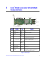
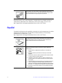
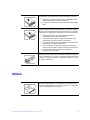
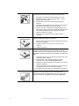
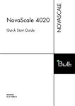
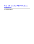
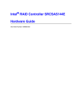
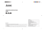
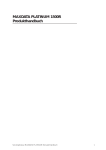
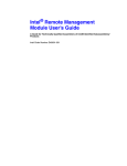
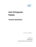
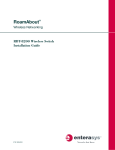
Intel® RAID Controller SRCSATAWB
Hardware User’s Guide
Intel Order Number: D92006-001
INFORMATION IN THIS DOCUMENT IS PROVIDED IN CONNECTION WITH INTEL(R)
PRODUCTS. NO LICENSE, EXPRESS OR IMPLIED, BY ESTOPPEL OR OTHERWISE, TO ANY
INTELLECTUAL PROPERTY RIGHTS IS GRANTED BY THIS DOCUMENT. EXCEPT AS
PROVIDED IN INTEL'S TERMS AND CONDITIONS OF SALE FOR SUCH PRODUCTS, INTEL
ASSUMES NO LIABILITY WHATSOEVER, AND INTEL DISCLAIMS ANY EXPRESS OR IMPLIED
WARRANTY, RELATING TO SALE AND/OR USE OF INTEL PRODUCTS INCLUDING LIABILITY
OR WARRANTIES RELATING TO FITNESS FOR A PARTICULAR PURPOSE,
MERCHANTABILITY, OR INFRINGEMENT OF ANY PATENT, COPYRIGHT OR OTHER
INTELLECTUAL PROPERTY RIGHT. Intel products are not intended for use in medical, life saving,
life sustaining applications. Intel may make changes to specifications and product descriptions at
any time, without notice.
Intel is a trademark or registered trademark of Intel Corporation or its subsidiaries in the United
States and other countries.
*Other names and brands may be claimed as the property of others.
Copyright © 2007 by Intel Corporation. Portions Copyright 2005-2007 by LSI Logic Corporation. All
rights reserved.
ii
Intel® RAID Controller SRCSATAWB Hardware User’s Guide
Preface
This is the primary hardware guide for the Intel® RAID Controller SRCSATAWB, which
can be used for SATA disk drives. It contains installation instructions and specifications.
For details on how to configure the storage adapters, and for an overview of the software
drivers, see the Software User’s Guide on the Resource CD.
Audience
This document assumes that you have some familiarity with RAID controllers and related
support devices. The people who benefit from this book are:
• Engineers who are designing a Intel® RAID Controller SRCSATAWB storage
adapter into a system.
• Anyone installing a Intel® RAID Controller SRCSATAWB storage adapter in their
RAID system.
Organization
This document includes the following chapters and appendixes:
• Chapter 1 provides a general overview of the Intel® RAID Controller
SRCSATAWB.
• Chapter 2 describes the procedures for installing the RAID controller.
• Chapter 3 provides the characteristics and technical specifications for the Intel®
RAID Controller SRCSATAWB.
• Appendix A explains drive roaming and how to do a drive migration.
Related Publication
The Software User’s Guide on the Resource CD that is included with the RAID controller.
Intel® RAID Controller SRCSATAWB Hardware User’s Guide
iii
iv
Intel® RAID Controller SRCSATAWB Hardware User’s Guide
Contents
Preface ........................................................................................................................ iii
Audience ............................................................................................................................... iii
Organization ......................................................................................................................... iii
Related Publication ............................................................................................................... iii
Chapter 1, Overview ................................................................................................... 1
Intel® RAID Controller SRCSATAWB .................................................................................... 1
Protocol Support ............................................................................................................ 1
Usability ......................................................................................................................... 2
SATA Features of the 1078 Controller .......................................................................... 4
Beep Codes ................................................................................................................... 5
Chapter 2, Intel® RAID Controller SRCSATAWB Hardware Installation ................ 6
Requirements ........................................................................................................................ 6
Install the RAID Controller ..................................................................................................... 6
Configure the RAID Controller ............................................................................................... 9
Replacing a Controller, Resolving a Config Mismatch ........................................................... 9
Chapter 3, Intel® RAID Controller SRCSATAWB Characteristics ........................ 10
Technical Specifications ......................................................................................................11
Array Performance Features ...............................................................................................12
Fault Tolerance ............................................................................................................12
Electrical Characteristics .............................................................................................13
Safety Characteristics ..................................................................................................13
A. Drive Roaming and Drive Migration Install ........................................................ 15
Drive Roaming .....................................................................................................................15
Drive Migration .....................................................................................................................16
B. Installation / Assembly Safety Instructions ....................................................... 17
English .................................................................................................................................19
Deutsch ................................................................................................................................20
Français ...............................................................................................................................22
Español ................................................................................................................................23
Italiano .................................................................................................................................24
C. Regulatory and Certification Information .......................................................... 26
Electromagnetic Compatibility Notices ................................................................................28
Intel® RAID Controller SRCSATAWB Hardware User’s Guide
v
1
Overview
The Intel® RAID Controller SRCSATAWB is a high-performance intelligent PCIExpress* SATA RAID controller that offers reliability, high performance, and faulttolerant disk subsystem management. This is an RAID solution meets the internal storage
needs of workgroup, department, or enterprise systems to use cost-effective SATA media.
As a third generation PCI Express storage controller, the Intel® RAID Controller
SRCSATAWB addresses the demand for increased data throughput and scalability
requirements across entry-level and midrange server platforms.
The controller can be connected to up to eight drives directly and allows the use of
expanders to connect to additional drives. See the ANSI SAS standard, version 1.0
specification for more information about the use of expanders.
SATA is a serial, point-to-point, device interface that uses simplified cabling, smaller
connectors, lower pin counts, and lower power requirements than parallel SCSI.
The optional Intel® RAID Smart Battery AXXRSBBU4 provides cached data protection
for the RAID controller, even during system failures.
Intel® RAID Controller SRCSATAWB
The Intel® RAID Controller SRCSATAWB is an intelligent low-profile RAID adapter
with an integrated LSI* 1078 RAID-On-Chip chipset, providing both a SATA controller
and a RAID engine. With 128 MB RAM built onto the board and eight independent ports
using two SFF-8087 mini multi-lane connectors, this controller supports up to 16
enterprise-class SATA devices and 64 logical drives. The PCI-Express* connector fits into
an x4 or x8 PCI-Express slot capable of 2.5 Gbps per lane over PCI Express* x4 with a
3.0 Gbps point to point transfer rate.
Protocol Support
• Serial ATA (SATA) protocol defined by the Serial ATA specification, version 1.0a.
• SATA II Protocol: Communication with other SATA II devices.
• Serial Management Protocol (SMP): Topology management information sharing
with expanders.
• Serial Tunneling Protocol (STP) support for SATAII through expander interfaces.
1
Intel® RAID Controller SRCSATAWB Hardware User’s Guide
Operating System Support
• Windows Server 2003*, Windows 2000* Enterprise Server, SP4 and Windows XP*.
• Red Hat* Enterprise Linux 3.0 and 4.0.
• SuSE* Linux Enterprise Server 9, SP1-3 and SLES 10.
The operating systems supported may not be supported by your server board. See the
tested operating system list for your server board at
http://support.intel.com/support/motherboards/server/. See also the tested hardware and
operating system list for the RAID Controller SRCSATAWB to make sure the RAID card
supports your operating system.
Usability
•
•
•
•
•
•
•
The card ships with both a standard and a low-profile bracket.
Small, thin cabling with serial point-to-point 3.0 Gbps data transfer rates.
Support for non-disk devices and mixed capacity drives.
Support for intelligent XOR RAID levels 0, 1, 5, 6, 10, 50, and 60.
Dedicated or global hot spare with auto rebuild if an array drive fails.
User defined stripe size per drive: 8, 16, 32, 64 (def), 128, 256, 512 KB or 1 GB.
Advanced Array configuration and Management Utilities provides:
— Online Capacity Expansion (OCE) adds space to existing drive or new drive.
See Appendix A for limitations on OCE and RAID migration.
— Online RAID level migration (upgrade of RAID mode, may require OCE).
— Drive migration.
— Drive roaming.
— No reboot necessary after expansion.
• Upgradeable Flash ROM interface.
• Allows for staggered spin up, hot-plug, and lower power consumption.
• User specified rebuild rate (percent of system resources to use from 0-100%).
Caution: Exceeding 50% rate may cause operating system errors due to waiting for
controller access.
• Background operating mode can be set for Rebuilds, Consistency Checks,
Initialization (auto restarting Consistency Check on redundant volumes); Migration,
OCE, and Patrol Read.
Intel® RAID Controller SRCSATAWB Hardware User’s Guide
2
Redundancy and Error Handling
•
•
•
•
•
In-band and out-of-band SES2.
Enclosure management support.
Activity and fault indicators per drive.
Drive coercion (auto-resizing to match existing disks).
Auto-detection of failed drives with transparent rebuild. There must be disk activity
(I/O to the drive) for a missing drive to be marked as failed.
• Auto-resume on reboot of initialization or rebuild (must be enabled before virtual
disk creation).
• Smart initialization automatically checks consistency of virtual disks if there are five
or more disks in a RAID 5 array, which optimizes performance by enabling readmodify-write mode. RAID 5 arrays of only three or four drives use Peer Read mode.
•
•
•
•
•
•
•
Dirty cache LED plus error reporting for cache write to disk.
Smart Technology predicts failures of drives and electronic components.
Patrol Read checks drives and maps bad sectors.
Commands are retried at least four times.
Firmware provides best effort to recognize an error and recover if possible.
Failures are logged from controller and drive firmware, and SMART monitor.
Failures are logged in NVRAM, viewable from OS Event Log, Intel® RAID Web
Console 2; CIM, LEDs, and via alarm.
• Multiple cache options allow configuration-specific performance optimization:
— Write-back. Faster because it does not wait for the disk but data will be lost if
power is lost.
— Write-through. Usually slower but ensures data is on the disk.
— Read Ahead. Predicts next read will be sequential and buffers this data into the
cache.
— Non Read Ahead. Always reads from the drive after determining exact location
of each read.
— Adaptive Read Ahead. Reads ahead and caches data only if doing sequential
reads.
— I/O setting. Determines whether read operations check the cache before reading
from disks.
✧ Cache I/O: Checks cache first, only reads disk if data is not in the cache.
✧ Direct I/O: Reads data directly from disk. (not cache)
3
Intel® RAID Controller SRCSATAWB Hardware User’s Guide
• Redundancy through:
— Configuration stored in nonvolatile RAM and on the drives (COD).
— Hot-swap support.
— Optional battery backup for cache memory. Controller provides fast or trickle
charges.
SATA Features of the 1078 Controller
• Provides eight independent phys, each supporting 3.0 Gbps SATA data transfers.
• Scalable interface that supports up to 16 physical devices and 64 logical devices via
expanders.
• Supports SSP to enable communication with other SATA devices.
• Supports SMP to communicate topology management information.
• Supports single PHY or wide ports consisting of 2, 3, or 4 PHY within one quad
port.
• Allows addressing of multiple SATA targets through an expander if using SATA 2.0compliant hard disk drives.
• Allows multiple initiators to address a single target (in a fail-over configuration)
through an expander.
Intel® RAID Controller SRCSATAWB Hardware User’s Guide
4
Online Capacity Expansion and RAID Level Migration Rules
•
•
•
•
Migration must occur to the same or larger capacity configuration.
Migration cannot occur if there is more than one virtual disk in a logical array.
Migration and OCE cannot be done on Spanned Arrays (RAID 10, 50, 60).
Migrations supported are : RAID 1 to RAID 0, RAID 5 to RAID 0, RAID 6 to RAID
0.
• With OCE migrations supported are RAID 0 to RAID 1, RAID 0 to RAID 5, RAID
1 to RAID 5.
Beep Codes
• Short beep, 1 second on, 1 second off. Array is degraded but no data lost.
• Long beep, 3 seconds on, 1 second off. Array has failed. Data has been lost.
• Short beep, 1 second on, 3 seconds off. Using hot spare in rebuild. Alarm will
continue during rebuild with a different sound at completion.
To disable the alarm, choose Disable Alarm. To enable alarm, choose Enable Alarm.
To disable alarm only until the next event or until next power cycle, choose Silence
Alarm.
5
Intel® RAID Controller SRCSATAWB Hardware User’s Guide
2
Intel® RAID Controller SRCSATAWB
Hardware Installation
Requirements
• The Intel® RAID Controller SRCSATAWB, with the provided cables.
• A host system with an available x4 or x8 PCI-Express* slot.
• The Resource CD, which contains drivers and documentation.
• SATA hard drives.
Note: Intel Corporation strongly recommends using an uninterruptible power supply (UPS).
Install the RAID Controller
1. Turn off the power to the system and all drives, enclosures, and system
components. Remove the power cord(s).
2. Follow the instructions that came with your server system to remove the server
cover.
3. If necessary, change the bracket on the RAID controller to fit the height of the
server system. See the following figure.
AF002212
Figure 1. Changing the Bracket
4. Install the RAID controller into an available server system x4 or x8 PCI-Express*
slot. See your server system documentation to locate an appropriate slot and for
instructions on installing an add-in card. See also the following figure.
Intel® RAID Controller SRCSATAWB Hardware User’s Guide
6
Figure 2. Installing the Intel® RAID Controller SRCSATAWB
5. For the first four drives, ports 0 - 3, connect one 4-port combined end of an internal
cables to the upper connector. If you are using more than four drives without using
an expander backplane, connect the second cable to the lower connector. See the
following figure.
Notes:
• To prevent throughput problems, use the cables provided or use the shortest possible
cable. Do not use cables longer than one meter. Decrease the maximum length by
one foot if using a backplane.
• Do not use cross-over cables.
• The cables are labeled with the word “SAS,” but only SATA drives are supported.
Do not attempt to install a SAS drive. Only connect to a SATA drive or to a
SAS/SATA backplane. The RAID Controller SRCSATAWB uses an advanced
software stack that allows connections to SATA drives either directly or via SAS or
SATA backplanes with or without expanders.
• Route the cables carefully. Check that controller and cables are all properly
attached.
7
Intel® RAID Controller SRCSATAWB Hardware User’s Guide
AF002211
Figure 3. Connecting Cables between the RAID Controller and Drives/Backplane
6. Install the server system cover and connect the power cords. See your server system
documentation for instructions.
Intel® RAID Controller SRCSATAWB Hardware User’s Guide
8
Configure the RAID Controller
1. Turn on the system power and listen to be sure that the SATA devices power up
before or at the same time as the system.
2. During the boot, a BIOS message displays to state the keys to press to enter the
Intel® RAID BIOS Console 2, such as
Press <CTRL><G> to run BIOS Console 2.
This message times out after several seconds. If you miss it, you need to restart the
system.
After you press the keys to enter the Intel® RAID BIOS Console 2 software, the
firmware takes several seconds to initialize and then display the RAID Controller
SRCSATAWB number and firmware version. The numbering of the RAID
controller follows the PCI slot scanning order used by the server board.
3. See the Intel® RAID Controller SRCSATAWB Quick Start User’s Guide and the
Software User's Guide for instructions to configure the RAID controller and to
install the operating system drivers.
Replacing a Controller, Resolving a Config Mismatch
To replace the RAID controller, see your server system documentation for instructions to
remove and then install an add-in adapter.
If the newly installed RAID controller was previously configured, a message displays
during POST, stating that there is a configuration mismatch because the configuration data
in the NVRAM differs from that in the hard drives. Use these steps to resolve the
mismatch:
1. Press <Ctrl> + <G> when prompted during boot up to access the BIOS
Configuration Utility.
2. Select Configure > View/Add Configuration to see the NVRAM and drive
configurations.
3. Since the drives contain the correct configuration, use configuration from the disks.
4. Press <Esc> and select YES to update the NVRAM.
5. Exit and reboot.
9
Intel® RAID Controller SRCSATAWB Hardware User’s Guide
3
Intel® RAID Controller SRCSATAWB
Characteristics
J7
Embedded RAM
J1 J2
J3 Speaker
J6
J5
J8,
ports 3 - 0
J9,
ports 7 - 4
J10
LSI* 1078 ROC
AF002341
Battery Mount Points
Jumper
Description
Type
Comments
J1
Dirty cache LED
header
2-pin
header
Provides signal to indicate cache needs to write
data.
J2
On-board BIOS
enable
2-pin
jumper
Default is for no jumper
J3
Serial UART port
4-pin
header
Debug use only
J5
Drive fault LEDs
8x2 header
LED signal for drive fault per port for eight ports
(not available through expander)
J6
I2C header (SES2)
3-pin
header
Enclosure management support (usually a nonexpander hot-swap backplane)
J7
Battery connector
Daughter
card
connector
Connector used for optional battery backup pack
J8
Internal SAS/SATA
port connector
SFF8087
For ports 0 - 3
J9
Internal SAS/SATA
port connector
SFF8087
For ports 4 - 7
J10
Firmware recovery
jumper
2-pin
jumper
This jumper needed only for flashes if the firmware
is corrupted. The card does not function as a
controller if this jumper is in place.
Figure 4. Card Layout
s
Intel® RAID Controller SRCSATAWB Hardware User’s Guide
10
Technical Specifications
Intel® RAID Controller SRCSATAWB
Specification
11
Processor
LSI* 1078 Integrated RAID on Chip 500 MHz
Operating foltage
+3.3 V, +12 V
Card size
Low profile, extended half-length (7.71-inch x 2.536-inch)
Array interface to host
PCI Express* Rev 1.0A, x4 lane width 2.5 Gbps
SATA bus speed
3 Gbps per port, point-to-point
Serial port
3-pin RS232-compatible connector for debug use only
SATA controller
LSI 1078
SATA ports
2x4 internal ports, 16 devices per port with expanders
Physical and virtual drive
support
16 drives per controller; 32 virtual drives per controller; 16 hot
spares per controller (global and/or dedicated)
Cache
128 MBs DDR2 667 MHz SDRAM, optional battery backup
Firmware
4 M in reflashable flash ROM
Compatible devices
2.5-inch and 3.5-inch SATA 3.0 drives; non disk devices
including expanders and drives of mixed capacity.
Cabling
Small, thin cables do not restrict airflow; Shared connectors for
multiple drives
Redundant configuration
32 Kb NVRAM and config-on-disk (COD)
Enclosure management
In-band and out-of-band SES2
Enclosure support
Assumes one SEP per enclosure
Array support
128 arrays per controller; 16 drives per array; 16 virtual drives
per array.
Intel® RAID Controller SRCSATAWB Hardware User’s Guide
Array Performance Features
Host data transfer rate
2.5 Gigabit/s per PCI Express* lane
Drive data transfer rate
3 Gigabit/s per lane
Maximum scatter / gather
26 elements
Maximum size of I/O requests
6.4 Mbytes in 64 Kbyte stripes
Max queue tags per drive
As many as the drive can accept
Stripe sizes
8, 16, 32, 64, 128, 256, 512 or 1024 KB
Max concurrent commands
255
Support for multiple initiators
Yes
Performance
Native command queuing
Flexibility
Drive migration, RAID level migration, Drive Roaming, Online
Capacity Expansion - without reboot
Background services
Rebuild, Consistency Check, Migration, OCE, and Patrol Read
Cache options
Write-back or Write-through Read Ahead, Adaptive Read
Ahead, NonRead Ahead, Cache I/O or Direct I/O
Fault Tolerance
Self Monitoring Analysis and
Reporting Technology (SMART)
support
Detects up to 70% of predictable disk drive failures and
monitors the internal performance of all motors, heads,
and drive electronics.
Optional Battery Backup
Intel® RAID Smart Battery AXXRSBBU4 cache backup.
Up to 72 hours of data retention. “Gas Gauge".
Drive Replacement
Auto detection of failure, hot plug, hot swap.
Drive Rebuild Using Hot Spares
Automatic at fail: Dedicated per Array; Global for any
array; Auto-resume of initialization or rebuild on reboot
Error Checking and Indication
Parity generation and checking, automatic consistency
checking; patrol reads; activity and fault LEDs, alarm;
multiple retries; logs in NVRAM, event log, CIM, Smart,
Intel® RAID Web Console 2
Intel® RAID Controller SRCSATAWB Hardware User’s Guide
12
Electrical Characteristics
PCI +12 V
1.0-1.81A
PCI +3.3 Aux
30mA
PCI +3.3 V
330mA
Temperatures
Other
0C to 40C with battery.
0 to 50C without battery
Non-operating, no
battery -30C to +80C
Airflow > 200 LFPM relative
humidity non-condensing:
5%-90%. With battery 20-80%
10-90% condensing
Safety Characteristics
The Intel® RAID Controller SRCSATAWB meets or exceeds the requirements of UL
flammability rating 94 V0. Each bare board is marked with the supplier name or
trademark, type, and UL flammability rating. For the boards installed in a PCI bus slot, all
voltages are lower than the SELV 42.4 V limit.
13
Intel® RAID Controller SRCSATAWB Hardware User’s Guide
Intel® RAID Controller SRCSATAWB Hardware User’s Guide
14
Appendix A:
Drive Roaming and Drive
Migration Install
Drive Roaming
Drive roaming occurs when the hard drives are changed to different ports on the same
controller. When the drives are placed on different ports, the controller detects the RAID
configuration from the configuration data on the drives.
Note: If you move a drive that is currently being rebuilt, the rebuild operation will restart, not
resume.
To use drive roaming:
1. Turn off the power to the system and all drives, enclosures, and system
components. Remove the power cord(s).
2. Follow the instructions that came with your server system to remove the server
cover.
3. Move the drives to different positions on the backplane to change the targets. See
your server documentation for instructions to install and remove drives.
4. Determine the target requirements.
5. Make sure the drives are inserted properly.
6. Follow the instructions that came with your server system to remove the server
cover.
7. Plug in and power on the system.
The controller detects the RAID configuration from the configuration data on the drives
(COD).
15
Intel® RAID Controller SRCSATAWB Hardware User’s Guide
Drive Migration
Drive migration moves a configured set of hard drives from one controller to another. The
drives must remain on the same port and be reinstalled in the same order as in the original
configuration. The controller to which you migrate the drives cannot have an existing
configuration.
Note: Only complete configurations can be migrated; individual virtual disks cannot be
migrated. Drive roaming and drive migration cannot be supported at the same time.
To migrate drives:
1. Clear the configuration on the system to which you migrate the drives. This
prevents a configuration data mismatch between the hard drives and the NVRAM.
2. Turn off the power to the system and all drives, enclosures, and system
components. Remove the power cord(s).
3. Follow the instructions that came with your server system to remove the server
cover.
4. Disconnect the cables from the drives to be migrated.
5. Remove the hard drives from the first system and install them into the second
system. See your server documentation for instructions to install and remove
drives.
6. Connect the data cables to the hard drives in the second system in the same order as
they were connected in the first system. Make sure all the cables meet
specifications.
7. Determine the drive target requirements.
8. Make sure all cables are properly attached and the RAID controller is properly
installed.
9. Follow the instructions that came with your server system to remove the server
cover.
10. Plug in and power on the system.
When you start the system, the controller detects the RAID configuration from the
configuration data on the drives.
Intel® RAID Controller SRCSATAWB Hardware User’s Guide
16
Appendix B:
Installation / Assembly
Safety Instructions
As you use your computer system, observe these safety guidelines:
• Do not operate your computer system with any cover(s) (such as computer covers,
bezels, filler brackets, and front-panel inserts) removed:
• To help avoid damaging your computer, be sure the voltage selection switch on the
power supply is set to match the alternating current (AC) power available at your
location.
• To help avoid possible damage to the server board, wait five seconds after turning
off the system before removing a component from the server board or disconnecting
a peripheral device from the computer.
• To help prevent electric shock, plug the computer and peripheral power cables into
properly grounded power sources. These cables are equipped with 3-prong plugs to
ensure proper grounding. Do not use adapter plugs or remove the grounding prong
from a cable. If you must use an extension cable, use a 3-wire cable with properly
grounded plugs.
• To help protect your computer system from sudden, transient increases and
decreases in electrical power, use a surge suppressor, line conditioner, or
uninterruptible power supply.
• Be sure nothing rests on your computer system's cables and that the cables are not
located where they can be stepped on or tripped over.
• Do not spill food or liquids on your computer. If the computer gets wet, consult the
documentation that came with it.
• Do not push any objects into the openings of your computer. Doing so can cause fire
or electric shock by shorting out interior components.
• Keep your computer away from radiators and heat sources. Also, do not block
cooling vents. Avoid placing loose papers underneath your computer; do not place
your computer in a closed-in wall unit or on a rug.
When working inside your computer:
• Do not attempt to service the computer system yourself, except as explained in this
guide and elsewhere in Intel documentation. Always follow installation and service
instructions closely.
• Turn off your computer and any peripherals.
• Disconnect your computer and peripherals from their power sources. Also
disconnect any telephone or telecommunications lines from the computer.
• Doing so reduces the potential for personal injury or shock.
17
Additional safety guidelines:
• When you disconnect a cable, pull on its connector or on its strain-relief loop, not on
the cable itself. Some cables have a connector with locking tabs; if you are
disconnecting this type of cable, press in on the locking tabs before disconnect the
cable. As you pull connectors apart, keep them evenly aligned to avoid bending any
connector pins. Also, before you connect a cable, make sure both connectors are
correctly oriented and aligned.
• Handle components and cards with care. Don't touch the components or contacts on
a card. Hold a card by its edges or by its metal mounting bracket. Hold a component
such as a microprocessor chip by its edges, not by its pins.
Protecting against electrostatic discharge
• Static electricity can harm delicate components inside your computer. To prevent
static damage, discharge static electricity from your body before you touch any of
your computer's electronic components, such as the microprocessor. You can do so
by touching an unpainted metal surface, such as the metal around the card-slot
openings at the back of the computer.
• As you continue to work inside the computer, periodically touch an unpainted metal
surface to remove any static charge your body may have accumulated. In addition to
the preceding precautions, you can also take the following steps to prevent damage
from electrostatic discharge (ESD):
• When unpacking a static-sensitive component from its shipping carton, do not
remove the component from the antistatic packing material until you are ready to
install the component in your computer. Just before unwrapping the antistatic
packaging, be sure to discharge static electricity from your body.
• When transporting a sensitive component, first place it in an antistatic container or
packaging.
• Handle all sensitive components in a static-safe area. If possible, use antistatic floor
pads and workbench pads.
Intel® RAID Controller SRCSATAWB Hardware User’s Guide
18
English
Read all caution and safety statements in this document before performing any of the
instructions. See also Intel Server Boards and Server Chassis Safety Information on the
Resource CD and/or at http:\\support.intel.com\support\motherboards\server\sb\cs010770.htm.
The power button on the system does not turn off system AC power.
To remove AC power from the system, you must unplug each AC
power cord from the wall outlet or power supply.
The power cord(s) is considered the disconnect device to the main
(AC) power. The socket outlet that the system plugs into shall be
installed near the equipment and shall be easily accessible.
SAFETY STEPS: Whenever you remove the chassis covers to
access the inside of the system, follow these steps:
1. Turn off all peripheral devices connected to the system.
2. Turn off the system by pressing the power button.
3. Unplug all AC power cords from the system or from wall
outlets.
4. Label and disconnect all cables connected to I/O connectors
or ports on the back of the system.
5. Provide some electrostatic discharge (ESD) protection by
wearing an antistatic wrist strap attached to chassis ground of
the system-any unpainted metal surface-when handling
components.
6. Do not operate the system with the chassis covers removed.
After you have completed the six SAFETY steps above, you can
remove the system covers. To do this:
1. Unlock and remove the padlock from the back of the system if
a padlock has been installed.
2. Remove and save all screws from the covers.
3. Remove the cover(s).
For proper cooling and airflow, always reinstall the chassis covers
before turning on the system. Operating the system without the
covers in place can damage system parts. To install the covers:
1. Check first to make sure you have not left loose tools or parts
inside the system.
2. Check that cables, add-in cards, and other components are
properly installed.
3. Attach the covers to the chassis with the screws removed
earlier, and tighten them firmly.
4. Insert and lock the padlock to the system to prevent
unauthorized access inside the system.
5. Connect all external cables and the AC power cord(s) to the
system.
19
Intel® RAID Controller SRCSATAWB Hardware User’s Guide
A microprocessor and heat sink may be hot if the system has been
running. Also, there may be sharp pins and edges on some board
and chassis parts. Contact should be made with care. Consider
wearing protective gloves.
Deutsch
Lesen Sie zunŠchst sŠmtliche Warn- und Sicherheitshinweise in diesem
Dokument, bevor Sie eine der Anweisungen ausfŸhren. Beachten Sie hierzu auch
die Sicherheitshinweise zu Intel-Serverplatinen und -ServergehŠusen auf der
Ressourcen-CD oder unter
http:\\support.intel.com\support\motherboards\server\sb\cs-010770.htm.
Der Wechselstrom des Systems wird durch den Ein-/Aus-Schalter
für Gleichstrom nicht ausgeschaltet. Ziehen Sie jedes
Wechselstrom-Netzkabel aus der Steckdose bzw. dem Netzgerät,
um den Stromanschluß des Systems zu unterbrechen.
SICHERHEISMASSNAHMEN: Immer wenn Sie die
Gehäuseabdeckung abnehmen um an das Systeminnere zu
gelangen, sollten Sie folgende Schritte beachten:
1. Schalten Sie alle an Ihr System angeschlossenen
Peripheriegeräte aus.
2. Schalten Sie das System mit dem Hauptschalter aus.
3. Ziehen Sie den Stromanschlußstecker Ihres Systems aus der
Steckdose.
4. Auf der Rückseite des Systems beschriften und ziehen Sie
alle Anschlußkabel von den I/O Anschlüssen oder Ports ab.
5. Tragen Sie ein geerdetes Antistatik Gelenkband, um
elektrostatische Ladungen (ESD) über blanke Metallstellen
bei der Handhabung der Komponenten zu vermeiden.
6. Schalten Sie das System niemals ohne ordnungsgemäß
montiertes Gehäuse ein.
Intel® RAID Controller SRCSATAWB Hardware User’s Guide
20
SICHERHEISMASSNAHMEN: Immer wenn Sie die
Gehäuseabdeckung abnehmen um an das Systeminnere zu
gelangen, sollten Sie folgende Schritte beachten:
1. Schalten Sie alle an Ihr System angeschlossenen
Peripheriegeräte aus.
2. Schalten Sie das System mit dem Hauptschalter aus.
3. Ziehen Sie den Stromanschlußstecker Ihres Systems aus der
Steckdose.
4. Auf der Rückseite des Systems beschriften und ziehen Sie
alle Anschlußkabel von den I/O Anschlüssen oder Ports ab.
5. Tragen Sie ein geerdetes Antistatik Gelenkband, um
elektrostatische Ladungen (ESD) über blanke Metallstellen
bei der Handhabung der Komponenten zu vermeiden.
6. Schalten Sie das System niemals ohne ordnungsgemäß
montiertes Gehäuse ein.
Zur ordnungsgemäßen Kühlung und Lüftung muß die
Gehäuseabdeckung immer wieder vor dem Einschalten installiert
werden. Ein Betrieb des Systems ohne angebrachte Abdeckung
kann Ihrem System oder Teile darin beschädigen. Um die
Abdeckung wieder anzubringen:
1. Vergewissern Sie sich, daß Sie keine Werkzeuge oder Teile
im Innern des Systems zurückgelassen haben.
2. Überprüfen Sie alle Kabel, Zusatzkarten und andere
Komponenten auf ordnungsgemäßen Sitz und Installation.
3. Bringen Sie die Abdeckungen wieder am Gehäuse an, indem
Sie die zuvor gelösten Schrauben wieder anbringen. Ziehen
Sie diese gut an.
4. Bringen Sie die Verschlußeinrichtung (Padlock) wieder an und
schließen Sie diese, um ein unerlaubtes Öffnen des Systems
zu verhindern.
5. Schließen Sie alle externen Kabel und den AC
Stromanschlußstecker Ihres Systems wieder an.
Der Mikroprozessor und der Kühler sind möglicherweise erhitzt,
wenn das System in Betrieb ist. Außerdem können einige Platinen
und Gehäuseteile scharfe Spitzen und Kanten aufweisen. Arbeiten
an Platinen und Gehäuse sollten vorsichtig ausgeführt werden. Sie
sollten Schutzhandschuhe tragen.
21
Intel® RAID Controller SRCSATAWB Hardware User’s Guide
Français
Lisez attention toutes les consignes de sŽcurité et les mises en garde indiquŽes dans ce
Notez que le commutateur CC de mise sous tension /hors tension
du panneau avant n'éteint pas l'alimentation CA du système. Pour
mettre le système hors tension, vous devez débrancher chaque
câble d'alimentation de sa prise.
CONSIGNES DE SÉCURITÉ -Lorsque vous ouvrez le boîtier pour
accéder à l'intérieur du système, suivez les consignes suivantes:
1. Mettez hors tension tous les périphériques connectés au
système.
2. Mettez le système hors tension en mettant l'interrupteur
général en position OFF (bouton-poussoir).
3. Débranchez tous les cordons d'alimentation c.a. du système
et des prises murales.
4. Identifiez et débranchez tous les câbles reliés aux
connecteurs d'E-S ou aux accès derrière le système.
5. Pour prévenir les décharges électrostatiques lorsque vous
touchez aux composants, portez une bande antistatique pour
poignet et reliez-la à la masse du système (toute surface
métallique non peinte du boîtier).
6. Ne faites pas fonctionner le système tandis que le boîtier est
ouvert.
Une fois TOUTES les étapes précédentes accomplies, vous pouvez
retirer les panneaux du système. Procédez comme suit:
1. Si un cadenas a été installé sur à l'arrière du système,
déverrouillez-le et retirez-le.
2. Retirez toutes les vis des panneaux et mettez-les dans un
endroit sûr.
3. Retirez les panneaux.
Afin de permettre le refroidissement et l'aération du système,
réinstallez toujours les panneaux du boîtier avant de mettre le
système sous tension. Le fonctionnement du système en l'absence
des panneaux risque d'endommager ses pièces. Pour installer les
panneaux, procédez comme suit:
1. Assurez-vous de ne pas avoir oublié d'outils ou de pièces
démontées dans le système.
2. Assurez-vous que les câbles, les cartes d'extension et les
autres composants sont bien installés.
3. Revissez solidement les panneaux du boîtier avec les vis
retirées plus tôt.
4. Remettez le cadenas en place et verrouillez-le afin de
prévenir tout accès non autorisé à l'intérieur du système.
5. Rebranchez tous les cordons d'alimentation c. a. et câbles
externes au système.
Intel® RAID Controller SRCSATAWB Hardware User’s Guide
22
Le microprocesseur et le dissipateur de chaleur peuvent être chauds
si le système a été sous tension. Faites également attention aux
broches aiguës des cartes et aux bords tranchants du capot. Nous
vous recommandons l'usage de gants de protection.
document avant de suivre toute instruction. Consultez Intel Server Boards and Server
Chassis Safety Information sur le CD Resource CD ou bien rendez-vous sur le site
http:\\support.intel.com\support\motherboards\server\sb\cs-010770.htm.
Español
Lea todas las declaraciones de seguridad y precaucion de este documento antes de realizar
cualquiera de las instrucciones. Vea Intel Server Boards and Server Chassis Safety
Information en el CD Resource y/o en
http:\\support.intel.com\support\motherboards\server\sb\cs-010770.htm
Nótese que el interruptor activado / desactivado en el panel frontal
no desconecta la corriente alterna del sistema. Para desconectarla,
deberá desenchufar todos los cables de corriente alterna de la
pared o desconectar la fuente de alimentación.
INSTRUCCIONES DE SEGURIDAD: Cuando extraiga la tapa del
chasis para acceder al interior del sistema, siga las siguientes
instrucciones:
1. Apague todos los dispositivos periféricos conectados al
sistema.
2. Apague el sistema presionando el interruptor encendido /
apagado.
3. Desconecte todos los cables de alimentación CA del sistema
o de las tomas de corriente alterna.
4. Identifique y desconecte todos los cables enchufados a los
conectores E/S o a los puertos situados en la parte posterior
del sistema.
5. Cuando manipule los componentes, es importante protegerse
contra la descarga electrostática (ESD). Puede hacerlo si
utiliza una muñequera antiestática sujetada a la toma de tierra
del chasis - o a cualquier tipo de superficie de metal sin pintar.
6. No ponga en marcha el sistema si se han extraído las tapas
del chasis.
23
Intel® RAID Controller SRCSATAWB Hardware User’s Guide
Después de completar las seis instrucciones de SEGURIDAD
mencionadas, ya puede extraer las tapas del sistema. Para ello:
1. Desbloquee y extraiga el bloqueo de seguridad de la parte
posterior del sistema, si se ha instalado uno.
2. Extraiga y guarde todos los tornillos de las tapas.Extraiga las
tapas.
Para obtener un enfriamiento y un flujo de aire adecuados, reinstale
siempre las tapas del chasis antes de poner en marcha el sistema.
Si pone en funcionamiento el sistema sin las tapas bien colocadas
puede dañar los componentes del sistema. Para instalar las tapas:
1. Asegúrese primero de no haber dejado herramientas o
componentes sueltos dentro del sistema.
2. Compruebe que los cables, las placas adicionales y otros
componentes se hayan instalado correctamente.
3. Incorpore las tapas al chasis mediante los tornillos extraídos
anteriormente, tensándolos firmemente.
4. Inserte el bloqueo de seguridad en el sistema y bloquéelo
para impedir que pueda accederse al mismo sin autorización.
5. Conecte todos los cables externos y los cables de
alimentación CA al sistema.
Si el sistema ha estado en funcionamiento, el microprocesador y el
disipador de calor pueden estar aún calientes. También conviene
tener en cuenta que en el chasis o en el tablero puede haber piezas
cortantes o punzantes. Por ello, se recomienda precaución y el uso
de guantes protectores.
Italiano
L'interruttore attivato / disattivato nel pannello anteriore non
interrompe l'alimentazione in c.a. del sistema. Per interromperla, è
necessario scollegare tutti i cavi di alimentazione in c.a. dalle prese
a muro o dall'alimentazione di corrente.
Intel® RAID Controller SRCSATAWB Hardware User’s Guide
24
PASSI DI SICUREZZA: Qualora si rimuovano le coperture del telaio
per accedere all'interno del sistema, seguire i seguenti passi:
1. Spegnere tutti i dispositivi periferici collegati al sistema.
2. Spegnere il sistema, usando il pulsante spento / acceso
dell'interruttore del sistema.
3. Togliere tutte le spine dei cavi del sistema dalle prese
elettriche.
4. Identificare e sconnettere tutti i cavi attaccati ai collegamenti
I/O od alle prese installate sul retro del sistema.
5. Qualora si tocchino i componenti, proteggersi dallo scarico
elettrostatico (SES), portando un cinghia anti-statica da polso
che è attaccata alla presa a terra del telaio del sistema qualsiasi superficie non dipinta - .
6. Non far operare il sistema quando il telaio è senza le
coperture.
Dopo aver seguito i sei passi di SICUREZZA sopracitati, togliere le
coperture del telaio del sistema come seque:
1. Aprire e rimuovere il lucchetto dal retro del sistema qualora ve
ne fosse uno installato.
2. Togliere e mettere in un posto sicuro tutte le viti delle
coperture.
3. Togliere le coperture.
Per il giusto flusso dell'aria e raffreddamento del sistema, rimettere
sempre le coperture del telaio prima di riaccendere il sistema.
Operare il sistema senza le coperture al loro proprio posto potrebbe
danneggiare i componenti del sistema. Per rimettere le coperture del
telaio:
1. Controllare prima che non si siano lasciati degli attrezzi o dei
componenti dentro il sistema.
2. Controllare che i cavi, dei supporti aggiuntivi ed altri
componenti siano stati installati appropriatamente.
3. Attaccare le coperture al telaio con le viti tolte in precedenza e
avvitarle strettamente.
4. Inserire e chiudere a chiave il lucchetto sul retro del sistema
per impedire l'accesso non autorizzato al sistema.
5. Ricollegare tutti i cavi esterni e le prolunghe AC del sistema.
Se il sistema è stato a lungo in funzione, il microprocessore e il
dissipatore di calore potrebbero essere surriscaldati. Fare
attenzione alla presenza di piedini appuntiti e parti taglienti sulle
schede e sul telaio. È consigliabile l'uso di guanti di protezione.
25
Intel® RAID Controller SRCSATAWB Hardware User’s Guide
Appendix C:
Regulatory and Certification
Information
This RAID Controller Card complies with the following safety and electromagnetic
compatibility (EMC) regulations.
Product Safety Compliance
• UL 1950 - CSA 950 (US/Canada)
• EN 60 950 (European Union)
• IEC60 950 (International)
• CE - Low Voltage Directive (73/23/EEC) (European Union)
Product EMC Compliance - Class B
•
•
•
•
•
•
•
•
•
FCC / ICES-003 (USA/Canada)
CISPR 22 (International)
EN55022 (Europe)
EN55024 (Europe)
CE - EMC Directive 89/336/EEC (Europe)
VCCI (Japan)
AS/NZS 3548 (Australia / New Zealand)
BSMI CNS13438 (Taiwan)
RRL, MIC Notice No. 1997-41 (EMC) & 1997-42 (EMI) (Korea)
Product Regulatory Compliance Markings
The RAID Controller Card is marked with the following compliance markings.
Some marking information may be provided on the packaging and/or in the product
documentation due to limited marking space on the product.
•
•
•
•
•
•
ETL NRTL Mark (US/Canada)
FCC Mark (US)
ICES-003 (Canada)
CE Mark (Europe)
VCCI Mark (Japan)
MIC Mark (Korea)
Intel® RAID Controller SRCSATAWB Hardware User’s Guide
26
• BSMI DOC Mark (Taiwan)
• ACS C-Tick Mark (Australia)
Regulatory Compliance
27
Country
Marking
UL Listing Marks
USA/Canada
ETL (NRTL) Mark
USA/Canada
CE Mark
Europe
FCC Marking (Class A)
USA
FCC Marking (Class B)
USA
EMC Marking (Class A)
Canada
CANADA ICES-003 CLASS A
CANADA NMB-003 CLASSE A
EMC Marking (Class B)
Canada
CANADA ICES-003 CLASS B
CANADA NMB-003 CLASSE B
VCCI Marking (Class A)
Japan
VCCI Marking (Class B)
Japan
This device complies with Part 15 of the
FCC Rules. Operation of this device is
subject to the following two conditions:
(1) This device may not cause harmful
interference, and
(2) This device must accept any interference
received, including interference that may
cause undesired operation.
Intel® RAID Controller SRCSATAWB Hardware User’s Guide
Regulatory Compliance
Country
BSMI Marking (Class A or
B) and Class A EMC
Warning
Taiwan
RRL MIC Mark
Korea
C-Tick Mark
Australia
Marking
Electromagnetic Compatibility Notices
FCC Verification Statement (USA) :
This device complies with Part 15 of the FCC Rules. Operation is subject to the
following two conditions: (1) This device may not cause harmful interference, and
(2) this device must accept any interference received, including interference that
may cause undesired operation.
Intel Corporation
5200 N.E. Elam Young Parkway
Hillsboro, OR 97124-6497
Phone: 1-800-628-8686
This equipment has been tested and found to comply with the limits for a Class B
digital device, pursuant to Part 15 of the FCC Rules. These limits are designed to
provide reasonable protection against harmful interference in a residential
installation. This equipment generates, uses, and can radiate radio frequency energy
and, if not installed and used in accordance with the instructions, may cause harmful
interference to radio communications. However, there is no guarantee that
interference will not occur in a particular installation. If this equipment does cause
harmful interference to radio or television reception, which can be determined by
turning the equipment off and on, the user is encouraged to try to correct the
interference by one or more of the following measures:
• Reorient or relocate the receiving antenna.
• Increase the separation between the equipment and the receiver.
Intel® RAID Controller SRCSATAWB Hardware User’s Guide
28
• Connect the equipment into an outlet on a circuit different from that to which
the receiver is connected.
• Consult the dealer or an experienced radio/TV technician for help.
Intel is not responsible for any radio or television interference caused by
unauthorized modification of this equipment for substitution or attachment of
connecting cables and equipment other than those specified by Intel. The correction
of interferences caused by such unauthorized modification, substitution, or
attachment will be the responsibility of the user.
This RAID Controller has been tested to comply with FCC standards for home or
office use.
• ICES-003 (Canada) This digital apparatus does not exceed the Class B limits
for radio noise emissions from digital apparatus set out in the interferencecausing equipment standard entitled "Digital Apparatus," ICES-003 of the
Canadian Department of Communications.
Cet appareil numŽrique respecte les limites bruits radioŽlectriques applicables
aux appareils numŽriques de Classe Aprescrites dans la norme sur le matŽriel
brouilleur: "Appareils NumŽriques", NMB-003 ŽdictŽe par le Ministre
Canadien des Communictations.
• Europe (CE Declaration of Conformity) This product has been tested in
accordance too, and complies with the Low Voltage Directive (73/23/EEC)
and EMC Directive (89/336/EEC). The product has been marked with the CE
Mark to illustrate its compliance.
• RRL (Korea): Type of Equipment (Model Name): Model name on product
— Certification No.: On RRL certificate. Obtain certificate from local Intel
representative
— Name of Certification Recipient: LSI Logic Corporation
— Date of Manufacturer: Refer to date code on product
— Manuation: LSI Logic Corporation Manufacturer/Nation / Refer to
country of origin marked on product
29
Intel® RAID Controller SRCSATAWB Hardware User’s Guide