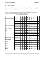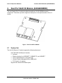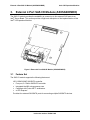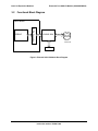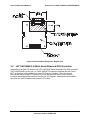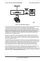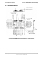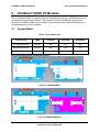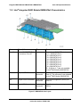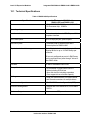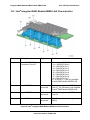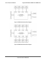
1
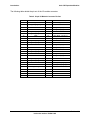
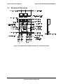
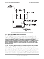
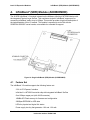
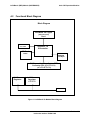
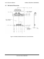
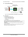
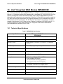
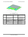
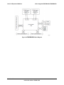
Intel® I/O Expansion Modules Hardware Specification Intel order number: D44901-008 Revision 1.2 September 2010 Enterprise Platforms and Services Division Intel® I/O Expansion Modules Revision History Revision History Date March 2009 Revision Number 1.0 Modifications Initial Release. November 2009 1.1 Added AXXIBQDRIOMOD. September 2010 1.2 Added new SAS modules and IB QDR modules. Disclaimers Information in this document is provided in connection with Intel® products. No license, express or implied, by estoppel or otherwise, to any intellectual property rights is granted by this document. Except as provided in Intel's Terms and Conditions of Sale for such products, Intel assumes no liability whatsoever, and Intel disclaims any express or implied warranty, relating to sale and/or use of Intel products including liability or warranties relating to fitness for a particular purpose, merchantability, or infringement of any patent, copyright or other intellectual property right. Intel products are not intended for use in medical, life saving, or life sustaining applications. Intel may make changes to specifications and product descriptions at any time, without notice. Designers must not rely on the absence or characteristics of any features or instructions marked "reserved" or "undefined." Intel reserves these for future definition and shall have no responsibility whatsoever for conflicts or incompatibilities arising from future changes to them. This document contains information on products in the design phase of development. Do not finalize a design with this information. Revised information will be published when the product is available. Verify with your local sales office that you have the latest datasheet before finalizing a design. The Intel® I/O Expansion Modules may contain design defects or errors known as errata which may cause the product to deviate from published specifications. Current characterized errata are available on request. Intel Corporation server baseboards contain a number of high-density VLSI and power delivery components that need adequate airflow to cool. Intel’s own chassis are designed and tested to meet the intended thermal requirements of these components when the fully integrated system is used together. It is the responsibility of the system integrator that chooses not to use Intel developed server building blocks to consult vendor datasheets and operating parameters to determine the amount of air flow required for their specific application and environmental conditions. Intel Corporation cannot be held responsible if components fail or the server board does not operate correctly when used outside any of their published operating or non-operating limits. Intel and Xeon are trademarks or registered trademarks of Intel Corporation. *Other brands and names may be claimed as the property of others. Copyright © Intel Corporation 2010. Revision 1.2 ii Intel order number: D44901-008 Intel® I/O Expansion Modules Table of Contents Table of Contents 1. Introduction .......................................................................................................................... 1 2. Dual Port GbE I/O Module (AXXGBIOMOD) ....................................................................... 3 2.1 Feature Set .............................................................................................................. 3 2.2 Functional Block Diagram ........................................................................................ 4 2.3 Mechanical Dimensions ........................................................................................... 5 2.4 Intel® 82571EB Gb Ethernet Controller.................................................................... 6 2.5 EEPROM ................................................................................................................. 7 2.6 PCI Express* x4 Connector ..................................................................................... 7 2.7 Ethernet Magjack ..................................................................................................... 7 3. External 4 Port SAS I/O Module (AXXSASIOMOD) ............................................................ 8 3.1 Feature Set .............................................................................................................. 8 3.2 Functional Block Diagram ........................................................................................ 9 3.3 Mechanical Dimensions ......................................................................................... 10 3.4 LSI* SAS1064E 3.0 Gbit/s Serial Attached SCSI Controller .................................. 11 3.4.1 Features of the LSI* SAS1064E ............................................................................ 13 3.5 External Flash Memory .......................................................................................... 13 3.6 PCI Express* x4 Connector ................................................................................... 13 3.7 External 4 SAS Connector .................................................................................... 13 4. InfiniBand* (SDR) Module (AXXIBIOMOD) ....................................................................... 15 4.1 Feature Set ............................................................................................................ 15 4.2 Functional Block Diagram ...................................................................................... 16 4.3 Mechanical Dimensions ......................................................................................... 17 4.4 LED Functionality ................................................................................................... 18 4.5 PCI Express* x4 Connector ................................................................................... 19 4.6 External Connector ................................................................................................ 19 5. Internal 4-port LSI 1064e SAS I/O Module (AXX4SASMOD) ........................................... 20 5.1 Major Component Diagram .................................................................................... 20 5.2 Functional Block Diagram ...................................................................................... 21 5.3 Feature Set ............................................................................................................ 21 5.4 Mechanical Drawings ............................................................................................. 22 6. Integrated RAID Module SROMBSASMR (AXXROMBSASMR) ....................................... 24 Revision 1.2 iii Intel order number: D44901-008 Intel® I/O Expansion Modules Table of Contents 6.1 Product Overview .................................................................................................. 24 6.2 Hardware Architectural Features ........................................................................... 24 6.3 Block Diagram ....................................................................................................... 25 6.4 Controller Layout ................................................................................................... 25 6.4.1 Mechanical Drawings ............................................................................................. 26 6.4.2 Jumpers and Connectors ....................................................................................... 27 7. Quad Port GbE I/O Module (AXX4GBIOMOD2) ................................................................ 28 7.1 Feature Set ............................................................................................................ 28 7.2 Functional Block Diagram ...................................................................................... 29 7.3 Mechanical Drawings ............................................................................................. 30 7.4 Intel® 82576 1 Gb Ethernet Controller ................................................................... 31 7.5 EEPROM ............................................................................................................... 31 7.6 PCI Express* x8 Connector ................................................................................... 32 7.7 Gbit Ethernet Connector ........................................................................................ 32 8. Dual Port 10GbE I/O Module (AXX10GBIOMOD) ............................................................. 33 8.1 Feature Set ............................................................................................................ 33 8.2 Functional Block Diagram ...................................................................................... 34 8.3 Mechanical Drawings ............................................................................................. 35 8.4 Intel® 82598 10 Gb Ethernet Controller ................................................................. 36 8.5 EEPROM ............................................................................................................... 37 8.6 PCI Express* x8 Connector ................................................................................... 37 8.7 CX4 Ethernet Connector ........................................................................................ 37 9. InfiniBand* (QDR) I/O Modules .......................................................................................... 38 9.1 Support Matrix ....................................................................................................... 38 9.2 Feature List ............................................................................................................ 39 9.3 Functional Block Diagram ...................................................................................... 39 9.4 LED Functionality ................................................................................................... 40 9.5 PCI Express* x4 Connector ................................................................................... 40 9.6 External Connector ................................................................................................ 40 10. Intel® Integrated RAID Module RMS2MH080 .................................................................... 41 10.1 Technical Specifications ........................................................................................ 41 11. Integrated RAID Module RMS2AF040 & RMS2AF080...................................................... 44 11.1 Technical Specifications ........................................................................................ 45 11.2 Intel® Integrated RAID Module RMS2AF0x0 Characteristics ................................. 46 12. Integrated RAID Module RMS2LL040 & RMS2LL080 ...................................................... 48 Revision 1.2 iv Intel order number: D44901-008 Intel® I/O Expansion Modules Table of Contents 12.1 Technical Specifications ........................................................................................ 49 12.2 Intel® Integrated RAID Module RMS2LL0x0 Characteristics ................................. 50 Revision 1.2 v Intel order number: D44901-008 Intel® I/O Expansion Modules List of Figures List of Figures Figure 1. Dual Port GbE I/O Module ............................................................................................. 3 Figure 2. Dual Gb Ethernet I/O Module Block Diagram ................................................................ 4 Figure 3. Dual Gb Ethernet I/O Module Dimensions; Top and Side Views ................................... 5 Figure 4. Dual Gb Ethernet I/O Module Dimensions; Bottom View............................................... 6 Figure 5. External 4 Port SAS I/O Module (AXXSASIOMOD) ...................................................... 8 Figure 6. External SAS I/O Module Block Diagram ...................................................................... 9 Figure 7. SAS I/O Module Dimensions; Top and Side Views ..................................................... 10 Figure 8. SAS I/O Module Dimensions; Bottom View ................................................................. 11 Figure 9. LSI* SAS1064E Block Diagram ................................................................................... 12 Figure 10. Single InfiniBand* (SDR) Module (AXXIBIOMOD)..................................................... 15 Figure 11. InfiniBand* I/O Module Block Diagram ...................................................................... 16 Figure 12. InfiniBand* I/O Module Dimensions; Top and Side Views ......................................... 17 Figure 13. InfiniBand* I/O Module Dimensions; Bottom View ..................................................... 18 Figure 14. Intel® SAS Entry RAID Module AXX4SASMOD Component and Connector............. 20 Figure 15. Intel® SAS Entry RAID Module AXX4SASMOD Functional Block Diagram ............... 21 Figure 16. AXX4SASMOD Mechanical Dimensions (Top View) ................................................. 22 Figure 17. AXX4SASMOD Mechanical Dimensions (Bottom View)............................................ 23 Figure 18. Hardware Block Diagram ........................................................................................... 25 Figure 19. Intel® Integrated RAID Controller SROMBSASMR Physical Layout .......................... 25 Figure 20. Primary Side .............................................................................................................. 26 Figure 21. Secondary Side ......................................................................................................... 26 Figure 22. Jumpers and Connectors........................................................................................... 27 Figure 23. Quad-Port GbE I/O Module (AXX4GBIOMOD2) ........................................................ 28 Figure 24. Quad-port Gigabit Ethernet I/O Module Block Diagram ............................................. 29 Figure 25. Quad-Port GbE I/O Module Mechanical Drawing ...................................................... 30 Figure 26. Quad-Port GbE I/O Module Mechanical Drawing ...................................................... 31 Figure 27. Dual Port 10GbE I/O Module ..................................................................................... 33 Figure 28. Dual 10 Gb Ethernet I/O Module Block Diagram ....................................................... 34 Figure 29. Dual 10 Gb Ethernet I/O Module Dimensions: Top and Side Views .......................... 35 Figure 30. Dual 10 Gb Ethernet I/O Module Dimensions: Bottom View...................................... 36 Figure 31. AXXIBQDRIOMO ....................................................................................................... 38 Figure 32. AXXIBQDRSR169X ................................................................................................... 38 Revision 1.2 vi Intel order number: D44901-008 Intel® I/O Expansion Modules List of Figures Figure 33. AXXIBQDRIOMV ....................................................................................................... 38 Figure 34. InfiniBand* (QDR) I/O Module Block Diagram ........................................................... 39 Figure 35. RMS2MH080 Card Layout ......................................................................................... 42 Figure 36. RMS2MH080 Block Diagram ..................................................................................... 43 Figure 37. RMS2AF080 Card Layout .......................................................................................... 46 Figure 38. RMS2AF040 Hardware Block Diagram ..................................................................... 47 Figure 39. RMS2AF080 Hardware Block Diagram ..................................................................... 47 Figure 40. Intel® Integrated RAID Module RMS2LL0x0 Characteristics ..................................... 50 Figure 41. RMS2LL040 Hardware Block Diagram ...................................................................... 51 Figure 42. RMS2LL080 Hardware Block Diagram ...................................................................... 51 Revision 1.2 vii Intel order number: D44901-008 Intel® I/O Expansion Modules List of Tables List of Tables Table 1. I/O Module Support Matrix .............................................................................................. 1 Table 2. 50-pin I/O Module Connector Pin-Out ............................................................................. 2 Table 3. External SAS x4 Connector Pin-Out ............................................................................. 14 Table 4. AXX4SASMOD Storage Mode ...................................................................................... 22 Table 5. Hardware Architectural Features .................................................................................. 24 Table 6. Support Matrix Data ...................................................................................................... 38 Table 7. RMS2MH080 Specifications ......................................................................................... 41 Table 8. RMS2AF0#0 Specifications .......................................................................................... 45 Table 9. RMS2LL0#0 Specifications ........................................................................................... 49 Revision 1.2 viii Intel order number: D44901-008 Intel® I/O Expansion Modules List of Tables < This page intentionally left blank. > Revision 1.2 ix Intel order number: D44901-008 Intel® I/O Expansion Modules 1. Introduction Introduction The Intel® Server Boards support a variety of Intel® I/O Expansion Module options using x4 PCI Express* Gen2 Mezzanine connectors on the server board. Each mezzanine connector is a 50pin, surface mount, 0.8 mm pitch header. The Intel® I/O Expansion Modules are designed to fit Intel® Server Boards. The table below shows the support matrix for the Intel® I/O Expansion Modules. Product Code S5000PAL S5400SF S5520UR S5500WB S5520HC S5520SC S5500BC SR1680MV S3420GPRX Table 1. I/O Module Support Matrix Dual-port Intel 82571EB GbE AXXGBIOMOD 3 3 3 3 2 2 2 2 3 External 4-port SAS (LSI1064e) AXXSASIOMOD 3 3 3 3 2 2 2 2 3 Single-port InfiniBand* (SDR) AXXIBIOMOD 3 3 3 2 2 2 2 2 2 Dual-port Intel 82598EB 10GbE* AXX10GBIOMOD 2 2 3 3 2 2 2 3 2 4-port Intel 82576EB GbE* AXX4GBIOMOD2 2 2 3 3 2 2 2 2 3 Single-port InfiniBand* (QDR) AXXIBQDRIOMOD 2 2 3 2 2 2 2 2 2 Single-port InfiniBand* (QDR) AXXIBQDRSR169X 2 2 2 3 2 2 2 2 2 Single-port InfiniBand* (QDR) AXXIBQDRIOMV 2 2 2 2 2 2 2 3 2 AXX4SASMOD 2 2 3 3 3 3 2 2 3 4-port Internal SAS HW RAID (LSI1078)* AXXROMBSASMR 2 2 3 3 3 3 2 2 3 8-port 6Gb Integrated RAID (LSI2108) AXXRMS2MH080 2 2 3 3 2 2 2 2 2 4-port/8-port 6Gb RAID (LSI2008) AXXRMS2LL040 / AXXRMS2LL080 2 2 3 3 3 3 2 2 3 4-port/8-port 6Gb RAID (LSI2008) AXXRMS2AF040 / AXXRMS2AF080 2 2 3 3 3 3 2 2 3 Intel® I/O Expansion Module Single Connector Double Connector SAS Controllers 4-port Internal SAS (LSI1064e)* Revision 1.2 1 Intel order number: D44901-008 Intel® I/O Expansion Modules Introduction The following table details the pin-out of the I/O module connector. Table 2. 50-pin I/O Module Connector Pin-Out Pin 1 Name 3V3_STBY Pin 2 Name 3V3_STBY 3 PE_RST_G2_PM_N 4 GND 5 GND 6 PE0_DUAL_TX_DP<0> 7 GND 8 PE0_DUAL_TX_DN<0> 9 PE0_DUAL_RX_DP<0> 10 GND 11 PE0_DUAL_RX_DN<0> 12 GND 13 GND 14 PE0_DUAL_TX_DP<1> 15 GND 16 PE0_DUAL_TX_DN<1> 17 PE0_DUAL_RX_DP<1> 18 GND 19 PE0_DUAL_RX_DN<1> 20 GND 21 GND 22 PE0_DUAL_TX_DP<2> 23 GND 24 PE0_DUAL_TX_DN<2> 25 PE0_DUAL_RX_DP<2> 26 GND 27 PE0_DUAL_RX_DN<2> 28 GND 29 GND 30 PE0_DUAL_TX_DP<3> 31 GND 32 PE0_DUAL_TX_DN<3> 33 PE0_DUAL_RX_DP<3> 34 GND 35 PE0_DUAL_RX_DN<3> 36 GND 37 GND 38 CLK_100M_LP_PE_P 39 GND 40 CLK_100M_LP_PE_N 41 PE_WAKE_N 42 GND 43 3V3 44 3V3 45 3V3 46 3V3 47 3V3 48 3V3 49 3V3 50 3V3 Revision 1.2 2 Intel order number: D44901-008 Intel® I/O Expansion Modules 2. Dual Port GbE I/O Module (AXXGBIOMOD) Dual Port GbE I/O Module (AXXGBIOMOD) The dual Gigabit (Gb) I/O module provides two additional 10/100/1000Mbit external connections. This section provides a high-level description of the implementation of this I/O module. Figure 1. Dual Port GbE I/O Module 2.1 Feature Set The dual Gb Ethernet I/O module supports the following feature set: Intel® 82571EB Gb Ethernet Controller Dual port Ethernet interface for 1000BASE-T, 100BASE-TX, and 10BASE-T Can be implemented in a very small area Onboard System Management Bus (SMB) ports PCI Express* x4 interface Supports two external Gb Ethernet ports Revision 1.2 3 Intel order number: D44901-008 Intel® I/O Expansion Modules Dual Port GbE I/O Module (AXXGBIOMOD) 2.2 Functional Block Diagram Server Board PCIe* x4 50-Pin Connector ESB2-E Ethernet PCIe* x4 ® Intel 82571EB Ethernet EEPROM Figure 2. Dual Gb Ethernet I/O Module Block Diagram Revision 1.2 4 Intel order number: D44901-008 Intel® I/O Expansion Modules 2.3 Dual Port GbE I/O Module (AXXGBIOMOD) Mechanical Dimensions Figure 3. Dual Gb Ethernet I/O Module Dimensions; Top and Side Views Revision 1.2 5 Intel order number: D44901-008 Dual Port GbE I/O Module (AXXGBIOMOD) Intel® I/O Expansion Modules Figure 4. Dual Gb Ethernet I/O Module Dimensions; Bottom View 2.4 Intel® 82571EB Gb Ethernet Controller The Intel® 82571EB Gb Ethernet Controller is a single, compact component with two fully integrated Gb Ethernet Media Access Control (MAC) and physical layer (PHY) ports. This device uses the PCI Express* architecture (Rev. 1.0a) and also enables a dual-port Gb Ethernet implementation. The Intel® 82571EB Gb Ethernet Controller provides two IEEE 802.3 Ethernet interfaces for 1000BASE-T, 100BASE-TX, and 10BASE-T applications. Both ports also integrate a Serializer-Deserializer (SerDes) to support 1000BASE-SX or 1000BASE-LX (optical fiber) and Gb backplane applications. In addition to managing MAC and PHY Ethernet layer functions, the controller manages PCI Express* packet traffic across its transaction, link, and physical/logical layers. The Intel® 82571EB Gb Ethernet Controller for PCI Express* is designed for high-performance and low memory latency. The device is optimized to connect to a system Memory Control Hub (MCH) using up to four PCI Express* lanes. Wide internal data paths eliminate performance bottlenecks by efficiently handling large address and data words. Combining parallel and pipelined logic architecture optimized for Gb Ethernet and for independent transmit and receive queues, the controller efficiently handles packets with minimum latency. The controller includes advanced interrupt-handling features and uses efficient ring-buffer descriptor data structures with up to 64 packet descriptors cached on chip. A large 48 Kbyte per port on-chip packet buffer maintains superior performance. Using hardware acceleration, the controller offloads tasks from Revision 1.2 6 Intel order number: D44901-008 Intel® I/O Expansion Modules Dual Port GbE I/O Module (AXXGBIOMOD) the host, such as checksum calculations for Transmission Control Protocol (TCP), User Datagram Protocol (UDP), and Internet Protocol (IP); header and data splitting; and TCP segmentation. 2.5 EEPROM The Dual Gb Ethernet I/O module provides a SPI serial EEPROM to store configuration and informational data. This includes pre-boot configuration data, MAC addresses, and serial numbers for the 82571EB. 2.6 PCI Express* x4 Connector The Dual Gb Ethernet I/O module contains one 50-pin connector. 2.7 Ethernet Magjack The Dual Gb Ethernet I/O module contains two Ethernet Magjacks which are compatible with 10/100/1000 Mbps Ethernet connection. Revision 1.2 7 Intel order number: D44901-008 External 4 Port SAS I/O Module (AXXSASIOMOD) 3. Intel® I/O Expansion Modules External 4 Port SAS I/O Module (AXXSASIOMOD) The SAS I/O module provides the availability to connect up to four external SAS ports to an Intel® Server Board. This section provides a high-level description of the implementation of this Intel® I/O Expansion Modules. Figure 5. External 4 Port SAS I/O Module (AXXSASIOMOD) 3.1 Feature Set The SAS I/O module supports the following feature set: LSI* LSISAS1064E SAS/SATA controller Four-port, 3.0 Gbit/s SAS/SATA controller Integrated Arm966 microprocessor core Compliant with Fusion-MPT* architecture x4 PCI Express* Provides four external SAS/SATA ports for connecting multiple SAS/SATA devices. Revision 1.2 8 Intel order number: D44901-008 Intel® I/O Expansion Modules 3.2 External 4 Port SAS I/O Module (AXXSASIOMOD) Functional Block Diagram Server Board PCIe* X4 50-Pin Connector ESB2-E PCIe* X4 LSISAS 1064 4 lane SAS External SAS Drives Flash Figure 6. External SAS I/O Module Block Diagram Revision 1.2 9 Intel order number: D44901-008 External 4 Port SAS I/O Module (AXXSASIOMOD) 3.3 Intel® I/O Expansion Modules Mechanical Dimensions Figure 7. SAS I/O Module Dimensions; Top and Side Views Revision 1.2 10 Intel order number: D44901-008 Intel® I/O Expansion Modules External 4 Port SAS I/O Module (AXXSASIOMOD) Figure 8. SAS I/O Module Dimensions; Bottom View 3.4 LSI* SAS1064E 3.0 Gbit/s Serial Attached SCSI Controller Integrated on the SAS I/O module is an LSI* SAS1064E Serial Attached SCSI (SAS) controller. The LSISAS1064E is a four-port, 3.0 Gbit/s SAS/SATA controller compliant with the FusionMPT* architecture, and provides a four-lane PCI Express* interface. The point-to-point interconnect feature of the PCI Express* bus limits the electrical load on links, allowing increased transmission and reception frequencies. PCI Express* transmission and reception data rates for each full-duplex interconnect is 2.5 Gbit/s. Revision 1.2 11 Intel order number: D44901-008 External 4 Port SAS I/O Module (AXXSASIOMOD) Intel® I/O Expansion Modules 4 Figure 9. LSI* SAS1064E Block Diagram PCI Express* implements a switch-based technology to interconnect a large number of devices. Communication over the serial interconnect is accomplished using packet-based communication protocol. Quality of Service (QOS) features provide differentiated transmission performance for different applications. Hot plug/hot swap support enables “always-on” systems. Enhanced error handling features, such as end-to-end CRC (ECRC) and Advanced Error Reporting, make PCI Express suitable for robust, high-end server applications. Hot plug, power management, error handling, and interrupt signaling are accomplished using packet-based messaging rather than sideband signals. Each of the four SAS PHYs on the LSISAS1064E is capable of SAS/SATA link rates of 3.0 Gbit/s and 1.5 Gbit/s. The user can configure ports as wide or narrow. Narrow ports have one PHY per port. Wide ports have two, three, or four PHYs per port. Each port supports the SSP, SMP, STP, and SATA protocols. The SAS interface uses the proven SCSI command set to ensure reliable data transfers, while providing the connectivity and flexibility of point-to-point serial data transfers. The SAS interface provides improved performance, simplified cabling, smaller connectors, lower pin count, and lower power requirements when compared to parallel SCSI. SAS controllers leverage an electrical and physical connection interface that is compatible with Serial ATA technology. The LSISAS1064E uses the Fusion-MPT* (Message Passing Technology) architecture, which features a performance-based message passing protocol that offloads the host CPU by completely managing all I/Os and minimizes system bus overhead by coalescing interrupts. The proven Fusion-MPT* architecture requires only thin, easy-to-develop device drivers independent of the I/O bus. LSI* Logic provides these device drivers. Revision 1.2 12 Intel order number: D44901-008 Intel® I/O Expansion Modules 3.4.1 External 4 Port SAS I/O Module (AXXSASIOMOD) Features of the LSI* SAS1064E SAS and SSP features: Each PHY supports 3.0 Gbit/s and 1.5 Gbit/s SAS data transfers Provides a serial, point-to-point, enterprise-level storage interface Supports wide transfers consisting of 2, 3, or 4 PHYs Supports narrow ports consisting of a single PHY Transfers data using SCSI information units Compatible with SATA target devices SATA and STP Features: Supports 3.0 Gbit/s and 1.5 Gbit/s SATA data transfers Supports 3.0 Gbit/s and 1.5 Gbit/s STP data transfers Usability features: Simplifies cabling with point-to-point, serial architecture Provides drive spin-up sequencing control Provides up to two LED signals for each SAS/SATA PHY to indicate drive activity and faults Provides an SGPIO interface 3.5 External Flash Memory The SAS I/O module provides a non-volatile 2X8Mbit Flash memory device that stores the configuration data and operating firmware executed by the LSI1064E embedded CPU. 3.6 PCI Express* x4 Connector The SAS I/O Module contains one 50-pin SFF-8470 connector matching the one available on the Intel® S5000PAL Server Board. 3.7 External 4 SAS Connector The SAS I/O module contains a x4 SAS/SATA connector which allows connections to four external SAS devices. The pin-out of the external SAS connector is detailed in the following table. Revision 1.2 13 Intel order number: D44901-008 Intel® I/O Expansion Modules External 4 Port SAS I/O Module (AXXSASIOMOD) Table 3. External SAS x4 Connector Pin-Out Pin Name S1 SAS0_C_RX_DP S2 SAS0_C_RX_DN S3 SAS1_C_RX_DP S4 SAS1_C_RX_DN S5 SAS2_C_RX_DP S6 SAS2_C_RX_DN S7 SAS3_C_RX_DP S8 SAS3_C_RX_DN S9 SAS3_C_TX_DN S10 SAS3_C_TX_DP S11 SAS2_C_TX_DN S12 SAS2_C_TX_DP S13 SAS1_C_TX_DN S14 SAS1_C_TX_DP S15 SAS0_C_TX_DN S16 SAS0_C_TX_DP 1 GND 2 GND 3 GND 4 GND 5 GND 6 GND 7 GND 8 GND 9 GND 10 GND 11 GND Revision 1.2 14 Intel order number: D44901-008 Intel® I/O Expansion Modules 4. InfiniBand* (SDR) Module (AXXIBIOMOD) InfiniBand* (SDR) Module (AXXIBIOMOD) The 4X SDR InfiniBand* I/O module is based on the Mellanox InfiniHost* MT25204 device with the integrated Physical Layer SerDes. This card has a single 4X InfiniBand* copper port for connecting InfiniBand* traffic at up to 10Gbps. This section provides a high-level description of the implementation of this I/O module. This module is expected to end-of-life with the S5000PAL/S5400SF server boards, not available for extended life support Figure 10. Single InfiniBand* (SDR) Module (AXXIBIOMOD) 4.1 Feature Set The InfiniBand* I/O module supports the following feature set: 3.3V 4x PCI Express* interface InfiniHost* Lx MT25204 controller chip with integrated InfiniBand* SerDes One 10Gbps copper port (with 4X IB connector) 16MBits SPI Flash memory for firmware and configuration 32KBytes EEPROM for VPD data LEDs for physical and logical link status Power supply circuitry that generates 1.8V and 1.2V rails Revision 1.2 15 Intel order number: D44901-008 Intel® I/O Expansion Modules InfiniBand* (SDR) Module (AXXIBIOMOD) 4.2 Functional Block Diagram Block Diagram InfiniBand* 4X Copper (HIB-B16LFYGCA) Port 1 InfiniBand* Port LEDs InfiniHost* LX IB Controller SPI Flash 16Mbits VPD EEPROM 32K Bytes PCI Express* Interface Custom BTB Connector (PN: AEA-BTB-034) (AP-AEA-BTB-034) 1.8 V Power Regulator 1.2 V Power Regulator LTC1772 PCIe* 3.3V Figure 11. InfiniBand* I/O Module Block Diagram Revision 1.2 16 Intel order number: D44901-008 Intel® I/O Expansion Modules 4.3 InfiniBand* (SDR) Module (AXXIBIOMOD) Mechanical Dimensions Figure 12. InfiniBand* I/O Module Dimensions; Top and Side Views Revision 1.2 17 Intel order number: D44901-008 InfiniBand* (SDR) Module (AXXIBIOMOD) Intel® I/O Expansion Modules Figure 13. InfiniBand* I/O Module Dimensions; Bottom View 4.4 LED Functionality The InfiniBand* I/O module has two LEDs for debug only. They are not visible from the rear panel. Physical Link LED (Green) Steady On: Physical link established Off: Physical link error, poor connection quality, or no physical connection Activity LED (Yellow) Steady On: Data transferring to/from the card across the wire (solid stream) Blinking: Data transferring to/from the card across the wire Off: Logical link error or no Rx Char detected Revision 1.2 18 Intel order number: D44901-008 Intel® I/O Expansion Modules 4.5 InfiniBand* (SDR) Module (AXXIBIOMOD) PCI Express* x4 Connector The InfiniBand* I/O Module contains one 50-pin connector. 4.6 External Connector The InfiniBand* I/O module contains an x4 InfiniBand* connector which allows a 10 Gbps connection to the InfiniBand* Fabric. Revision 1.2 19 Intel order number: D44901-008 Intel® I/O Expansion Modules Internal 4-port LSI 1064e SAS I/O Module (AXX4SASMOD) 5. Internal 4-port LSI 1064e SAS I/O Module (AXX4SASMOD) The optional Intel® SAS Entry RAID Module AXX4SASMOD includes a SAS1064e controller that supports x4 PCI Express* link widths and is a single-function PCI Express* end-point device. The SAS controller supports the SAS protocol as described in the Serial Attached SCSI Standard, version 1.0, and also supports SAS 1.1 features. A 32-bit external memory bus off the SAS1064e controller provides an interface for Flash ROM and NVSRAM (Non-volatile Static Random Access Memory) devices. The optional Intel® SAS Entry RAID Module AXX4SASMOD provides four SAS connectors that support up to four hard drives with a non-expander backplane or up to eight hard drives with an expander backplane. For more details refer to the Intel® SAS Entry RAID Module Hardware Specification. 5.1 Major Component Diagram Connector SAS Connector 0-3 Reference Designators J1B2, J2B1, J3B2, J3B3 Connector Type Header Pin Count 7 SES J2A1 Header 3 SGPIO J2A2 Header 4 Software RAID 5 Key Header J1A1 Key holder 3 SAS Module Connector J3M1 Mezzanine slot 50 Figure 14. Intel® SAS Entry RAID Module AXX4SASMOD Component and Connector Revision 1.2 20 Intel order number: D44901-008 Intel® I/O Expansion Modules 5.2 Internal 4-port LSI 1064e SAS I/O Module (AXX4SASMOD) Functional Block Diagram Figure 15. Intel® SAS Entry RAID Module AXX4SASMOD Functional Block Diagram 5.3 Feature Set LSI* LSISAS1064E SAS/SATA controller Four-port, 3.0 Gbit/s SAS/SATA controller Integrated Arm966 microprocessor core Compliant with Fusion-MPT* architecture x4 PCI Express* Provides 4 SAS/SATA ports for connecting multiple SAS/SATA devices Intel® Embedded Server RAID Technology II mode provides RAID 0, RAID 1, RAID 10, and RAID 5 support. RAID 5 is available with optional RAID 5 activation key accessory (AXXRAKSW5). IT/IR RAID mode supports entry hardware RAID 0, RAID 1, RAID 10, RAID 10E, and native SAS pass through mode. Serial General Purpose Input/Output (SGPIO) connector and SCSI Enclosure Services (SES) support for hard drive backplane LED control Revision 1.2 21 Intel order number: D44901-008 Intel® I/O Expansion Modules Internal 4-port LSI 1064e SAS I/O Module (AXX4SASMOD) Table 4. AXX4SASMOD Storage Mode Storage Mode Description RAID Types and Levels Supported Driver RAID Management Software RAID Software User’s Guide Native SAS pass through mode without RAID function. IT/IR RAID 4 SAS Ports Up to 10 SAS or SATA drives via expander backplanes Entry Hardware RAID. RAID 1 (IM mode) RAID 10/10E (IME mode) SAS MPT driver (Fully open-source driver) Broad OS support Intel® RAID Web Console 2 IT/IR RAID Software User’s Guide ESRTII Driver Microsoft Windows* and selected Linux* Versions only Intel l® RAID Web Console 2 Intel l® RAID Software User’s Guide RAID 0 (IS Mode) SW RAID 5.4 4 SAS Ports Up to 8 SAS or SATA drives via expander backplanes SW RAID 0/1/10 standard SW RAID 5 with optional AXXRAKSW5 Mechanical Drawings Figure 16. AXX4SASMOD Mechanical Dimensions (Top View) Revision 1.2 22 Intel order number: D44901-008 Intel® I/O Expansion Modules Internal 4-port LSI 1064e SAS I/O Module (AXX4SASMOD) Figure 17. AXX4SASMOD Mechanical Dimensions (Bottom View) Revision 1.2 23 Intel order number: D44901-008 Intel® Integrated RAID Module SROMBSASMR (AXXROMBSASMR) 6. Intel® I/O Expansion Modules Integrated RAID Module SROMBSASMR (AXXROMBSASMR) The Internal 4-port SAS module based on LSI 1078e* controller supports RAID hardware. For more information, refer to the Intel® Integrated RAID Controller SROMBSASMR (AXXROMBSASMR) Technical Product Specification. 6.1 Product Overview The Intel® Integrated RAID Controller SROMBSASMR supports both enterprise-class serial ATA (SATA) and serial-attached SCSI (SAS) disk drives, which allows customized solutions for performance, reliability, system expansion flexibility, and hard drive capacity. It provides such flexibility and helps lower the total cost of ownership with a standardized server and storage infrastructure. This RAID controller is designed with four internal SAS/SATA ports through four individual connectors and uses a custom board-to-board 50-pin connector to provide x4 PCI Express* support. 6.2 Hardware Architectural Features Table 5. Hardware Architectural Features Feature Intel Integrated RAID Controller SROMBSASMR RAID Levels 0, 1, 5, 6, 10, 50, 60 Number of devices Up to 16 devices per controller Device types SAS and SATA hard drives Data transfer rate 300 MB/s per port PCI bus 50-pin board-to-board connector with x4 PCI Express* Memory 128 MB ECC DDR2 667 MHz SDRAM Integrated on the controller Battery backup (optional) Intel® RAID Smart Battery AXXRSBBU3 SAS/SATA connector Four internal SAS/SATA connectors ROC LSI* 1078 SAS ROC which performs hardware-exclusive OR (XOR) assistance Weight 46 oz Serial port 4-pin serial debug (requires transceiver) Compatible devices 16 physical devices, 64 logical drives, mixed capacity, SAS and SATA hard drives; non-disk devices including expanders Firmware 4 MB in flash ROM Revision 1.2 24 Intel order number: D44901-008 Intel® I/O Expansion Modules 6.3 Intel® Integrated RAID Module SROMBSASMR (AXXROMBSASMR) Block Diagram Figure 18. Hardware Block Diagram 6.4 Controller Layout Figure 19. Intel® Integrated RAID Controller SROMBSASMR Physical Layout Revision 1.2 25 Intel order number: D44901-008 Intel® Integrated RAID Module SROMBSASMR (AXXROMBSASMR) 6.4.1 Intel® I/O Expansion Modules Mechanical Drawings Figure 20. Primary Side Figure 21. Secondary Side Revision 1.2 26 Intel order number: D44901-008 Intel® I/O Expansion Modules 6.4.2 Intel® Integrated RAID Module SROMBSASMR (AXXROMBSASMR) Jumpers and Connectors Jumper/Connector Description Type Comments Connection to SAS/SATA devices: J1-J4 Internal SAS/SATA Port Connector, Ports 0-3 J5 Board-to-board Connector for Battery Backup Unit J6 Universal Asynchronous Receiver/Transmitter (UART) J7 Keyed I2C Connector J8 Debug Connector N/A 20-pin connector 4-pin connector 3-pin keyed connector 4-pin connector J1 = SAS/SATA Port 0 J2 = SAS/SATA Port 1 J3 = SAS/SATA Port 2 J4 = SAS/SATA Port 3 Provides an interface to the daughter card that contains the battery backup unit. For factory and debug use Out-of-band enclosure management (SES2) Reserved Figure 22. Jumpers and Connectors Revision 1.2 27 Intel order number: D44901-008 Quad Port GbE I/O Module (AXX4GBIOMOD2) 7. Intel® I/O Expansion Modules Quad Port GbE I/O Module (AXX4GBIOMOD2) The dual Intel® 82576 Gb NIC I/O module provides four additional 1 Gbit external Ethernet connections. Figure 23. Quad-Port GbE I/O Module (AXX4GBIOMOD2) 7.1 Feature Set The quad-port Gb Ethernet I/O module supports the following feature set: Intel® 82576 Gb Ethernet Controller Dual Ethernet Interface Support IOAT V3.0 Virtualization Ready PCI Express* x4 Gen2 interface Supports four external 1 Gb Ethernet ports by using two NIC chips. Revision 1.2 28 Intel order number: D44901-008 Intel® I/O Expansion Modules 7.2 Quad Port GbE I/O Module (AXX4GBIOMOD2) Functional Block Diagram Server Board PCIe* x8 Two 50pin BTB Connector Intel® 5500 Series Chipset RJ45 Connector PCIe* x4 Intel® 82576 RJ45 Connector RJ45 Connector PCIe* x4 Intel® 82576 RJ45 Connector Figure 24. Quad-port Gigabit Ethernet I/O Module Block Diagram Revision 1.2 29 Intel order number: D44901-008 Quad Port GbE I/O Module (AXX4GBIOMOD2) 7.3 Intel® I/O Expansion Modules Mechanical Drawings Figure 25. Quad-Port GbE I/O Module Mechanical Drawing Revision 1.2 30 Intel order number: D44901-008 Intel® I/O Expansion Modules Quad Port GbE I/O Module (AXX4GBIOMOD2) Figure 26. Quad-Port GbE I/O Module Mechanical Drawing 7.4 Intel® 82576 1 Gb Ethernet Controller The Intel® 82576 1 Gb Ethernet Controller is a single, compact component with two fully integrated 1 Gb Ethernet Media Access Control (MAC). The Intel® 82576 supports X4 PCI-Express Gen2 connection, and support I/OAT V3.0 (Input/Output Acceleration Technology). These give the device a high-performance and lowhost memory access latency feature. In addition, the wide internal data path eliminates performance bottlenecks by efficiently handling large address and data words. To further optimize the latency from system level, the PCI-Express* x8 interface is directly connected to IOH. 7.5 EEPROM The Quad Port Gb Ethernet I/O module provides a SPI serial EEPROM to store configuration and informational data. This includes pre-boot configuration data, MAC address, and serial numbers for the 82576. Revision 1.2 31 Intel order number: D44901-008 Quad Port GbE I/O Module (AXX4GBIOMOD2) 7.6 Intel® I/O Expansion Modules PCI Express* x8 Connector The I/O module contains two 50-pin connectors to provide X8 PCI Express* Gen2 interface. They mate with I/O module connector available on the Intel® Server Boards S3420GPRX, S5520UR and S5500WB. 7.7 Gbit Ethernet Connector The Quad Port Gb Ethernet I/O module contains four 1 Gbit Ethernet Magjack connectors. Revision 1.2 32 Intel order number: D44901-008 Intel® I/O Expansion Modules 8. Dual Port 10GbE I/O Module (AXX10GBIOMOD) Dual Port 10GbE I/O Module (AXX10GBIOMOD) The dual 10 Gb I/O module provides two 10 Gbit external Ethernet connections. This section provides a high level description of the implementation of this I/O module. . Figure 27. Dual Port 10GbE I/O Module 8.1 Feature Set The dual 10 Gb Ethernet I/O module supports the following feature set: Intel® 82598EB 10 Gb Ethernet Controller Dual CX4 port Support IOAT V2.0 Virtual Queue for Virtualization Can be implemented in small form factor for 10 Gbit Ethernet function PCI Express* x8 Gen2 interface Supports two external CX4 10 Gb Ethernet ports Support active cable (copper-fiber optic-copper) Revision 1.2 33 Intel order number: D44901-008 Intel® I/O Expansion Modules Dual Port 10GbE I/O Module (AXX10GBIOMOD) 8.2 Functional Block Diagram Server Board PCIe* x8 Two 50-Pin Connectors Intel® 5500 Series Chipset CX4 PCIe* x8 CX4 Connector Intel® 82598EB CX4 CX4 Connector EEPROM Figure 28. Dual 10 Gb Ethernet I/O Module Block Diagram Revision 1.2 34 Intel order number: D44901-008 Intel® I/O Expansion Modules 8.3 Dual Port 10GbE I/O Module (AXX10GBIOMOD) Mechanical Drawings Figure 29. Dual 10 Gb Ethernet I/O Module Dimensions: Top and Side Views Revision 1.2 35 Intel order number: D44901-008 Dual Port 10GbE I/O Module (AXX10GBIOMOD) Intel® I/O Expansion Modules Figure 30. Dual 10 Gb Ethernet I/O Module Dimensions: Bottom View 8.4 Intel® 82598 10 Gb Ethernet Controller The Intel® 82598EB 10 Gb Ethernet Controller is a single, compact component with two fully integrated 10 Gb Ethernet Media Access Control (MAC) and XAUI ports. The Intel® 82598EB is a follow-on design to the prior generations of Intel® 1Gbit, 10 Gbit Ethernet controllers. It provides new features and retains many of its predecessors’ features. The Intel® 82598EB supports X8 PCI-Express Gen2 connection and I/OAT V2.0 (Input/Output Acceleration Technology). These give the device a high-performance and low-host memory access latency feature. In addition, the wide internal data path eliminates performance bottlenecks by efficiently handling large address and data words. The parallel and pipelined logic combined architecture is optimized for Ethernet and independent transmit and receive queues, this means the 82598EB can process the packet with minimum latency. To further optimize the latency from system level, the PCI-Express* x8 interface is connected to IOH directly. Revision 1.2 36 Intel order number: D44901-008 Intel® I/O Expansion Modules 8.5 Dual Port 10GbE I/O Module (AXX10GBIOMOD) EEPROM The Dual Gb Ethernet I/O module provides a SPI serial EEPROM to store configuration and informational data. This includes pre-boot configuration data, MAC addresses, SMBus Address, and serial numbers for the 82598EB. 8.6 PCI Express* x8 Connector The Dual 10 Gb Ethernet I/O module contains two 50-pin connectors to provide x8 PCI Express* Gen2 interface. They mate with I/O module connector available on the Intel® Server Boards S5520UR and S5500WB. 8.7 CX4 Ethernet Connector The Dual Gb Ethernet I/O module contains two CX4 10 Gbit Ethernet connectors compatible with 10 Gbit Ethernet CX4 connections. The CX4 port embeds the feature which can support active cable (copper-fiber optic – copper), so it enlarges the distance of the 10 Gbit Ethernet connections from 10 m up to 100 m. Revision 1.2 37 Intel order number: D44901-008 Intel® I/O Expansion Modules InfiniBand* (QDR) I/O Modules 9. InfiniBand* (QDR) I/O Modules The 4X InfiniBand* QDR I/O module is based on the Mellanox InfiniHost* MT25408 device with the integrated Physical Layer SerDes. This card has a single 4X InfiniBand* copper port for connecting InfiniBand* traffic at up to 40Gbps. This section provides a high-level description of the implementation of this I/O module. 9.1 Support Matrix Table 6. Support Matrix Data Product Code MM# S5520UR S5500WB SR1680MV AXXIBQDRIOMOD 902559 Yes No No AXXIBQDRSR169X 909786 No Yes No AXXIBQDRIOMV 904810 No No Yes Figure 31. AXXIBQDRIOMO Figure 32. AXXIBQDRSR169X Revision 1.2 38 Intel order number: D44901-008 Intel® I/O Expansion Modules InfiniBand* (QDR) I/O Modules Figure 33. AXXIBQDRIOMV 9.2 Feature List The InfiniBand* QDR I/O module supports the following feature set: 8x PCI Express* Gen2 interface InfiniHost* MT25408 controller chip with integrated InfiniBand* SerDes One 40Gbps copper port (with 4X IB connector) 16MBytes SPI Flash memory for firmware and configuration LEDs for physical and logical link status Power supply circuitry that generates 1.2V, 1.8V and 1.2V rails 9.3 Functional Block Diagram Figure 34. InfiniBand* (QDR) I/O Module Block Diagram Revision 1.2 39 Intel order number: D44901-008 Intel® I/O Expansion Modules InfiniBand* (QDR) I/O Modules 9.4 LED Functionality The InfiniBand* I/O module has two debug LEDs. They are not visible from the rear panel. Physical Link LED (Green) Steady On: Physical link established Off: Physical link error, poor connection quality, or no physical connection Activity LED (Yellow) Steady On: Data transferring to/from the card across the wire (solid stream) Blinking: Data transferring to/from the card across the wire Off: Logical link error or no Rx Char detected 9.5 PCI Express* x4 Connector The InfiniBand* I/O Module contains two 50-pin connectors 9.6 External Connector The InfiniBand* I/O module contains an x4 InfiniBand* connector which allows a 40 Gbps connection to the InfiniBand* Fabric. Revision 1.2 40 Intel order number: D44901-008 Intel® I/O Expansion Modules Intel® Integrated RAID Module RMS2MH080 10. Intel® Integrated RAID Module RMS2MH080 The Intel® Integrated RAID Module RMS2MH080 is an intelligent custom board-to-board PCI Express* 2.0 compliant interface RAID adapter with an integrated LSI* SAS2108 RAID-On-Chip chipset, providing both a SAS controller and RAID engine. With 512MB RAM built onto the board and eight independent ports supporting 6-Gbps and 3 Gbps SAS data transfers using two SFF-8087 mini multi-lane connectors, this controller supports up to 32 enterprise-class SAS or SATA devices and 64 logical drives. The PCI Express* connector fits into a 50 pin connector capable of performance up to 5 Gbps per lane. Support for intelligent XOR RAID levels 0, 1, 5, 6, 10, 50, and 60. For more details see the Intel® Integrated RAID Module RMS2MH080 (AXXRMS2MH080) Hardware User’s Guide. 10.1 Technical Specifications Table 7. RMS2MH080 Specifications Intel® Integrated RAID Module RMS2MH080 LSI* 2108 Integrated RAID on Chip 800MHz Specification Processor Operating voltage +3.3 V Interface to host Custom board-to-board x8 PCI Express* 2.0 compliant interface SATA Bus Speed Up to 6 Gbps per port, point-to-point SAS/SATA ports 2x4 internal ports, 16 devices Physical and virtual drive support 16 drivers per controller and 64 logical devices Firmware 8 MB in reflashable flash ROM Compatible devices Cabling •2.5-inch and 3.5-inch SAS or SATA II drives including SSD drives •Non disk devices including expanders •Can support drives of mixed capacity Small thin cables that do not restrict airflow and Shared connectors for multiple drives Redundant configuration 32 KB NVRAM and config-on-disk (COD) Enclosure Management In-band and out-of-band Enclosure Support Assumes one SEP per enclosure Revision 1.2 41 Intel order number: D44901-008 Intel® Integrated RAID Module RMS2MH080 Intel® I/O Expansion Modules Figure 35. RMS2MH080 Card Layout Jumper J1 – J2 Description Internal mini SAS Port Connectors, Ports 0-3 and 4-7 Type J3 Board-to-board connector for Battery Backup Unit 20-pin connector J4 Keyed I2C Connector J5 J6 RAID Premium Feature Key Header UART debug header 3-pin keyed connector 2-pin connector 4-pin connector J7 Bootstrap CONFIG header 4-pin connector Comments Connection to SAS/SATA devices: • J1 = SAS_A (Port 0-3) • J2 = SAS_B (Port 4-7) Provides an interface to the daughter card that contains the battery backup unit. Out-of-band enclosure management (SES2). Enables support for RAID Premium Feature. Factory use only (may be removed in future) Factory use only (may be removed in future) Revision 1.2 42 Intel order number: D44901-008 Intel® I/O Expansion Modules Intel® Integrated RAID Module RMS2MH080 Figure 36. RMS2MH080 Block Diagram Revision 1.2 43 Intel order number: D44901-008 Integrated RAID Module RMS2AF040 & RMS2AF080 Intel® I/O Expansion Modules 11. Integrated RAID Module RMS2AF040 & RMS2AF080 The Intel® Integrated RAID Module RMS2AF040 and RMS2AF080 are intelligent custom boardto-board PCI Express* 2.0 compliant interface RAID adapters with an integrated LSI* LSISAS2008 Processor Chip, providing both a SAS controller and RAID engine. With four (RMS2AF040) or eight (RMS2AF080) independent ports supporting 6 Gbps and 3 Gbps SAS data transfers using four or eight individual SAS/SATA connectors, this controller supports up to 32 enterprise-class SAS or SATA devices and 64 logical drives. The PCI Express* connector fits into a 50 pin connector capable of performance up to 5 Gbps per lane. Support for intelligent XOR RAID levels 0, 1, 5, 10, and 50. For more details see the Intel® Integrated RAID Module RMS2AF040 (AXXRMS2AF040) and RMS2AF080 (AXXRMS2AF080) Hardware User’s Guide. Revision 1.2 44 Intel order number: D44901-008 Intel® I/O Expansion Modules Integrated RAID Module RMS2AF040 & RMS2AF080 11.1 Technical Specifications Table 8. RMS2AF0#0 Specifications Intel® Integrated RAID Module RMS2AF040 and RMS2AF080 LSI* LSISAS2008 PCI* Express-SAS/SATA I/O Processor chip, 150MHz Specification Processor Operating voltage +3.3 V Interface to host Custom board-to-board x8 PCI Express* 2.0 compliant interface SATA Bus Speed Up to 6 Gbps per port, point-to-point SAS/SATA ports Four internal ports for RMS2AF040 and eight internal ports for RMS2AF080 Physical and virtual drive support Up to 64 physical drives including up to 16 physical drives in up to 16 RAID arrays per controller. Drives not configured as part of a RAID array can be configured as “pass through” drives in Non-RAID mode. Firmware Compatible devices Cabling 16 MB in reflashable flash ROM 2.5-inch and 3.5-inch SAS or SATA II drives including SSD drives Non disk devices including expanders Can support drives of mixed capacity Small thin cables that do not restrict airflow and Shared connectors for multiple drives Redundant configuration 32 KB NVRAM and config-on-disk (COD) Enclosure Management In-band and out-of-band SES2; out-of-band SGPIO Enclosure Support Assumes one SEP per enclosure Revision 1.2 45 Intel order number: D44901-008 Intel® I/O Expansion Modules Integrated RAID Module RMS2AF040 & RMS2AF080 11.2 Intel® Integrated RAID Module RMS2AF0x0 Characteristics Jumper Description Type Comments J1 – J8 Internal SAS/SATA Port Connectors, Ports 0-7 J9 Keyed SGPIO Connector 4-pin keyed connector Enclosure management (SGPIO) for Ports 4-7 The connector is not available on Intel® RAID Module RMS2AF040 J10 Keyed SGPIO Connector 4-pin keyed connector Enclosure management (SGPIO) for Ports 0-3 J11 Keyed I2C Connector 3-pin keyed connector Out-of-band enclosure management (SES2) Connection to SAS/SATA devices: • J1 = SAS/SATA Port 0 • J2 = SAS/SATA Port 1 • J3 = SAS/SATA Port 2 • J4 = SAS/SATA Port 3 • J5 = SAS/SATA Port 4 • J6 = SAS/SATA Port 5 • J7 = SAS/SATA Port 6 • J8 = SAS/SATA Port 7 J5 - J8 (Ports 4 - 7) are only available on Intel® RAID Module RMS2AF080 Figure 37. RMS2AF080 Card Layout Revision 1.2 46 Intel order number: D44901-008 Intel® I/O Expansion Modules Integrated RAID Module RMS2AF040 & RMS2AF080 Figure 38. RMS2AF040 Hardware Block Diagram Figure 39. RMS2AF080 Hardware Block Diagram Revision 1.2 47 Intel order number: D44901-008 Integrated RAID Module RMS2LL040 & RMS2LL080 Intel® I/O Expansion Modules 12. Integrated RAID Module RMS2LL040 & RMS2LL080 The Intel® RAID Module RMS2LL040 and RMS2LL080 are intelligent custom board-to-board PCI Express* 2.0 compliant interface RAID adapters with an integrated LSI* LSISAS2008 Processor Chip, providing both a SAS controller and RAID engine. With four (RMS2LL040) or eight (RMS2LL080) independent ports supporting 6-Gbps and 3 Gbps SAS data transfers using four or eight individual SAS/SATA connectors, this controller supports up to 32 enterprise-class SAS or SATA devices and 64 logical drives. The PCI Express* connector fits into a 50 pin connector capable of performance up to 5 Gbps per lane. Includes support for RAID levels 0, 1, and 1E. For more details see the Intel® Integrated RAID Module RMS2LL040 (AXXRMS2LL040) and RMS2LL080 (AXXRMS2LL080) Hardware User’s Guide. Revision 1.2 48 Intel order number: D44901-008 Intel® I/O Expansion Modules Integrated RAID Module RMS2LL040 & RMS2LL080 12.1 Technical Specifications Table 9. RMS2LL0#0 Specifications Intel® Integrated RAID Module RMS2LL040 and RMS2LL080 LSI* LSISAS2008 PCI* Express-SAS/SATA I/O Processor chip, 150MHz Specification Processor Operating voltage +3.3 V Interface to host Custom board-to-board x8 PCI Express* 2.0 compliant interface SATA Bus Speed Up to 6 Gbps per port, point-to-point SAS/SATA ports 4 internal ports for RMS2LL040 and 8 internal ports for RMS2LL080 Physical and virtual drive support Up to 64 physical drives including up to 16 physical drives in up to 16 RAID arrays per controller. Drives not configured as part of a RAID array can be configured as “pass through” drives in Non-RAID mode. Firmware Compatible devices Cabling 16 MB in reflashable flash ROM •2.5-inch and 3.5-inch SAS or SATA II drives including SSD drives •Non disk devices including expanders •Can support drives of mixed capacity Small thin cables that do not restrict airflow and Shared connectors for multiple drives Redundant configuration 32 KB NVRAM and config-on-disk (COD) Enclosure Management In-band and out-of-band SES2; out-of-band SGPIO Enclosure Support Assumes one SEP per enclosure Revision 1.2 49 Intel order number: D44901-008 Intel® I/O Expansion Modules Integrated RAID Module RMS2LL040 & RMS2LL080 12.2 Intel® Integrated RAID Module RMS2LL0x0 Characteristics Jumper Description Type Comments J1 – J8 Internal SAS/SATA Port Connectors, Ports 0-7 J9 Keyed SGPIO Connector 4-pin keyed connector Enclosure management (SGPIO) for Ports 4-7 The connector is not available on Intel® RAID Module RMS2LL040 J10 Keyed SGPIO Connector 4-pin keyed connector Enclosure management (SGPIO) for Ports 0-3 J11 Keyed I2C Connector 3-pin keyed connector Out-of-band enclosure management (SES2) Connection to SAS/SATA devices: • J1 = SAS/SATA Port 0 • J2 = SAS/SATA Port 1 • J3 = SAS/SATA Port 2 • J4 = SAS/SATA Port 3 • J5 = SAS/SATA Port 4 • J6 = SAS/SATA Port 5 • J7 = SAS/SATA Port 6 • J8 = SAS/SATA Port 7 J5 - J8 (Ports 4 - 7) are only available on Intel® RAID Module RMS2LL080 Figure 40. Intel® Integrated RAID Module RMS2LL0x0 Characteristics Revision 1.2 50 Intel order number: D44901-008 Intel® I/O Expansion Modules Integrated RAID Module RMS2LL040 & RMS2LL080 Figure 41. RMS2LL040 Hardware Block Diagram Figure 42. RMS2LL080 Hardware Block Diagram Revision 1.2 51 Intel order number: D44901-008