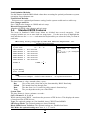
1
USER'S MANUAL
Of
Intel X58 Express Chipset
And
Intel ICH10R Chipset
Based
M/B for Intel Core i7 Processors
NO. G03-BI600 -F
Rev: 2.0
Release date: April, 2009
Trademark:
* Specifications and Information contained in this documentation are furnished for information use only, and are subject to
change at any time without notice, and should not be construed as a commitment by manufacturer.
Environmental Protection Announcement
Do not dispose this electronic device into the trash while discarding. To minimize pollution and
ensure environment protection of mother earth, please recycle.
i
TABLE OF CONTENT
SAFETY ENVIROMENTAL INSTRUCTION ....................................................................iii
USER’S NOTICE.....................................................................................................................iv
MANUAL REVISION INFORMATION ..............................................................................iv
COOLING SOLUTIONS ........................................................................................................iv
CHAPTER 1 INTRODUCTION OF X58 EXPRESS AND ICH10R MOTHERBOARDS
1-1
1-2
1-3
1-4
FEATURES OF MOTHERBOARD .................................................................................... 1
1-1.1 SPECIAL FEATURES OF MOTHERBOARD.................................................... 2
SPECIFICATION.................................................................................................................. 4
PERFORMANCE LIST........................................................................................................ 5
LAYOUT DIAGRAM ........................................................................................................... 6
CHAPTER 2
HARDWARE INSTALLATION
2-1
2-2
2-3
HARDWARE INSTALLATION STEPS............................................................................. 8
CHECKING MOTHERBOARD'S JUMPER SETTING .................................................. 8
INSTALL CPU....................................................................................................................... 9
2-3-1
GLOSSARY............................................................................................................. 9
ABOUT INTEL LGA 1366CPU .......................................................................... 10
2-3-2
2-3-3
LGA 1366 CPU INSTALLATION GUIDE........................................................... 11
2-3-4
INTEL REFERENCE THERMAL SOLUTION ASSEMBLY ........................... 13
2-4 INSTALLING MEMORY .................................................................................................... 14
2-5 EXPANSION CARDS ........................................................................................................... 15
2-5-1
PROCEDURE FOR EXPANSION CARD INSTALLATION ............................ 15
2-5-2
ASSIGNING IRQ FOR EXPANSION CARD...................................................... 15
2-5-3
PCI-EXPRESS SLOT.............................................................................................. 16
2-5-4
INSTALLING THE CROSSFIRE BRIDGE CARD ............................................ 17
2-6 CONNECTORS, HEADERS ................................................................................................ 19
2-6-1
CONNECTORS....................................................................................................... 19
2-6-2
HEADERS ............................................................................................................... 22
2-7 STARTING UP YOUR COMPUTER ................................................................................. 25
CHAPTER 3 INTRODUCING BIOS
3-1 ENTERING SETUP .............................................................................................................. 26
3-2 GETTING HELP ................................................................................................................... 26
3-3 THE MAIN MENU................................................................................................................ 27
3-4 STANDARD BIOS FEATURES........................................................................................... 28
3-5 ADVANCED BIOS FEATURES.......................................................................................... 29
3-6 ADVANCED CHIPSET FEATURES .................................................................................. 30
3-7 INTEGRATED PERIPHERALS ......................................................................................... 30
3-7-1
ONBOARD SATA DEVICE .................................................................................. 30
3-7-2
ONBOARD DEVICE CONTROL......................................................................... 31
3-7-3
SUPER IO CONFIGURATION ............................................................................ 31
3-7-4
USB CONFIGURATION ....................................................................................... 33
3-8 POWER MANAGEMENT FEATURES ............................................................................. 33
3-9 MISCELLANEOUS CONTROL ......................................................................................... 34
3-10 PC HEALTH STATUS.......................................................................................................... 35
3-10-1
SMART FAN CONFIGURATION .................................................................... 35
3-11 POWER USER OVERCLOCK SETTING ......................................................................... 36
3-12 BIOS SECURITY FEATURES ............................................................................................ 36
3-13 LOAD OPTIMIZED DEFAULTS/LOAD FAIL-SAFE DEFAULTS............................... 37
3-14 SAVE CHANGES AND EXIT/ DISCARD AND EXIT ....................................................... 37
CHAPTER 4 DRIVER & FREE PROGRAM INSTALLATION
MAGIC INSTALL SUPPORTS WINDOWS 2000/XP ................................................................ 38
4-1 INF
INSTALL INTELX58 CHIPSET SYSTEM DRIVER.................................... 39
4-2 SOUND INSTALL ALC 888 HD AUDIO CODEC DRIVER....................................... 40
4-3 LAN
INSTALL REALTEK GIGABIT ETHERNET NIC DRIVER....................... 41
4-4 RAID
INSTALL JMICRON RAID DRIVER ............................................................ 41
4-5 NORTON INSTALL NORTON INTERNET SECURITY 2009.................................... 42
4-6 PC-HEALTH INSTALL MYGUARD HARDWARE MONITOR UTILITY .............. 43
4-7 RAID DISK
INSTALL JMICRON RAID DISK.......................................................... 43
4-8 AHCI
INSTALL INTEL AHCI DRIVER ...................................................................... 44
4-9 HOW TO UPDATE BIOS..................................................................................................... 45
4-10 INTEL PLATFORM RAID FUNCTION INTRODUCTION ........................................... 45
4-11 PRO MAGIC PLUS FUNCTION INTRODUCTION........................................................ 47
ii
4-12 G.P.I.FUNCTION LED DISPLAY ...................................................................................... 48
Safety Environmental Instruction
z
Avoid the dusty, humidity and temperature extremes. Do not place the product in
any area where it may become wet.
z
0 to 40 centigrade is the suitable temperature. (The figure comes from the request
of the main chipset)
z
Generally speaking, dramatic changes in temperature may lead to contact
malfunction and crackles due to constant thermal expansion and contraction from
the welding spots’ that connect components and PCB. Computer should go
through an adaptive phase before it boots when it is moved from a cold
environment to a warmer one to avoid condensation phenomenon. These water
drops attached on PCB or the surface of the components can bring about
phenomena as minor as computer instability resulted from corrosion and oxidation
from components and PCB or as major as short circuit that can burn the
components. Suggest starting the computer until the temperature goes up.
z
The increasing temperature of the capacitor may decrease the life of computer.
Using the close case may decrease the life of other device because the higher
temperature in the inner of the case.
z
Attention to the heat sink when you over-clocking. The higher temperature may
decrease the life of the device and burned the capacitor.
iii
USER’S NOTICE
COPYRIGHT OF THIS MANUAL BELONGS TO THE MANUFACTURER. NO PART OF THIS
MANUAL, INCLUDING THE PRODUCTS AND SOFTWARES DESCRIBED IN IT MAY BE
REPRODUCED, TRANSMITTED OR TRANSLATED INTO ANY LANGUAGE IN ANY FORM OR
BY ANY MEANS WITHOUT WRITTEN PERMISSION OF THE MANUFACTURER.
THIS MANUAL CONTAINS ALL INFORMATION REQUIRED FOR THE UTILIZATION OF X58
EXPRESS INTEL EDITION MOTHER-BOARDS TO MEET THE USER’S REQUIREMENTS. BUT
IT WILL CHANGE, CORRECT AT ANY TIME WITHOUT NOTICE. MANUFACTURER PROVIDES
THIS MANUAL “AS IS” WITHOUT WARRANTY OF ANY KIND, AND WILL NOT BE LIABLE FOR
ANY INDIRECT, SPECIAL, INCIDENTIAL OR CONSEQUENTIAL DAMAGES (INCLUDING
DAMANGES FOR LOSS OF PROFIT, LOSS OF BUSINESS, LOSS OF USE OF DATA,
INTERRUPTION OF BUSINESS AND THE LIKE).
PRODUCTS AND CORPORATE NAMES APPEARING IN THIS MANUAL MAY OR MAY NOT BE
REGISTERED TRADEMARKS OR COPYRIGHTS OF THEIR RESPECTIVE COMPANIES, AND
THEY ARE USED ONLY FOR IDENTIFICATION OR EXPLANATION AND TO THE OWNER’S
BENEFIT, WITHOUT INTENT TO INFRINGE.
Manual Revision Information
Reversion
1.0
Revision History
First Edition
Date
Feb., 2009
Item Checklist
5
5
5
5
5
Intel X58 Express and ICH10R chipset based Motherboard
User’s Manual
CD for motherboard utilities
8 in 1 cable package
I/O Back Panel Shield
Intel Core Processor Family
Cooling Solutions
As processor technology pushes to faster speeds and higher performance, thermal management
becomes increasingly crucial while building computer systems. Maintaining the proper thermal
environment is the key to reliable, long-term system operation. The overall goal in providing the
proper thermal environment is keeping the processor below its specified maximum case temperature.
Heat sinks induce improved processor heat dissipation through increased surface area and
concentrated airflow from attached fans. In addition, interface materials allow effective transfers of
heat from the processor to the heat sink. For optimum heat transfer, Intel recommends the use of
thermal grease and mounting clips to attach the heat sink to the processor.
When selecting a thermal solution for your system, please refer to the website below for collection of
heat sinks evaluated and recommended by Intel for use with Intel processors. Note, those heat sinks
are recommended for maintaining the specified Maximum T case requirement. In addition, this
collection is not intended to be a comprehensive listing of all heat sinks that support Intel processors.
iv
Chapter 1
Introduction of X58 Express and ICH10R chipset based Motherboards
1-1
Features of Motherboard
The X58 Express and ICH10R chipset based motherboard series are based on Intel X58
Express chipset and ICH10R chipsets technology which supports the innovative Intel®
Core™ i7-965 processor Extreme Edition, Intel® Core™ i7-940 processors and Intel®
Core™ i7-920 processors with QPI up to 6.4 GT/s.
The X58 Express and ICH10R chipset Based motherboard series deliver the revolutionary
levels of performance enabling vivid, high-definition experiences and multi-tasking
responsiveness from state-of-the-art Intel quad-core technologies, AMD CrossFire technology
through the high bandwidth of dual channel DDR3 1600/1333/1066 MHz system memories
which are expandable to 24 GB capacity and the new generation of PCI Express interface for
the latest graphics cards from both AMD and nVidea. The X58 Express and ICH10R chipset
motherboard series are absolutely the ultimate solution for game enthusiasts and applications,
and it also meets the demanding usage of computing of gaming, multimedia entertainment
and business applications.
The Intel X58 Express and ICH10R chipset motherboard series are embedded with ICH10R
chipset of providing six serial ATA2 interfaces of 3.0 Gb / s data transfer rate for six serial
ATA devices which supports RAID 0, 1,5,10 functions. More over, the motherboard provides
also extra 1 Ultra ATA interface for two IDE devices of 133 MB / s data transfer rate and two
external serial ATA interface of 3.0 Gb / s data transfer rate for two external serial ATA hard
disk devices.
The X58 Express and ICH10R chipset Based motherboard provides Gigabit LAN function by
using two Realtek RTL8111C PCI Gigabit LAN chips which support 10M / 100M / 1Gbps
data transfer rate. Embedded 8-channel ALC888 HD CODEC is fully compatible with Sound
Blaster Pro® standards that offer you with the home cinema quality and absolutely software
compatibility.
The X58 Express chipset based motherboard series offer four PCI-Express2.0 x16 graphics
slots with PE1 and PE4 being PCI Express 2.0 x16@16 lane slots while PE3 and PE5 being
PCI Express 2.0 x16@ 8 lane slots. These four graphics slots are fully compatible with the
latest AMD CrossFireX Technology to guarantee the fully operational Multi-GPUs graphics
function and avoid the possible installation error. One PCI Express x4 I/O slot and one 32-bit
PCI slots guarantee the rich connectivity for the I/O of peripherals.
Embedded USB controllers as well as capability of expanding to 12 of USB2.0 functional
ports delivering 480Mb/s bandwidth of rich connectivity, these motherboards meet the future
USB demands which are also equipped with hardware monitor function on system to monitor
and protect your system and maintain your non-stop business computing.
Some special features---CPU Thermal Throttling/ CPU Smart Fan/ CPU Vcore X-shift/
Debug Port/OC-CON/G.P.I. Function/DIY Clear/Power on Button/Reset Button in this
motherboard are designed for power user to use the over-clocking function in more flexible
1
ways. But please be caution that the over-clocking may cause the failure in system reliability.
This motherboard provides the guaranteed performance and meets the demands of the next
generation computing. But if you insist to gain more system performance with variety
possibilities of the components you choose, please be careful and make sure to read the
detailed descriptions of these value added product features, please get them in the coming
section.
1-1.1 Special Features of motherboard
CPU Thermal Throttling Technology--- (The CPU Overheat Protection Technology)
To prevent the increasing heat from damage of CPU or accidental shutdown while at high
workload, the CPU Thermal Throttling Technology will force CPU to enter partially idle
mode from 87.5% to 12.5% according to preset CPU operating temperature in BIOS (from 40
℃ to 90℃). When the system senses the CPU operating temperature reaching the preset
value, the CPU operating bandwidth will be decreased to the preset idle percentage to cool
down the processor. When at throttling mode the beeper sound can be optionally selected to
indicate it is in working.
CPU Smart Fan--- The Noise Management System
It’s never been a good idea to gain the performance of your system by sacrificing its acoustics.
CPU Smart Fan Noise Management System is the answer to control the noise level needed for
now-a-day’s high performance computing system. The system will automatically increase the
fan speed when CPU operating loading is high, after the CPU is in normal operating
condition, the system will low down the fan speed for the silent operating environment. The
system can provide the much longer life cycle for both CPU and the system fans for game use
and business requirements.
CPU Vcore X-Shift--- Shift to Higher Performance
The CPU voltage can be adjusted up by 31 stages for the precisely over-clocking of extra
demanding computing performance.
Debug Port--- The Professional Hardware Diagnosis System
Being bugged of abnormal system failure through the tossed and turned nights no more, the
embedded Hardware Debug Port offers you the real-time visual system healthy for the
demanding usage of computing. No more bugging by unknown system failure and no more
time wasted in the first moment of 24-hour nonstop ping business computing, the embedded
Debug Port will turn you into a well training hardware professional with the seeing system
situation. (The Post Code please refer Appendix)
OC-CON ---High-polymer Solid Electrolysis Aluminum Capacitors (Optional for HI04
series only)
The working temperature is from 55 degrees Centigrade below zero to 125 degrees
Centigrade, OC-CON capacitors possess superior physical characteristics that can be while
reducing the working temperature between 20 degrees Centigrade each time, intact extension
10 times of effective product operation lives, at not rising degrees Centigrade of working
temperatures each time a relative one, life of product decline 10% only too.
2
G.P.I. Function—(Green power indicator function)
The full name of G.P.I technology is Green Power Indicator technology, obviously
technology utilized to low power consumption. G.P.I is a technology with remarkable power
saving function.
DIY Clear
The CMOS Button is to facilitate the clear COMS process for power user overclocking
function. The user can easily clear or restore COMS settings by pressing down the button,
without taking trouble to remove the case and locate the jumper for clear CMOS.
Power on Button
You can easily start the computer by pressing down this button for a few seconds, without
troubling yourself to locate the front panel jumpers to find the Power on jumper.
Reset Button
You can easily restart the computer by pressing down this button for a few seconds, without
troubling yourself to locate the front panel jumpers to find the reset jumper.
3
1-2
Specification
Spec
Design
Chipset
CPU Socket
LGA 1366
Memory Sockets
Expansion Slots
Description
∗
∗
∗
∗
∗
∗
∗
∗
ATX form factor 6 layers PCB size: 30.5x24.5cm
Intel X58 Express Chipset
Intel ICH10R chipset
Supports the Intel® Core™ i7-965 processor Extreme Edition,
Intel® Core™ i7-940 processors and Intel® Core™ i7-920
processors.
Support QPI up to 6.4 GT/s
DDR3 Module sockets x 6,
Support 6 pcs DDR3 1600 /DDR3 1333MHz/ DDR3 1066
memory modules expandable to 24GB.
Support Dual- channel / Three-channel function
PCI-Express2.0 x16 slot 4pcs
PCI-Express2.0 x4 slot 1pcs
32-bit PCI slot x 1pcs
The Intel ICH10R supports six internal Serial ATA ports for six
SATA devices with RAID0, RAID1, RAID5 and PAID10
function providing 3.0 Gb/sec data transfer rate.
JMB363 supports PCI Bus Mastering, ATA PIO/DMA and the
ULTRA DMA 66 / 100/133 functions that deliver the data
transfer rate up to 133 MB/s for two IDE Devices and two
external Serial ATA ports providing 3.0 Gb /sec data transfer
rate for two serial ATA devices
Integrated Realtek RTL8111C PCI-E Gigabit LAN function.
Supports Fast Ethernet LAN function provide 10Mb/100Mb/
1Gb /s data transfer rate.
Realtek ALC888 Azalia 8-channel HD Audio Codec integrated
Support 8-channel 3D surround & Positioning Audio
Audio driver and utility included
AMI 8MB SPI Flash ROM
∗
∗
∗
∗
∗
∗
∗
∗
∗
∗
PS/2 keyboard and PS/2 mouse connectors
ESATA connectors x2, SATA connectors x6
Coaxial S/PDIF Out connector x1
USB2.0 port x 8 and headers x2
RJ-45 LAN connector x2
Audio connector x1 (8-CH Audio)
Floppy disk drive connector x1,Hard disk drive connector x1
Serial Port headerx1
HDMI-SPDIF header x1
IR header x 1
∗
∗
∗
∗
∗
∗
∗
∗
Integrate IDE and ∗
Serial ATA2 RAID
Gigabit LAN
8CH-Audio
BIOS
Multi I/O
∗
∗
4
1-3
Performance List
The following performance data list is the testing result of some popular benchmark testing
programs. These data are just referred by users, and there is no responsibility for different
testing data values gotten by users (the different Hardware & Software configuration will
result in different benchmark testing results.)
Test Configuration:
CPU:
Core i7 920
DRAM:
Apacer DDR3 1333 2GB x2
VGA Card:
ATI 3850
Hard Disk Driver:
Seagat SATA 160GB
BIOS:
3D Mark 2001SE
T003
34578
3D Mark 2003
13117
3D Mark 2005
7544
N/G
AQUAMRK3
PCMark2005
7324/8095/6354
System / CPU / Memory
5499/6247
Graph / HDD
Content Creation Winstone 2004
49.3
Business Winstone 2004
32.4
Winbench 99 V2.0:
225001.3
SYSMark 2007: SISMark Rating(Internet Content Creation / Office Productivity )
Business /Hi-end Disk Winmark99
151
E-learning
Video Creation
164
productively
138
3D
211
System Mark Preview Rating
164
296
SISOFT Sandra 2009 : 1.CPU Arithmetic Benchmark 2.CPU Multi-Media Benchmark 3.Memory bandwidth
Benchmark
1.DHRYSTON ALU
GIPS
70.66GIPS
DATA Analysis
WHETSTONE ISSE2
GFLOPS
2. Int/Float Buffered iSSE2
MB/S
62.53GFlops
13.59GB/S,13.63GB/S
3. Integer/Floating-Point SSE2 IT/S
124.61,100.38 Mpixel/s
UT2003 Benchmark (flyby/botmatch)
542.181702/178.297337
Quake3 DEMO1 / DEMO2
FPS
Super Pi (1M)
Second
CPUZ
N/A
15.34”
2.66GHZ
System / CPU Clock
5
1-4
Layout Diagram
Line IN
(Blue)
RJ-45 Ports
ESATA Connectors
CEN/BASS
(Black)
Line OUT (Green)
Surrback
(Orange)
PS/2Mouse
(Green)
PS/2 Keyboard
CMOS2
(Purple)
Surround
SPDIF-OUT1
(Gray)
MIC-IN
(Pink)
USB connectors
KB/MS Power On Jumper (JP1)
PS2 KB/Mouse Port
ATX 12V Power Conn.
Coaxial S/PDIF out.
CMOS2
DDR3 1600 DIMMs
E-SATA Ports
over USB Ports
LGA 1366 CPU Socket
RJ45 Ports
Over USB Ports
USB Power On Jumper (JP3)
ATX Power Connector
CPU FAN
Audio Connector
RTL8111C
Gigabit LAN Chips
Intel X58 Express
Chipset
PCI-E 2.0 x16 @ 16 lane
(PE1, PE4)
8Mbit SPI Flash ROM BIOS
SYS FAN2
Intel
ICH10R
Chipset
PCI-E2.0 x4 slot
Serial-ATA2 Connectors
(D-SATA1, D-SATA2,
D-SATA3)
Clear CMOS (JBAT)
PCI-E 2.0 x16 @ 8 lane
(PE3, PE5)
SYS FAN1
IR Header
Reset Button
Power on Button
COMS1 Button
32-bit PCI Slot
8-CH Azalia Audio Codec
Power LED /
Speaker Headers
HDMI-SPDIF
Front Panel Audio Header
Serial Port Header
ATA 133 IDE
Connector
Floppy Connector
CD Audio In
USB headers Front Panel
Header
USB Power On Jumper (JP4)
6
Jumpers
Jumper
JBAT
JP1
JP3/JP4
Name
CMOS RAM Clear
Keyboard Power On Enabled/Disabled
USB Power On Enabled/Disabled
Connectors
Connector
ATXPWR1
ATX12V1
KB1
USB from CN1,CN2 and
UL1, UL2
RJ45 LAN from UL1,UL2
AUDIO1
FLOPPY1
IDE1
DSATA1,DSATA2,
DSATA3
E-SATA from CN1,CN2
SPDIF_ Out1
Headers
Header
FP_AUDIO1
USB1,USB2
SPEAK
PWR LED
JW_FP(PWR LED/Reset/
HD LED/PWR BTN)
CPUFAN1
SYSFAN1, SYSFAN2
CDIN1
IR1
COM1
HDMI-SPDIF1
Expansion Sockets
Socket/Slot
LGA 1366 Socket
DIMM_A2/DIMM_A1/
DIMM_B2/DIMM_B1/
DIMM_C2/DIMM_C1
PCI1
PE2
PE1,PE3,PE4,PE5
Description
3-pin Block
3-pin Block
3-pin Block
Page
P.8
P.9
P.9
Name
ATX Power Connector
ATX 12V Power Connector
PS/2 Mouse & PS/2 Keyboard Connector
Description
24-pin Block
8-pin Block
6-pin Female
Page
P.18
P.18
P.19
USB 2.0 Port Connectors
4-pin Connector
P.19
RJ-45 LAN Port Over USB Connectors.
8-CH Audio Connector
P.19
P.19
Floppy Driver Connector
IDE Connector
Serial ATA2 Connector
RJ-45 Connector
6 phone jack
Connector
34-pin Block
40-pin Block
7-pin Connector
P.19
P.20
P.20
External Serial ATA2 Connectors
Coaxial S/PDIF Out Connector
7-pin Connector
1phone connector
P.21
P.21
Name
SPEAKER, MIC header
USB Port Headers
PC Speaker header
Power LED header
Front Panel Header
(including Power LED/ IDE activity
LED/Reset switch / Power On Button lead)
CPUFAN Header
System FAN Headers
CD Audio-In Header
IR Header
Serial Port COM1 Header
SPDIF-Out header
Name
CPU Socket
DDR3 Module Sockets
Description
9-pin Block
9-pin Block
4-pin Block
3-pin Block
9-pin Block
Page
P.21
P.21
P.21
P.21
P.21
4-pin Block
3-pin Block
4-pin Block
5-pin Block
9-pin Block
2-pin Block
P.22
P.22
P.22
P.23
P.23
P.23
Description
LGA 1366 CPU Socket
240-pin DDR3 Module Sockets
PCI Slot
32-bit PCI Local Bus Expansion slots
PCI-Express2.0 x4 Slot PCI-Express2.0 x 4Expansion Slots
PCI-Express 2.0x 16 PCI-Express2.0 x16 Expansion Slots
Slots
7
Page
P.10
P.14
P.16
P.16
P.16
Chapter 2
Hardware Installation
WARNING!
2-1
Turn off your power when adding or removing expansion cards or other
system components. Failure to do so may cause severe damage to both
your motherboard and expansion cards.
Hardware installation Steps
Before using your computer, you had better complete the following steps:
1. Check motherboard jumper setting
2. Install CPU and Fan
3. Install System Memory (DIMM)
4. Install Expansion cards
5. Connect IDE Front Panel /Back Panel cable
6. Connect ATX Power cable
7. Power-On and Load Standard Default
8. Reboot
9. Install Operating System
10. Install Driver and Utility
2-2
(1)
Checking Motherboard’s Jumper Setting
CMOS RAM Clear (3-pin) : JBAT1
A battery must be used to retain the motherboard configuration in CMOS RAM short 1-2
pins of JBAT to store the CMOS data.
To clear the CMOS, follow the procedure below:
1. Turn off the system and unplug the AC power
2. Remove ATX power cable from ATX power connector
3. Locate JBAT and short pins 2-3 for a few seconds
4. Return JBAT to its normal setting by shorting pins 1-2
5. Connect ATX power cable back to ATX power connector
Note: When should clear CMOS
1. Troubleshooting
2. Forget password
3. After over clocking system boot fail
JBAT
JBAT
1-2 Closed
Normal
2-3 Closed
CMOS RAM Clear Setting
8
Clear CMOS
(2)
Keyboard function Enabled/Disabled: JP1
JP1
JP1
2-3 Closed KB Power ON Enabled
1-2 Closed KB Power ON Disable (Default)
Keyboard/Mouse Power On Setting
(3)
USB Power On function Enabled/Disabled: JP3/JP4
JP3 / JP4
1-2 closed
(Default)
JP3 / JP4
USB Power On Disable
2-3 closed
USB Power On Enabled
USB Power-On Setting
2-3 Installing CPU
2-3-1 Glossary
Chipset (or core logic) - two or more integrated circuits which control the interfaces between
the system processor, RAM, I/O devises, and adapter cards.
Processor slot/socket - the slot or socket used to mount the system processor on the
motherboard.
Slot (PCI-E, PCI, RAM) - the slots used to mount adapter cards and system RAM.
PCI - Peripheral Component Interconnect - a high speed interface for video cards, sound
cards, network interface cards, and modems; runs at 33MHz.
PCI Express2.0- Peripheral Component Interconnect Express2.0, developed in 2003, the
speed of each line doubled from the previous PCI-E of 2.5Gbps to 5 Gbps.
Serial Port - a low speed interface typically used for mouse and external modems.
Parallel Port - a low speed interface typically used for printers.
PS/2 - a low speed interface used for mouse and keyboards.
USB - Universal Serial Bus - a medium speed interface typically used for mouse, keyboards,
scanners, and some digital cameras.
Sound (interface) - the interface between the sound card or integrated sound connectors and
speakers, MIC, game controllers, and MIDI sound devices.
LAN (interface) - Local Area Network - the interface to your local area network.
BIOS (Basic Input/Output System) - the program logic used to boot up a computer and
establish the relationship between the various components.
Driver - software, which defines the characteristics of a device for use by another device or
other software.
9
Processor - the "central processing unit" (CPU); the principal integrated circuit used for
doing the "computing" in "personal computer"
Front Side Bus Frequency - the working frequency of the motherboard, which is generated
by the clock generator for CPU, DRAM and PCI BUS.
CPU L2 Cache - the flash memory inside the CPU, normal it depend on CPU type.
2-3-2 About Intel LGA 1366 CPU
This motherboard provides a 1366-pin DIP, LGA 1366 Land Grid Array socket, referred to as
the LGA 1366 socket.
The CPU that comes with the motherboard should have a cooling FAN attached to prevent
overheating. If this is not the case, then purchase a correct cooling FAN before you turn on
your system.
NOTED!
Be sure that there is sufficient air circulation across the processor’s heat
sink and CPU cooling FAN is working correctly, otherwise it may cause
the processor and motherboard overheat and damage, you may install an
auxiliary cooling FAN, if necessary.
To install a CPU, first turn off your system and remove its cover. Locate the LGA 1366
socket and open it by first pulling the level sideways away from the socket then upward to a
135-degree angle. Insert the CPU with the correct orientation as shown below. The
notched corner should point toward the end of the level. Because the CPU has a corner pin
for two of the four corners, the CPU will only fit in the orientation as shown.
When you install the CPU into the LGA 1366 socket, there’s no force required CPU insertion;
then press the level to locate position slightly without any extra force.
Pin-1
Indicator
Alignment key
10
2-3-3
1.
LGA 1366 CPU Installation Guide
Please make sure that CPU socket is facing towards
2.
you and the level is on you left hand side.
3. Pick up the lode plate upwards about 100 degree to
4.
Press down the level and move iit to the left side to
make sure it is freed from the hook and then open it
upwards about 135 degree.
Remove the plastic protective cap from the socket.
( Put it to the original place if CPU is not installed . Do
make sure it is moved upwards.
not touch the metal contact point of the CPU socket).
11
Alignment
Key
Alignment
Key
Pin-1
Indicator
5.
Make sire that golden finger is on the left-down side as shown and match the two alignment keys
on the CPU with two points of the socket. CPU can only be correctly installed with this direction.
Incorrect installation might cause damage to CPU .
6.Put down the load plate.
7. Press down the load level and move it rightwards make
sure it is locked under the notch.
12
2-3-4 Intel Reference Thermal Solution Assembly
Align
the
fastener with
the hole
1.
Put the heat sink vertically above the CP-installed
2. Revolve
the four fasteners in the counter-clockwise
socket and make sure to align the four fasteners with
four holes around the socket.
direction.
Motherboard
3. Press down two fasteners down in the oblique crossing 4.
direction as shown above.
Turn over the motherboard carefully to make sure the
fastener insert in the right direction.
Notice:
Please apply thermal interface material to the CPU HIS surface;
The heat sink and installation steps are for reference use only; Installation steps might
differ depending on different heat sink models;
Please use Intel original heat sink for better heat dissipation or other heat sinks that has
pass Intel certification.
13
2-4
Installing Memory
This motherboard provides six 240-pin DDR3 DUAL INLINE MEMORY MODULES
(DIMM) socket for DDR3 memory modules capacity expansion to maximum memory
volume of 24 GB.
Valid Memory Configurations for DDR3
Number of slot(s)
Recommended Installing DIMM
Working Mode
DIMM_A1
Single Channel
One
DIMM_A1
&
DIMM_B1
Dual Channel
Two
DIMM_A1 & DIMM_B1& DIMM_C1
3-Channel
Three
3-Channel
DIMM_A1 & DIMM_B1& DIMM_C1
Four
Five
Six
& DIMM_A2
DIMM_A1 & DIMM_B1& DIMM_C1
& DIMM_A2 & DIMM_B2
ALL DIMMs
3-Channel
3-Channel
Notice!
If there is only one memory module, you should install it only in one of DIMM_A1,
DIMM_B1 and DIMM_C1 slot; otherwise system won’t start.
With two memory modules, you can only install them in two slots of the
DIMM_A1, DIMM_B1 and DIMM_C1 to enjoy dual channel function.
With three or more memory modules, you should install three of them in DIMM_A1,
DIMM_B1 and DIMM_C1 in the first place to enjoy 3-channel function.
Installing memory modules on your motherboard is an easy process in most cases. You
might as well refer to the following pictures when installing your memory modules. Please
make sure the power is cut off in the first place.
installation Tips:
Open the two plastic clips of memory slots then push down the module vertically into
the slot. See to it that the hole of the module fit into the notch of the slot;
The two plastic clips will automatically close if the memory module is fitted in a
proper way.
14
2-5
Expansion Cards
2-5-1 Procedure For Expansion Card Installation
1. Read the documentation for your expansion card and make any necessary hardware or
software setting for your expansion card such as jumpers.
2. Remove your computer’s cover and the bracket plate on the slot you intend to use.
3. Align the card’s connectors and press firmly.
4. Secure the card on the slot with the screen you remove above.
5. Replace the computer system’s cover.
6. Set up the BIOS if necessary.
7. Install the necessary software driver for your expansion card.
2-5-2 Assigning IRQs for Expansion Card
Some expansion cards need to set up the IRQ to operate. An IRQ must be assigned
exclusively to single interface use only. There are 16 IRQs available but most of them are
already being used.
Standard Interrupt Assignments
IRQ
0
1
2
3*
4*
5*
6*
7*
8
9*
10 *
11 *
12 *
13
14 *
15 *
Priority
N/A
N/A
N/A
8
9
6
11
7
N/A
10
3
2
4
N/A
5
1
Standard function
System Timer
Keyboard Controller
Programmable Interrupt
Communications Port (COM2)
Communications Port (COM1)
Sound Card (sometimes LPT2)
Floppy Disk Controller
Printer Port (LPT1)
System CMOS/Real Time Clock
ACPI Mode when enabled
IRQ Holder for PCI Steering
IRQ Holder for PCI Steering
PS/2 Compatible Mouse Port
Numeric Data Processor
Primary IDE Channel
Secondary IDE Channel
* These IRQs are usually available for ISA or PCI devices.
15
2-5-3 PCI Express Slot
The X58 Express chipset based motherboard series offer four PCI-Express2.0 x16 graphics
slots with PE1 and PE4 being PCI Express 2.0 x16@16 lane slots while PE3 and PE5 being
PCI Express 2.0 x16@ 8 lane slots. These four graphics slots are fully compatible with the
latest AMD CrossFireX Technology to guarantee the fully operational Multi-GPUs graphics
function and avoid the possible installation error. One PCI Express x4 I/O slot and one 32-bit
PCI slots guarantee the rich connectivity for the I/O of peripherals.
PCI-E2.0 x4Slot
PCI-E2.0 x16@16 Lane Slot
PCI-E2.0 x16@8 Lane Slots
PCI Slots
16
2-5-4 Installing the CrossFire Bridge Card
The following illustrations show you how to install the CrossFire Bridge Card.
Bridge for CrossFire Tech. Supported VGA Cards
In order to activate the CrossFire technology, you have to install the optional Bridge for your
CrossFire Tech. Supported VGA Cards before you activating the advance multi-GPUs
functions.
For CrissFire Bridge installation
1.
Install your CrossFire Tech Supported VGA
Cards in the PCI-E x16 slots.
2.
Prepare with the CF Bridges with your
crossFire Tech Supported VGA Cards.
3.
Be careful with the position for the pin you
would like to set up.
4.
Keep straight to force the CF Bridges plug
into both sides of CrossFire Tech
Supported VGA Cards.
17
Notice!
The motherboard and graphics card in the illustration is for reference use only;
We suggest that you install graphics cards in PE1 and PE4 slot for better CrossFire
performance;
We suggest that you install graphics cards in PE1,PE3 and PE4 slots for better
performance when installing 3 graphics card.
18
2-6
Connectors, Headers
2-6-1 Connectors
(1)
Power Connector (24-pin block): ATXPWR1
ATX Power Supply connector: This is a new defined 24-pins connector that usually
comes with ATX case. The ATX Power Supply allows using soft power on momentary
switch that connect from the front panel switch to 2-pins Power On jumper pole on the
motherboard. When the power switch on the back of the ATX power supply turned on,
the full power will not come into the system board until the front panel switch is
momentarily pressed. Press this switch again will turn off the power to the system
board.
** We recommend that you use an ATX 12V Specification 2.0-compliant power supply
unit (PSU) with a minimum of 350W power rating. This type has 24-pin and 4-pin
power plugs.
** If you intend to use a PSU with 20-pin and 4-pin power plugs, make sure that the 20-pin
power plug can provide at least 15A on +12V and the power supply unit has a minimum
power rating of 350W. The system may become unstable or may not boot up if the
ROW1 ROW2
power is inadequate.
PIN
ROW1 ROW2
Pin 1
Pin 1
20-Pin
24-Pin
ROW1
ROW2
1
3.3V
3.3V
2
3.3V
-12V
3
GND
GND
4
5V
Soft Power On
5
GND
GND
6
5V
GND
7
GND
GND
8
Power OK
-5V
9
+5V (for Soft Logic)
+5V
10
+12V
+5V
11
+12V
+5V
12
+3V
GND
(2) ATX 12V Power Connector (8-pin block) : ATX12V1
This is a new defined 8-pin connector that usually comes with ATX Power Supply. The
ATX Power Supply which fully supports LGA 1366 processor must including this
connector for support extra 12V voltage to maintain system power consumption.
Without this connector might cause system unstable because the power supply can not
provide sufficient current for system.
19
Pin 1
(3) PS/2 Mouse & PS/2 Keyboard Connector: KB1
The connectors are for PS/2 keyboard and PS/2 Mouse input devices.
(4) USB Port connector: USB port from CN1, CN2 and UL1, UL2
The connectors are 4-pin connectors that connect USB devices with the 400Mbit / sec
data transfer rate to the system board.
(5) LAN Port connector: RJ-45 LAN port from UL1, UL2
This connector is standard RJ45 over USB connectors for Network connection. The
connector supports 10MB/100MB/1G B/s data transfer rate
(6)
Audio Line-In, Lin-Out, MIC, Surrback, Surround, CEN/BASS Connector: AUDIO1
These Connectors are 6 Phone-Jack for LINE-OUT, LINE-IN, MIC, Surrback, Surround,
CEN/LEF audio connections.
Audio input to sound chip
Line-in : (BLUE)
Audio output to speaker
Line-out : (GREEN)
Microphone Connector
MIC : (PINK)
Audio output to speaker-Rear speaker out
Surrback : (ORANGE)
Audio output to speaker-Center/Subwoofer speaker out
CEN/BASS : (BLACK)
ESATA Connectors
RJ-45 Ports
Line IN
(Blue)
CEN/BASS
(Black)
Line OUT (Green)
Surrback
(Orange)
PS/2Mouse
(Green)
PS/2 Keyboard
CMOS2
(Purple)
Surround (Gray)
SPDIF-OUT1
USB connectors
MIC-IN
(Pink)
(7) Floppy drive Connector (34-pin block): FLOPPY1
This connector supports the provided floppy drive ribbon cable. After connecting the
single plug end to motherboard, connect the two plugs at other end to the floppy drives.
20
Pin 1
FLOPPY
(Black)
Floppy Drive Connector
(8) IDE Connector (40-pin block): IDE1
This connector supports the provided IDE hard disk ribbon cable. After connecting the
single plug end to motherboard, connect the two plugs at other end to your hard disk(s).
If you install two hard disks, you must configure the second drive to Slave mode.
IDE1
Pin 1
Primary IDE Connector(Black)
• Two hard disks can be connected to each connector. The first HDD is referred to as the
“Master” and the second HDD is referred to as the “Slave”.
• For performance issues, we strongly suggest you don’t install a CD-ROM or DVD-ROM
drive on the same IDE channel as a hard disk..Otherwise, the system performance on this
channel may drop.
(9) Serial-ATA2 Port connectors: DSATA1 / DSATA2 / DSATA3
These connectors support the provided Serial ATA and Serial ATA2 IDE hard disk cable
to connect the motherboard and serial ATA2 hard disk drives.
DSATA3
DSATA2
DSATA1
Serial-ATA2 Compatible Connectors
21
(10) ESATA Port: ESATA ports from CN1, CN2
These two connectors support the External Serial ATA2 (eSATA) to enable the full SATA
interface speed outside the chassis.
(11) SPDIF Out connectors: SPDIF_Out1
The SPDIF output is capable of providing digital audio to external speakers or compressed
AC3 data to an external Dolby digital decoder. Use this feature only when your stereo system
has digital input function.
2-6-2 Headers
AU D IO
KEY
LINE2-JD
Audio-JD
MIC2-JD
Audio-GND
(1) Line-Out/MIC Header for Front Panel (9-pin): FP_AUDIO1
These headers connect to Front Panel Line-out, MIC connector with cable.
2
10
P in 1
Sense-FB
Lineout2-L
Lineout2-R
MIC2-R
MIC2-L
9
L ine-O ut, M IC H eaders
VCC
- DATA
VCC
-DATA
+DATA
GND
OC
(2) USB Port Headers (9-pin): USB1/USB2
These headers are used for connecting the additional USB port plugs. By attaching an
option USB cable, your can be provided with two additional USB plugs affixed to the
back panel.
+DATA
GND
Pin 1
USB Port Header
(3) Speaker connector: SPEAK
This 4-pin connector connects to the case-mounted speaker. See the figure below.
(4) Power LED: PWR LED
The Power LED is light on while the system power is on. Connect the Power LED from
the system case to this pin.
(5) IDE Activity LED: HD LED
This connector connects to the hard disk activity indicator light on the case.
(6) Reset switch lead: RESET
This 2-pin connector connects to the case-mounted reset switch for rebooting your
computer without having to turn off your power switch. This is a preferred method of
22
JW FP
PWRBTN
GND
PWRBTN
PWRLED
Pin 1
PWRLED
VCC5
PWR LED
rebooting in order to prolong the lift of the system’s power supply. See the figure
below.
(7) Power switch: PWR BTN
This 2-pin connector connects to the case-mounted power switch to power ON/OFF the
system.
SPEAK
VCC5
HDDLE
GND
RSTSW
NC
HDLED
RESET
GND
VCC5
Pin 1
SPKR
NC
Pin 1
System Case Connections
(8) FAN Headers: SYSFAN1, SYSFAN2 (3-pin), CPUFAN1 (4-pin)
These connectors support cooling fans of 350mA (4.2 Watts) or less, depending on the
fan manufacturer, the wire and plug may be different. The red wire should be positive,
while the black should be ground. Please connect the fan’s plug to the board taking into
consideration the polarity of connector.
CPUFAN
1
4
1
SYSFAN2
3
SYSFAN1
1
3
(9) CD Audio-In Headers (4-pin) : CDIN1
CDIN are the connectors for CD-Audio Input signal. Please connect it to CD-ROM
CD-Audio output connector.
CDIN
4
1
CD Audio-In Headers
23
GND
IR
+5VX
(10) IR infrared module Headers (5-pin): IR1
This connector supports the optional wireless transmitting and receiving infrared
module. You must configure the setting through the BIOS setup to use the IR function.
2
6
5
IRRX
GND
IRTX
Pin 1
IR infrared module Headers
(11)
Serial COM Port header: COM1
COM1 is a 9-pin RS232 connector.
Pin1
Serial COM Port 9-pin Block
(12) SPDIF Out header: HDMI_SPDIF
The SPDIF output is capable of providing digital audio to external speakers or compressed
AC3 data to an external Dolby digital decoder. Use this feature only when your stereo system
has digital input function.
SPDIF
HDMI_SPDIF_OUT
GND
1
24
2
2-7
Starting Up Your Computer
1. After all connection is made, close your computer case cover.
2. Be sure all the switch are off, and check that the power supply input voltage is set to
proper position, usually in-put voltage is 220V∼240V or 110V∼120V depending on your
country’s voltage used.
3. Connect the power supply cord into the power supply located on the back of your system
case according to your system user’s manual.
4. Turn on your peripheral as following order:
a. Your monitor.
b. Other external peripheral (Printer, Scanner, External Modem etc…)
c. Your system power. For ATX power supplies, you need to turn on the power
supply and press the ATX power switch on the front side of the case.
5. The power LED on the front panel of the system case will light. The LED on the
monitor may light up or switch between orange and green after the system is on. If it
complies with green standards or if it is has a power standby feature. The system will
then run power-on test. While the test are running, the BIOS will alarm beeps or
additional message will appear on the screen.
If you do not see any thing within 30 seconds from the time you turn on the power. The
system may have failed on power-on test. Recheck your jumper settings and connections
or call your retailer for assistance.
Beep
Meaning
One short beep when displaying logo
No error during POST
Long beeps in an endless loop
No DRAM install or detected
One long beep followed by two short
beeps
No VGA card found or error found in monitor
High frequency beeps when system is
working
CPU overheated
System running at a lower frequency
6. During power-on, press <Delete> key to enter BIOS setup.
BIOS SETUP.
Follow the instructions in
7. Power off your computer: You must first exit or shut down your operating system
before switch off the power switch. For ATX power supply, you can press ATX power
switching after exiting or shutting down your operating system. If you use Windows 9X,
click “Start” button, click “Shut down” and then click “Shut down the computer?”
The power supply should turn off after windows shut down.
25
Chapter 3
Introducing BIOS
The BIOS is a program located on a Flash Memory on the motherboard. This program is a
bridge between motherboard and operating system. When you start the computer, the BIOS
program will gain control. The BIOS first operates an auto-diagnostic test called POST
(power on self test) for all the necessary hardware, it detects the entire hardware device and
configures the parameters of the hardware synchronization. Only when these tasks are
completed done it gives up control of the computer to operating system (OS). Since the
BIOS is the only channel for hardware and software to communicate, it is the key factor for
system stability, and in ensuring that your system performance as its best.
In the BIOS Setup main menu of Figure 3-1, you can see several options. We will explain
these options step by step in the following pages of this chapter, but let us first see a short
description of the function keys you may use here:
•
Press <Esc> to quit the BIOS Setup.
•
Press ↑ ↓ ← → (up, down, left, right) to choose, in the main menu, the option you want to
confirm or to modify.
•
Press <F10> when you have completed the setup of BIOS parameters to save these
parameters and to exit the BIOS Setup menu.
•
Press <+>/<–> keys when you want to modify the BIOS parameters for the active option.
3-1
Entering Setup
Power on the computer and by pressing <Del> immediately allows you to enter Setup.
If the message disappears before your respond and you still wish to enter Setup, restart the
system to try again by turning it OFF then ON or pressing the “RESET” button on the system
case. You may also restart by simultaneously pressing <Ctrl>, <Alt> and <Delete> keys. If
you do not press the keys at the correct time and the system does not boot, an error message
will be displayed and you will again be asked to
Press
<Del> to enter Setup
3-2
Getting Help
Main Menu
The on-line description of the highlighted setup function is displayed at the bottom of the
screen.
Status Page Setup Menu/Option Page Setup Menu
Press F1 to pop up a small help window that describes the appropriate keys to use and the
possible selections for the highlighted item. To exit the Help Window, press <Esc>.
26
3-3
The Main Menu
Once you enter AMI BIOS Setup Utility, the Main Menu (Figure 3-1) will appear on the
screen. The Main Menu allows you to select from 12 setup functions and 2 exit choices.
Use arrow keys to select among the items and press <Enter> to accept or enter the sub-menu.
CMOS Setup Utility-Copyright(C)1985-2005 American Megatrends. Inc.
Standard BIOS Features
Power User Overclock Settings
Advanced BIOS Features
BIOS Security Features
Advanced Chipset Features
Load Optimized Defaults
Integrated Peripherals
Load Fail-Safe Defaults
Power Management Features
Save Changes and Exit
Miscellaneous Control
Discard Changes and Exit
PC Health Status
↑↓→←: Move
Enter: Select +/-/: Value F10: Save ESC:Exit F1:General Help
F5:Discard Changes
F6:Fail-Safe Defaults
F7:Optimized Defaults
V 0.265(C) Copyright 1985-2008, American Megatrends, Inc.
Figure 3-1
Standard BIOS Features
Use this Menu for basic system configurations.
Advanced BIOS Features
Use this menu to set the Advanced Features available on your system.
Advanced Chipset Features
Use this menu to change the values in the chipset registers and optimize your system’s
performance.
Integrated Peripherals
Use this menu to specify your settings for integrated peripherals.
Power Management Features
Use this menu to specify your settings for power management features
Miscellaneous Control
Use this menu to specify your settings for Miscellaneous Control.
PC Health Status
Use this item to configure hardware health status.
Power User Overclock Settings
Use this menu to specify your settings (frequency, Voltage) for overclocking demand.
BIOS Security Features
This entry for setting Supervisor password and User password
27
Load Optimized Defaults
Use this menu to load the BIOS default values these are setting for optimal performances system
operations for performance use.
Load Failsafe Defaults
This menu uses a minimal performance setting, but the system would run in a stable way.
Save Changes and Exit
Save CMOS value changes to CMOS and exit setup.
Discard Changes and Exit
Abandon all CMOS value changes and exit setup.
3-4
Standard BIOS Features
The items in Standard CMOS Setup Menu are divided into several categories. Each
category includes no, one or more than one setup items. Use the arrow keys to highlight the
item and then use the <+> or <-> and numerical keyboard keys to select the value you want in
each item.
CMOS Setup Utility-Copyright(C)1985-2005 American Megatrends. Inc.
Standard BIOS Features
System Date
Wed 01/07/2009
Help Item
System Time
22 : 46 : 33
Use[Enter],
[TAB]
or
[SHIFT-TAB] to select a
field.
Use [+] or [-]to configure
System Date
SATA Channel 1
Not Detected
SATA Channel 3
Not Detected
SATA Channel 2
Not Detected
SATA Channel 4
Not Detected
SATA Channel 5
Not Detected
SATA Channel 6
Not Detected
FLOPPY A
1.44MB, 3
1
2
〃
System Memory
Size: 1016 MB
↑↓→← Move Enter:Select +/-/PU/PD:Value F10:Save ESC:Exit F1:General Help
F5:Discard Changes
F6:Fail-Safe Defaults
F7:Optimized Defaults
System Date
The date format is <day><month><date><year>.
Day of the week, from Sun to Sat, determined by BIOS. Read-only.
Day
The month from Jan. through Dec.
Month
The date from 1 to 31 can be keyed by numeric function keys.
Date
The year depends on the year of the BIOS.
Year
System Time
The time format is <hour><minute><second>.
SATA Channel 1, 2, 3, 4, 5, 6
While entering setup, BIOS auto detest the presence of IDE devices. This displays the status
of auto detection of IDE devices.
Type: The optional settings are: Not Installed; Auto; CD/DVD and ARMD
LBA/Large Mode: The optional settings are Auto; Disabled.
Block (Multi-Sector Transfer): The optional settings are: Disabled and Auto.
PIO Mode: the optional settings are: Auto, 0, 1, 2, 3 and 4.
28
DMA MODE: the optional settings are Auto, SWDMAn, MWDMAn , UDMAn.
This option allows you to enable the HDD S.M.A.R.T Capability
S.M.A.R.T.:
(Self-Monitoring, Analysis and Reporting Technology). The optional settings are Auto;
Disabled; and ENABLED.
32 Bit Data Transfer: the optional settings are: Disabled and Enabled.
Floppy A
This item is for specific floppy disk drive settings. Select according to the specification of the
floppy disk you use.
System Memory
This item will show information about the memory modules(s) installed.
3-5
Advanced BIOS Feature
CMOS Setup Utility-Copyright(C)1985-2005 American Megatrends. Inc.
Advanced BIOS Features
Help Item
Advanced Settings
WARNING: Setting wrong values in below sections
May cause system to malfunction
CPU Configuration
Boot Sector Virus Protection
Quick Boot
Boot up Number Lock
ACPI APIC Support
Quiet Boot
Configure CPU
Press Enter
Disabled
Enabled
On
Enabled
Disabled
↑↓→← Move Enter:Select +/-/PU/PD:Value F10:Save ESC:Exit F1:General Help
F5:Discard Changes F6:Fail-Safe Defaults
F7:Optimized Defaults
Boot Sector Virus Protection
The selection Allow you to choose the VIRUS Warning
feature for IDE Hard Disk boot sector protection. If this function is enabled and someone
attempt to write data into this area, BIOS will show a warning message on screen and alarm
beep.
Disabled (default) No warning message to appear when anything attempts to access the
boot sector or hard disk partition table.
Activates automatically when the system boots up causing a warning
Enabled
message to appear when anything attempts to access the boot sector
of hard disk partition table.
Quick Boot
Allows BIOS to skip certain tests while booting. This will decrease the needed to boot the
system.
Boot Up NumLock Status
The default value is On.
On (default) Keypad is numeric keys.
Keypad is arrow keys.
Off
ACPI APIC Support
Include ACPI APIC table pointer to RSDT pointer list.
Quiet Boot
The optional settings are Enabled and Disable.
Disabled: Display normal POST message.
Enabled: Displays OEM logo instead of POST message.
29
3-6
Advanced Chipset Features
The Advanced Chipset Features Setup option is used to change the values of the chipset
registers. These registers control most of the system options in the computer.
CMOS Setup Utility-Copyright(C)1985-2005 American Megatrends. Inc.
Advanced Chipset Features
PCI Express Configuration
Intel VT-d
Help Item
Press Enter
Disabled
Configure PCI Express Support
↑↓→← Move Enter:Select +/-/PU/PD:Value F10:Save ESC:Exit F1:General Help
F5:Discard Changes F6:Fail-Safe Defaults
F7:Optimized Defaults
PICE Configuration
Press Enter to configure PCI Express Support.
Intel VT-d
The optional setting is: Enabled; Disabled.
3-7 Integrated Peripherals
CMOS Setup Utility-Copyright(C)1985-2005 American Megatrends. Inc.
Integrated Peripherals
Onboard SATA Device
Onboard Device Control
Super IO Configuration
USB Configuration
Press
Press
Press
Press
Enter
Enter
Enter
Enter
Help Item
Configure the USB Support
↑↓→← Move Enter: Select +/-/PU/PD: Value F10:Save ESC: Exit F1:General Help
F5:Discard Changes F6:Fail-Safe Defaults
F7:Optimized Defaults
3-7-1
Onboard SATA Device
CMOS Setup Utility-Copyright(C)1985-2005 American Megatrends. Inc.
Onboard SATA Device
SATA#1 Configuration
Configure SATA#1 as
Hard Disk Write Protect
IDE Detect Time Out(Sec)
ATA (PI) 80 pin Cable Detect
Compatible
IDE
Disabled
35
Host & Device
Help Item
Options
Disabled
Compatible
Enhanced
↑↓→← Move Enter:Select +/-/PU/PD:Value F10:Save ESC:Exit F1:General Help
F5:Discard Changes F6:Fail-Safe Defaults
F7:Optimized Defaults
SATA#1 Configuration
The optional settings are: Disabled; Compatible and Enhanced.
Configure SATA#1 as
Press Enter to select the SATA type. The optional settings are: IDE; RAID; AHCI.
30
Hard Disk Write Protection
Use this item to enable or disable hard disk write protection. This will be effective ony if the
device is accessed through BIOS.
IDE Detect Time Out(Sec)
Select the time out value for detecting ATA/ATA(PI) devices.
ATA(PI) 80 Pin Cable Detect( Host & Device; Host; Device)
Select the mechanism for detecting 80 pin ATA(PI) cable
3-7-2
Onboard Device Control
CMOS Setup Utility-Copyright(C)1985-2005 American Megatrends. Inc.
Onboard Device Control
Onboard PCIE LAN 1
Onboard PCIE LAN 2
Onboard PCIE Lan BootRom
JMicron 36x ATA Controller
HD Audio Controller
Auto
Auto
Disabled
IDE Mode
Enabled
Help Item
Options
Auto
Enabled
Disabled
↑↓→← Move Enter:Select +/-/PU/PD:Value F10:Save ESC:Exit F1:General Help
F5:Discard Changes F6:Fail-Safe Defaults
F7:Optimized Defaults
Onboard PCI E Lan 1/2
Use this item to enable or disable Onboard PCI E Lan.
JMicron 36x ATA Controller
Users can enable or disable ESATA and IDE interface though this item.
HD Audio Controller
This item allows you to decide to enable/disable the chipset family to support HD Audio. The
optional settings are: Auto; Enabled and Disabled.
3-7-3
Super IO Configuration
CMOS Setup Utility-Copyright(C)1985-2005 American Megatrends. Inc.
Super IO Configuration
Help Item
Configure F71887F Super IO Chipset
Power On by keyboard
Power On by Mouse
Onboard Floppy Controller
Serial Port 1 Address
Serial Port 2 Address
Serial Port Mode
PWRON After PWR Fail
Disabled
Disabled
Enabled
3F8/IRQ4
2F8/IRQ3
IrDA
Always Off
Options
Disabled
Enabled
↑↓→← Move Enter:Select +/-/PU/PD:Value F10:Save ESC:Exit F1:General Help
F5:Discard Changes F6:Fail-Safe Defaults
F7:Optimized Defaults
Onboard Floppy Controller
This item allows BIOS to enable or disable floppy controller.
Select Enabled if your system has a floppy disk controller (FDD) installed on the system
board and you wish to use it. If you install add-on FDC or the system has no floppy drive,
select Disabled in this field. The settings are: Enabled and Disabled.
Power On by keyboard
31
Set it as enabled if you wish to resume the system by keyboard. The optional setting is :
Enabled; Disabled.
Power On by Mouse
Set it as enabled if you wish to resume the system by mouse. The optional setting is : Enabled;
Disabled.
Serial Port1 /Port 2 Address
Use this item to select serial port address for serial port one.
Serial Port2 Mode
The optional settings are: Normal; IrDA (1.6 ns); IrDA(3/16 bit).
PWRON After PWR-Fail
The optional settings are: Always On; Always Off and Former-Sts.
3-7-4 USB Configuration
CMOS Setup Utility-Copyright(C)1985-2005 American Megatrends. Inc.
USB Configuration
Help Item
USB Configuration
Enables support for legacy
USB. AUTO option disables
Leacy support If no USB devices
are connected
Module Version -2.24.3-13.4
USB Devices
Enabled
None
Legacy USB Support
Port 64/60 Emulation
USB 2.0 Controller Mode
BIOS EHCI Hand-Off
Hotplug USB FDD Support
Enabled
Disabled
HiSpeed
Enabled
Auto
↑↓→← Move Enter:Select +/-/PU/PD:Value F10:Save ESC:Exit F1:General Help
F5:Discard Changes F6:Fail-Safe Defaults
F7:Optimized Defaults
Port 64/60 Emulation
Enables I/O put 64h/60h emulation support. This should be enabled for the complete USB
keyboard legacy support for non-USB aware OSes. The optional settings are: Enabled;
Disabled.
USB 2.0 Controller Mode
This item configures the USB 2.0 controller in the Hi-Speed (480Mbps) or Full-Speed (12
Mbps) mode.
BIOS EHCI Hand-Off
This is a workaround for OSes without EHCI hand-off support. The EHCI ownership change
should claim by EHCI driver.
Hotplug USB fdd Support
A dummy FDD device is created that will be associated with the hotplug FDD later. Auto
option creates this dummy device only if there is no USB FDD present.
32
3-8 Power Management Features
The Power Management Setup allows you to configure your system to most effectively save
energy saving while operating in a manner consistent with your own style of computer use.
CMOS Setup Utility-Copyright(C)1985-2005 American Megatrends. Inc.
Power Management Features
Power Management Feature
Help Item
Suspend Mode
Report Video on S3 Resume
ACPI Version Features
ACPI APIC Support
AMI OEMB table
Headless Mode
Energy Lake Feature
APIC ACPI SCI IRO
USB Device Wakeup from S3/S4
High performance Event Timer
Power Button Mode
Resume On Ring
Resume On LAN
Resume On PME
Resume On RTC Alarm
Auto
No
ACPI v1.0
Enabled
Enabled
Disabled
Disabled
Disabled
Disabled
Disabled
Instant-Off
Disabled
Disabled
Disabled
Disabled
Select the ACPI State
Used for System Suspend.
↑↓→← Move Enter:Select +/-/PU/PD:Value F10:Save ESC:Exit F1:General Help
F5:Discard Changes F6:Fail-Safe Defaults
F7:Optimized Defaults
Suspend Mode
The optional settings are: S1 (POS); S3 (STR) and Auto.
Report Video on S3 Resume
Determine whether to invoke VGA BIOS port on S3/STR sesume
ACPI APIC Features
Enables RSDP pointers to 64-bit fixed system description tables.
AMI OEMS Table
Include OMES table pointer to R(x) SDT pointer lists.
Headlist Mode
Enable/Disable headless operation mode though ACPI.
Power Button Mode
This item determines system whether system goes into On / Off or Suspend mode when
power button is pressed.
Resume on Ring
This item is used for user to enable or disable RI to generate a wake event.
Resume on LAN
This item is used for user to enable or disable LAN GPI to generate a wake event.
Resume on PME
This item is used for user to enable or disable PIC device to generate a wake event.
Resume on RTC Alarm
This item is used for user to enable or disable RTC to generate a wake event.
33
3-9 Miscellaneous Control
CMOS Setup Utility-Copyright(C)1985-2005 American Megatrends. Inc.
Miscellaneous Control
Help Item
Advanced PCI/PnP Setting
Plug &Play O/S
PCI Legacy Timer
Allocate IRQ to PCI VGA
Palette Snooping
PCI IDE Bus Master
Reserved Memory Size
IRQ Resources
No
64
Yes
Disabled
Disabled
Disabled
Press Enter
↑↓→← Move Enter:Select +/-/PU/PD:Value F10:Save ESC:Exit F1:General Help
F5:Discard Changes
F6:Fail-Safe Defaults
F7:Optimized Defaults
Plug &Play O/S
The optional settings are: No; Yes
No: Let the BIOS configure all the devices in the system.
Yes: Let the operating system configure Plug and Play devices, not required for boot if your
system has a Plug and Play system.
Allocate IRQ for PCI VGA
The optional settings are: No; Yes.
Yes: Assigns IRQ to PCI VGA card if card requests IRQ.
No: Does not assign IRQ to PCI VGA card even card requests an IRQ.
Palette Snooping
The optional settings are: Enabled; Disabled.
Enable: inform the PCI device that an ISA graphics devices is installed in the system so the
card will function correctly.
PCI IDE Bus Master
The optional settings are: Enabled; Disabled.
Enable: BIOS uses PCI busmastering for reading/writing IDE devices.
Reserved Memory Size
This item determines the size of memory block to reserve for legacy ISA devices.
34
3-10 PC Health Status
This section shows the Status of you CPU, Fan, and Warning for overall system status.
is only available if there is Hardware Monitor onboard.
This
CMOS Setup Utility-Copyright(C)1985-2005 American Megatrends. Inc.
PC Health Status
Help Item
PC Health Status
Smart FAN Configuration
H/W Health Function
Press Enter
Enabled
CPU Temperature:
System Temperature:
CPUFAN Speed:
SYSFAN1 Speed:
SYSFAN Speed:
Vcore
NB1.1V :
+5V
+12V
5VSB
VDIMM :
50°C/122°F
60°C/140°F
2923RPM
N/A
N/A
1.242v
1.160V
5.045V
11.440v
4.961v
1.468V
↑↓→← Move Enter:Select +/-/PU/PD:Value F10:Save ESC:Exit F1:General Help
F5:Discard Changes F6:Fail-Safe Defaults
F7:Optimized Defaults
H/W Health Function,
it displays information list below when set as below. The choice is either Enabled or
Disabled.
CPU Temperature/ System Temperature/CPUFAN/SYSFAN1 Speed/SYSFAN2 Speed
/Vcore/NB 1.1V/+5V/+12V/5V SB/VDIMM
This will show the CPU/ /System voltage chart and FAN Speed, etc.
3-10-1 Smart FAN Configuration
CMOS Setup Utility-Copyright(C)1985-2005 American Megatrends. Inc.
Smart FAN Configuration
Help Item
FAN1 Mode Setting
Temperature1 Limit of
Temperature1 Limit of
Temperature1 Limit of
Temperature1 Limit of
FAN1 Highest Setting
FAN1 Second Setting
FAN1 Third Setting
FAN1 Forth Setting
FAN1 Lowest Setting
Highest
Second
Third
Lowest
Auto Fan by RPM
050
040
030
020
100
080
070
060
050
Fan
Configuration
Setting
Mode
↑↓→← Move Enter:Select +/-/PU/PD:Value F10:Save ESC:Exit F1:General Help
F5:Discard Changes F6:Fail-Safe Defaults
F7:Optimized Defaults
Smart FAN Configurations FAN1 Mode Setting
The optional settings are: Auto Fan by RPM; Auto Fan by Dutycycle; Manual Mode by RPM
and Manual Mode by Dutycycle.
35
3-11 Power User Overclock Setting
CMOS Setup Utility-Copyright(C)1985-2005 American Megatrends. Inc.
Power User Overclock Setting
Help Item
Overclocking Configuration
CPU Bridge Configuration
Press Enter
CPU Overclock
Configure CPU Bridge Feature
133
CPU Voltage at next boot
Default
VDIMM Select
Default
NB1.1 V Setting
Default
↑↓→← Move Enter:Select +/-/PU/PD:Value F10:Save ESC:Exit F1:General Help
F5:Discard Changes F6:Fail-Safe Defaults
F7:Optimized Defaults
CPU Voltage at next Boot
Use this item to select CPU voltage at next boot. The optional settings are: Default; 1.2000
V~1.550V.
VDIMM Select
Use this item to select voltage for memory modules. The optional settings areL: Default;
1.525 V ~1.650V.
NB 1.1 V
The optional setting values are: Default; 1.150v; 1.200v and 1.250V.
CPU Bridge Configuration
Users can Press Enter to have a brief view of the CPU information and select relative values
for the following sub-items, which includes: QPI Link Speed; QPI Frequency; Memory
Frequency; memory Mode; Demand Scrubbing; Patrol Scrubbing and Throttling-closed loop;
Throttling-open loop.
QPI Frequency
The optional settings are: Auto; 4.800GT and 6.400 GT.
Memory Frequency
This item is used to force a DDR3 frequency slower than the common tCK detected via SPD.
3-12 BIOS Security Features
CMOS Setup Utility-Copyright(C)1985-2005 American Megatrends. Inc.
BIOS Security Features
Help Item
Security Settings
Supervisor Password:
User Password:
Not Installed
Not Installed
Change Supervisor Password
Change User Password
Boot Sector Virus Protection
Install
password
or
change
the
Press Enter
Press Enter
Disabled
↑↓→← Move Enter:Select +/-/PU/PD:Value F10:Save ESC:Exit F1:General Help
F5:Discard Changes
F6:Fail-Safe Defaults
F7:Optimized Defaults
You can set either supervisor or user password, or both of them. The differences are:
Supervisor password: Can enter and change the options of the setup menus.
User password: Can only enter but do not have the right to change the options of the setup
menus. When you select this function, the following message will appear at the center of
the screen to assist you in creating a password.
ENTER PASSWORD:
36
Type the password, up to eight characters in length, and press <Enter>. The password typed
now will clear any previously entered password from CMOS memory. You will be asked to
confirm the password. Type the password again and press <Enter>. You may also press
<Esc> to abort the selection and not enter a password.
To disable a password, just press <Enter> when you are prompted to enter the password. A
message will confirm that the password will be disabled. Once the password is disabled, the
system will boot and you can enter Setup freely.
PASSWORD DISABLED.
When a password has been enabled, you will be prompted to enter it every time you try to
enter Setup. This prevents an unauthorized person from changing any part of your system
configuration.
Additionally, when a password is enabled, you can also require the BIOS to request a
password every time your system is rebooted. This would prevent unauthorized use of your
computer.
You determine when the password is required within the BIOS Features Setup Menu and its
Security option. If the Security option is set to “Always”, the password will be required
both at boot and at entry to Setup. If set to “Setup”, prompting only occurs when trying to
enter Setup.
3-13 Load Optimized Defaults/ Load Fail-Safe Defaults
Load Optimized Defaults
When you press <Enter> on this item, you get a confirmation dialog box with a message
similar to:
Load Optimized Defaults?
【OK】
【Cancel】
Pressing <OK> loads the default values that are factory settings for optimal performance
system operations.
Load Fail-Safe Defaults
When you press <Enter> on this item, you get a confirmation dialog box with a message
similar to:
Load Optimized Defaults?
【OK】
【Cancel】
Pressing <OK> loads the default values that are factory settings for stable performance
system operations.
3-14 Save Changes and Exit / Discard and Exit
Save Changes and Exit
When you press <Enter> on this item, you get a confirmation dialog box with a message
similar to:
Save Configuration Changes and Exit Setup?
【OK】
【Cancel】
Pressing <OK> save the values you made previously and exit BIOS setup.
Load Fail-Safe Defaults
When you press <Enter> on this item, you get a confirmation dialog box with a message
similar to:
Discard Changes and Exit Setup?
【OK】
【Cancel】
Pressing <OK> to leave BIOS setting without saving previously set values.
37
Chapter 4
DRIVER & FREE PROGRAM INSTALLATION
Check your package and there is A MAGIC INSTALL CD included. This CD consists of all
DRIVERS you need and some free application programs and utility programs. In addition,
this CD also include an auto detect software which can tell you which hardware is installed,
and which DRIVERS needed so that your system can function properly. We call this auto
detect software MAGIC INSTALL.
MAGIC INSTALL Supports WINDOWS 2000/XP/Vista
Insert CD into your CD-ROM drive and the MAGIC INSTALL Menu should appear as
below. If the menu does not appear, double-click MY COMPUTER / double-click CD-ROM
drive or click START / click RUN / type X:\SETUP.EXE (assuming X is your CD-ROM
drive).
From MAGIC INSTALL MENU you may make 10 selections:
1. INF
install Intel X58 chipset system driver
2. SOUND
install ALC888 HD Audio Codec driver
3. LAN
install Realtek Gigabit Ethernet NIC Driver
4. RAID
install JMICRON RAID driver
5. Norton
install Norton Iternet Security 2009
6. PC-HEALTH
install MyGuard Hardware Monitor Utility
7. RAIDDISK
install JMICRON RAID Disk
8. AHCI
install Intel AHCI Driver
9. BROWSE CD
to browse the contents of the CD
10. EXIT
to exit from MAGIC INSTALL menu
38
4-1 INF Install Intel X58 Chipset System Driver
1.Click INF item when Magic Install menu 2.Click Next when Intel Chipset Device
Software appears.
appears.
3. Click Yes on the Licence Agreement. 4 . After reading the Readme File
Information click Next.
5.Click Finish to finish installation.
39
4-2
SOUND
Install ALC888 HD Audio Codec Driver
1.Click Sound on the Magic Install menu. 2 . lick NEXT When Realtek High Definition
Audio driver windows appear
3.
Click FINISH and restart your computer
4.
Manual Sound Effect Setting
5. The mixer.
6. Audio input and output settings.
7. Microphone effect.
8 3D sound effect..
40
NOTE: Please upgrade your Windows XP to Service Pack 2 / Windows 2000 to Service Pack 4
or later before you the HD Audio CODEC driver.
4-3
LAN
Install Realtek Gigabit Ethernet NIC Driver
1. Click LAN when Magic Install Menu appears
2. Click NEXT, install REALTEK LAN and Fast
Ethernet NIC Driver
3. Click install to begin the installation.
4. After driver installation completed, Click
Finish.
4-4 RAID Install JMICRON RAID Driver
1. Click RAID when MAGIC INSTALL MENU 2. Click “Next” when the "JMB36X RAID
appears.
Configurer" installShield Wizard appears.
41
3.To select the setup type that best suits your need 4. Click the “Install” to begin the installation.
1. Choose whether you would like to restart your
computer and then Click FINISH to complete
the installation.
4-5 Norton
Install Norton Internet Security 2009
1. Click Norton when Magic Install menu 2. Click AGREE & INSTALL after reading Unser
appears.
License Agreement.
42
4-6 PC-HEALTH
Install MyGuard Hardware Monitor Utility
1. Click PC-HEALTH when MAGIC INSTALL 2. Click Next when Install shield wizard Window
MENU appears
appears.
3. Click Install to begin the installation.
4-7 RAIDDISK
4. Click Finish to complete the installation.
Install JMICRON X32 RAID Disk
1. Click PC-CILLIN when MAGIC INSTALL 2.Copy the files to floppy
disk and
MENU appears
restart the computer with floppy disk as the
first booting disk and then follow the
steps shown on the screen to finish RAID
function settings.
43
4-8
AHCI
Install Intel AHCI Driver
If you want to use Intel SATA AHCI mode for your system ,
please according to following step install driver :
1. Copy CD:\Intel3x_4x\ICH10_AHCI\f6flpy32 all file to
empty floppy disk root directory . (for windows 2000 / xp / vistaX32)
Copy CD:\Intel3x_4x\ICH10_AHCI\f6flpy64 all file to
empty floppy disk root directory . (for windows xp64 / vistaX64)
2. Please going to BIOS setup \ Integrated Peripherals \ Onboard SATA Function ,
Set the SATA mode to “AHCI”
3. Before you Install Windows XP OS , Please press F6 key to install SATA AHCI
driver First .
4. If you are Vista OS , please load SATA ACHI driver from this location .
44
4-9 How to Update BIOS
Before updating the BIOS, users have to check if the “Miscellaneous Control” of BIOS SETUP has the
“Flash Part Write Protect” selection. If there is one, users have to “Disable” the “Flash Part Write
Protect” selection of the “Miscellaneous Control” in BIOS SETUP. Otherwise the system the will not
allow you to upgrade BIOS by Award Flash Utility. If there is no such selection, users can follow the 4
steps directly to update BIOS.
STEP 1. Prepare a boot disc. (You may make one by click START click RUN type SYS A:
click OK)
STEP 2. Copy utility program to your boot disc. You may copy from DRIVER CD
X:\FLASH\AWDFLASH.EXE or download from our web site.
STEP 3. Download and make a copy of the latest BIOS for X58 series motherboard series from the web
site to your boot disc.
STEP 4. Insert your boot disc into A:,
Start the computer, type “Awdflash A:\xxxxxx.BIN /SN/PY/CD/CH/WB/CC/R”
xxxxxx.BIN is the file name of latest BIOS
SN means
don’t save existing BIOS data
PY
means
renew existing BIOS data
CD
means
clear DMI data after programming
CH
means
update HOLE
WB
means
always programming BootBlock
CC
means
clear existing CMOS data
R
means restart computer
STEP 5. Type ENTER to update and flash the BIOS, then the system will restart automatically.
4-10
Intel Platform RAID Function Installation
Step 1.
Please get into the location: BIOS setup \ Integrated Peripherals \ Onboard SATA Device\ Configure
SATA#1 as…, and select RAID to enable the RAID function.
Please press “F10” key to save this setting.
Step2.
Reboot the computer and press Ctrl+ J when the following window appears:
The name disks you would like to set RAID function should appear under the Hard Disk Driver List
45
category on the right window. Choose Create RAID Disk Drive and press Enter, then the following
windows will show up:
Press Enter to the Level item, then select RAID mode by navigation keys [↑↓]:
Then press Enter to enter the
Confirm Creation item, then dialogue box would show Create RAID on the
select HDD(Y/N)?Y. Type Y, and press Enter, the following window would show up to confirm the
success in creating RAID mode.
Step3.
How to make a RAID driver diskette?
1: Insert the diskette which is being formatted in floppy drive on a system which can start OS.
2: After booting OS insert the bundle CD in your CD-ROM
3: Copy all the files from \Intel\RAIDDisk to floppy diskette
Once you have the SATA driver diskette ready, you may start to install Windows XP, Windows 2000 or
Vista on your System.
46
Installation of Windows XP/ Windows 2000/Vista
For installation of Windows XP or Windows 2000, please insert Windows XP, Windows 2000 CD or Vista
into the CD-ROM drive. Then remove the floppy diskette, and boot the system. At the very beginning, you
will see the message at the bottom of screen, “Press F6 if you need to install a third party SCSI or RAID
driver….”
At this moment, please press <F6> key and follow the instructions of Windows XP/2000/Vista for the
proper installation.
4-11
Pro Magic Plus Function Introduction
What’s Pro Magic Plus?
Tired with reinstall OS each time when it doesn’t work? Does your computer often crash down or
unable to work after installed new software? Have you had great loses and troubles because of
computer problems? Still using time-consuming backup software that occupies lots of HD space?
Pro Magic Plus- an instant system recovery software tailored to solve these problems for you. It
combines various application tools (e.g. anti-virus, backup software, uninstall software, multi-boot
software) to satisfy your needs of all sorts of system protections.
What functions does Pro Magic Plus have?
1.
2.
3.
4.
5.
6.
7.
8.
Instant System Restoration – Regardless of mis-operation or system crash, install Pro Magic
Plus beforehand would allow you to instantly restore your system back by simply reboot your
computer.
Easy-to-use – Auto installation from CD ROM; Supports Mouse
System Uninstall – Pro Magic provides a protection mode, which allows user to freely test any
software. If user does not want to keep the software, just reboot the computer to restore back
to the previous state, and Pro Magic will remove it completely from you computer.
Password Security – Pro Magic provides double password protection, including user password
for entering each OS and manager password for managing ‘Pro Magic’, which can effectively
prevent others from using your computer without permission or data from being stolen. (disable
item for OEM version)
Complete Protection – Pro Magic not only protects the system disk, but also can protect your
data disk, and does not require to reboot when backup or restore data disk.
Multipoint Save/Restore – You can backup your system whenever you need and restore them
back to anytime you wish, 1 hour, 1 day or 1 month ago. Restore points are unlimited. (disable
item for OEM version)
Data Disk Protection – Pro Magic Plus now comes with data disk protection, provides complete
protection for your computer! (disable item for OEM version)
You can choose to change the default path of ‘My Document’, ‘My Favorite’ and ‘Outlook
Express’, so that when you are restoring the system, data in these folders will not be restored as
well. (This is optional, you can leave it as it is).
47
NOTE: Functions of each version will differ from each other, and will be based on the function descriptions of each
version.
System Requirements
◇
◇
◇
◇
◇
◇
First OS must be Windows 2000/XP/Vista
Support Only Windows OS (No Linux)
Windows server OS and Windows NT not supported
Minimum of Intel 486 or above, 16MB of memory or above
Minimum of 500MB free/usable space or above
Support for SCSI & SATA Hard disk
Pro Magic Plus only supports SCSI hard disk with Windows 2000 or OS above
Notice Before Installation
1. Before install Pro Magic Plus, turn off all anti-virus software. (Include BIOS anti-virus function)
2. Pro Magic Plus does not support multiple PRI partitions. If you have multiple PRI partitions,
please repartition your HD before installation.
3. If your HDD is not fully partitioned (with un-partitioned/unused space at end of HDD), please
repartition the HDD before install Pro Magic Plus.
4-12
G.P.I. Function LED Display
1. All LED on: CPU working on high-load state and 2.4 LED on, 2 off: Motherboard is working on
the motherboard is working at full-speed with non- partial power saving mode(the LED off indicate
power saving mode.
the relative power phase working with idle mode ).
2 LED on, 4 off: motherboard is working on 4. All LED off: Motherboard is not in the working
partial power saving mode.(the LED off indicate mode.
the relative power phase working with idle mode ).
Notice:The above LED status in these illustrations is for reference use only. There might be other
LED display status depending on different working state. The more LEDs off, the more inductances
works on idle mode.
3.
48