1
PD30X–X
OPERATOR’S MANUAL
INCLUDING: OPERATION, INSTALLATION & MAINTENANCE
RELEASED: 9–18–95
REVISED:
6–22–10
(REV. J)
3” DIAPHRAGM PUMP
1:1 RATIO (METALLIC)
READ THIS MANUAL CAREFULLY BEFORE INSTALLING,
OPERATING OR SERVICING THIS EQUIPMENT.
It is the responsibility of the employer to place this information in the hands of the operator. Keep for future reference.
SERVICE KITS
%&" %)"%
%+++++++
&343? A< "<239 6/?A A< :/A16 A63 =B:= :/A3?7/9 <=A7<;@
++ 4<? 9B72 '31A7<; &3=/7? @33 =/53 #<A3 (67@ 87A /9@<
1<;A/7;@ @3C3?/9 /7? :<A<? @3/9@ D6716 D799 ;332 A< 03 ?3=9/132
4<? 7? '31A7<; &3=/7? @33 =/53 PUMP DATA
0'(-4 6.1 :1(
$5(3,$- "(,*+5 '33 "<239 3@1?7=A7<; 6/?A 4<? ..+++
"3A/9971 7? $=3?/A32 <B093 7/=6?/5:
'33 "<239 3@1?7=A7<; 6/?A
9B:7;B: D3A 3;2 90@ 85@
/@A ?<; D3A 3;2 90@ 85@
/@A399<F D3A 3;2 90@ 85@
'A/7;93@@ 'A339 D3A 3;2 90@ 85@
/22 90@ , 85- 4<? @A/7;93@@ @A339 /7? :<A<? @31A7<;
$9,.6. ,3 /-(5 3(4463( =@75 0/?
$9,.6. $5(3,$- /-(5 3(4463( =@75 0/?
$9,.6. 65-(5 3(4463( =@75 0/?
$9,.6. -08 $5( )-00'(' ,/-(5 5=: 9=:
,41-$&(.(/5 :&-( 14,* 5/9 9
$9,.6. $35,&-( ,;( 27/ ::
$9,.6. (.1(3$563( ,.,54 ,.(/4,0/$- $5$ '33 =/53 06/5,/* ,.(/4,0/4 E :: E ::
0,4( (7(- =@7 %" 20
(3@A32 D7A6 :B4493? /@@3:09F 7;@A/9932
(63 =B:= @<B;2 =?3@@B?3 93C39@ =B097@632 63?3 6/C3 033; B=2/A32 A< /; >B7C/93;A
<;A7;B<B@ '<B;2 !3C39 !3> A< :33A A63 7;A3;A <4 #' ' %#)&$%
' B@7;5 4<B? :71?<=6<;3 9<1/A7<;@
MODEL DESCRIPTION CHART
# # # # # # #
9B:7;B: ' 'A/7;93@@ 'A339
#%(
'%
-- 1044,%-( 015,0/4 $3( 4+08/ ,/ 5+( &+$35 +08(7(3 &(35$,/ &0.<
%,/$5,0/4 .$: /05 %( 3(&0..(/'(' &0/46-5 $ 3(13(4(/5$5,7( 03 5+( )$&50<
3: ,) :06 +$7( 26(45,0/4 &0/&(3/,/* $7$,-$%,-,5:
9B:7;B:
/@A399<F
/@A ?<;
' 'A/7;93@@ 'A339
GENERAL DESCRIPTION
" % %9/A32 'A339
' 'A/7;93@@ 'A339
(63 &$ 7/=6?/5: %B:= <443?@ 6756 C<9B:3 2397C3?F 3C3; /A 9<D /7?
=?3@@B?3 /;2 / 0?</2 ?/;53 <4 :/A3?7/9 1<:=/A70797AF <=A7<;@ /C/79/093
&343? A< A63 :<239 /;2 <=A7<; 16/?A &$ =B:=@ 43/AB?3 @A/99 ?3@7@A/;A
23@75; :<2B9/? /7? :<A<? 49B72 @31A7<;@
7? <=3?/A32 2<B093 27/=6?/5: =B:=@ BA797G3 / =?3@@B?3 27443?3;A7/9 7;
A63 /7? 16/:03?@ A< /9A3?;/A39F 1?3/A3 @B1A7<; /;2 =<@7A7C3 49B72 =?3@@B?3 7;
A63 49B72 16/:03?@ 0/99 16318@ 7;@B?3 / =<@7A7C3 49<D <4 49B72
%B:= 1F197;5 D799 0357; /@ /7? =?3@@B?3 7@ /==9732 /;2 7A D799 1<;A7;B3 A<
=B:= /;2 833= B= D7A6 A63 23:/;2 A D799 0B792 /;2 :/7;A/7; 97;3 =?3@H
@B?3 /;2 D799 @A<= 1F197;5 <;13 :/E7:B: 97;3 =?3@@B?3 7@ ?3/1632 27@H
=3;@7;5 23C713 19<@32 /;2 D799 ?3@B:3 =B:=7;5 /@ ;33232
INGERSOLL RAND COMPANY LTD
209 NORTH MAIN STREET – BRYAN, OHIO 43506
(800) 495-0276 FAX(800) 892-6276
www.ingersollrandproducts.com
© 2010
'/;A<=?3;3
%* F;/?
3<9/@A
' 'A/7;93@@ 'A339
/?2 'A/7;93@@ 'A339
'/;A<=?3;3
3<9/@A
( PTFE
'/;A<=?3;3
3<9/@A
( PTFE
! %+ +++ + + +
+"%! "$! %''
+ +
!) '($# '&* ( !!
%&"
OPERATING AND SAFETY PRECAUTIONS
READ, UNDERSTAND, AND FOLLOW THIS INFORMATION TO AVOID INJURY AND PROPERTY DAMAGE.
EXCESSIVE AIR PRESSURE
STATIC SPARK
HAZARDOUS MATERIALS
HAZARDOUS PRESSURE
WARNING EXCESSIVE AIR PRESSURE. Can cause personĆ
al injury, pump damage or property damage.
Do not exceed the maximum inlet air pressure as stated on the
pump model plate.
Be sure material hoses and other components are able to withĆ
stand fluid pressures developed by this pump. Check all
hoses for damage or wear. Be certain dispensing device is
clean and in proper working condition.
WARNING STATIC SPARK. Can cause explosion resulting
in severe injury or death. Ground pump and pumping system.
Use the pump grounding screw terminal provided. Use Aro
Part No. 66885-1 Ground Kit or connect a suitable ground wire
(12 ga. min.) to a good earth ground source.
Secure pump, connections and all contact points to avoid
vibration and generation of contact or static spark.
Consult local building codes and electrical codes for specific
grounding requirements.
After grounding, periodically verify continuity of electrical
path to ground. Test with an ohmmeter from each component
(e.g., hoses, pump, clamps, container, spray gun, etc.) to
ground to insure continuity. Ohmmeter should show 100
ohms or less.
Submerse the outlet hose end, dispensing valve or device in
the material being dispensed if possible. (Avoid free streamĆ
ing of material being dispensed.)
Use hoses incorporating a static wire.
Use proper ventilation.
Keep inflammables away from heat, open flames and sparks.
Keep containers closed when not in use.
WARNING Pump exhaust may contain contaminants. Can
cause severe injury. Pipe exhaust away from work area and
personnel.
In the event of a diaphragm rupture material can be forced out
of the air exhaust muffler.
Pipe the exhaust to a safe remote location when pumping hazĆ
ardous or inflammable materials.
Use a grounded 1" min. i.d. hose between the pump and the
muffler.
WARNING HAZARDOUS PRESSURE. Can result in serious
injury or property damage. Do not service or clean pump,
hoses or dispensing valve while the system is pressurized.
Disconnect air supply line and relieve pressure from the sysĆ
tem by opening dispensing valve or device and/or carefully
and slowly loosening and removing outlet hose or piping from
pump.
WARNING HAZARDOUS MATERIALS. Can cause serious
injury or property damage. Do not attempt to return a pump to
the factory or service center that contains hazardous material.
Safe handling practices must comply with local and national
laws and safety code requirements.
Obtain Material Safety Data Sheets on all materials from the
supplier for proper handling instructions.
PAGE 2 OF 8
WARNING EXPLOSION HAZARD. Models containing aluĆ
minum wetted parts cannot be used with III.-Trichloroethane,
Methylene Chloride or other Halogenated Hydrocarbon solĆ
vents which may react and explode.
Check pump motor section, fluid caps, manifolds and all
wetted parts to assure compatibility before using with solĆ
vents of this type.
WARNING MISAPPLICATION HAZARD. Do not use models
containing aluminum wetted parts with food products for huĆ
man consumption. Plated parts can contain trace amounts of
lead.
CAUTION Verify the chemical compatibility of the pump
wetted parts and the substance being pumped, flushed or reĆ
circulated. Chemical compatibility may change with temperaĆ
ture and concentration of the chemical(s) within the
substances being pumped, flushed or circulated. Consult the
material manufacturer and ARO Form No. 8677-P, Fluid ComĆ
patibility Guide, for information on chemical compatibility.
CAUTION Maximum temperatures are based on mechaniĆ
cal stress only. Certain chemicals will significantly reduce
maximum safe operating temperature. Consult Fluid CompatiĆ
bility Guide for chemical compatibility and temperature limits.
Refer to PUMP DATA on page 1 of this manual.
CAUTION Be certain all operators of this equipment have
been trained for safe working practices, understand it's limitaĆ
tions, and wear safety goggles/equipment when required.
CAUTION Do not use the pump for the structural support of
the piping system. Be certain the system components are
properly supported to prevent stress on the pump parts.
Suction and discharge connections should be flexible conĆ
nections (such as hose), not rigid piped, and should be comĆ
patible with the substance being pumped.
CAUTION Prevent unnecessary damage to the pump. Do
not allow pump to operate when out of material for long periĆ
ods of time.
Disconnect air line from pump when system sits idle for long
periods of time.
CAUTION Use only genuine ARO replacement parts to asĆ
sure compatible pressure rating and longest service life.
WARNING = Hazards or unsafe practices which could
result in severe personal injury, death or
substantial property damage.
CAUTION = Hazards or unsafe practices which could
result in minor personal injury, product or
property damage.
NOTICE
= Important installation, operation or
maintenance information.
PD30X-X
AIR AND LUBE REQUIREMENTS
WARNING %# !%!
!"# %"& " !" !"$& .14<-: +)8)*4- 7. .14<-:16/ 7=< 8):<1+4-; 4):/-: <0)6 51+:76;
;07=4, *- =;-, 76 <0- )1: ;=884A 6 57;< )8841+)<176; <0-:- 1; 67
4=*:1+)<176 :-9=1:-, 7<0-: <0)6 <0- (( :16/ 4=*:1+)6< ?01+0 1; )8B
841-, ,=:16/ );;-5*4A 7: :-8)1:
'0-6 4=*:1+)<-, )1: 1; 6-+-;;):A ;=884A <0- )1: 4=*:1+)<7: ?1<0 )
/77, /:),- 7. # ?< 676,-<-:/-6< 714 )6, ;-< <0- 4=*:1+)<7: <7
) :)<- 67< <7 -@+--, 76- ,:78 8-: 516=<-
OPERATING INSTRUCTIONS
4?)A; .4=;0 <0- 8=58 ?1<0 ) ;74>-6< +758)<1*4- ?1<0 <0- 5)<-:1)4
*-16/ 8=58-, 1. <0- 5)<-:1)4 *-16/ 8=58-, 1; ;=*2-+< <7 ((;-<<16/
=8 ?0-6 67< 16 =;- .7: ) 8-:17, 7. <15-
1;+766-+< <0- )1: ;=884A .:75 <0- 8=58 1. 1< 1; <7 *- 16)+<1>- .7: )
.-? 07=:;
$0- 7=<4-< 5)<-:1)4 >74=5- 1; /7>-:6-, 67< 764A *A <0- )1: ;=884A
*=< )4;7 *A <0- 5)<-:1)4 ;=884A )>)14)*4- )< <0- 164-< $0- 5)<-:1)4
;=884A <=*16/ ;07=4, 67< *- <77 ;5)44 7: :-;<:1+<1>- - ;=:- 67< <7
=;- 07;- ?01+0 51/0< +744)8;-
'0-6 <0- ,1)80:)/5 8=58 1; =;-, 16 ) .7:+-,.--, .477,-, 164-<
;1<=)<176 1< 1; :-+755-6,-, <0)< ) ((0-+3 &)4>- *- 16;<)44-, )< <0)1: 164-<
#-+=:- <0- ,1)80:)/5 8=58 4-/; <7 ) ;=1<)*4- ;=:.)+- <7 16;=:)/)16;< ,)5)/- *A >1*:)<176
MAINTENANCE
"-.-: <7 <0- 8):< >1-?; )6, ,-;+:18<176; ); 8:7>1,-, 76 8)/- <0:7=/0
.7: 8):<; 1,-6<1.1+)<176 )6, #-:>1+- 1< 16.7:5)<176
-:<)16 " ((#5):< !):<; ):- 16,1+)<-, ?01+0 ;07=4, *- )>)14)*4.7: .);< :-8)1: )6, :-,=+<176 7. ,7?6 <15-
#-:>1+- 31<; ):- ,1>1,-, <7 ;-:>1+- <?7 ;-8):)<- ,1)80:)/5 8=58
.=6+<176; " #$ % #$ $0- % #B
$ 1; ,1>1,-, .=:<0-: <7 5)<+0 <A81+)4 8):< $" !$ #
MAINTENANCE (CONT’D)
!:7>1,- ) +4-)6 ?7:3 ;=:.)+- <7 8:7<-+< ;-6;1<1>- 16<-:6)4 57>16/
8):<; .:75 +76<)516)<176 .:75 ,1:< )6, .7:-1/6 5)<<-: ,=:16/ ;-:B
>1+- ,1;);;-5*4A )6, :-);;-5*4A
--8 /77, :-+7:,; 7. ;-:>1+- )+<1>1<A )6, 16+4=,- 8=58 16 8:->-6B
<1>- 5)16<-6)6+- 8:7/:)5
-.7:- ,1;);;-5*416/ -58<A +)8<=:-, 5)<-:1)4 16 <0- 7=<4-< 5)6B
1.74, *A <=:616/ <0- 8=58 =8;1,- ,7?6 <7 ,:)16 5)<-:1)4 .:75 <08=58
FLUID SECTION DISASSEMBLY
"-57>- <78 5)61.74,;
"-57>- *)44; (( :16/; )6, ;-)<;
"-57>- .4=1, +)8;
$ 64A PTFE ,1)80:)/5 57,-4; =;- ) 8:15):A ,1)80:)/5
)6, ) *)+3=8 ,1)80:)/5 "-.-: <7 <0- )=@141):A >1-? 1/
"-57>- <0- 6=< 7: ,1)80:)/5; )6, ?);0-:
$ 7 67< ;+:)<+0 7: 5): <0- ;=:.)+- 7. ,1)80:)/5 :7,
FLUID SECTION REASSEMBLY
#"& $ " ! $ 1)80:)/5 ;;-5*4A $774 1; :-+B
755-6,-, .7: =;- ?0-6 :-);;-5*416/ <0- 8=58
"-);;-5*4- 16 :->-:;- 7:,-:
4-)6 )6, 16;8-+< )44 8):<; "-84)+- ?7:6 7: ,)5)/-, 8):<; ?1<0
6-? 8):<; ); :-9=1:-,
=*:1+)<- ,1)80:)/5 :7, )6, ((% +=8 ?1<0 =*:184)< :-);- /:-);- 8)+3-< 1; 16+4=,-, 16 ;-:>1+- 31<
- +-:<)16 <0- ,1)80:)/5 );;-5*4A *7<<75; 7=< 76 <0- :7,
*)+3 7.. $-.476 1)80:)/5 );;-5*4A .): -67=/0 <7 )41/6 074-;
7: 57,-4; ?1<0 $-.476 ,1)80:)/5; <-5 #)6<78:-6- ,1)B
80:)/5 1; 16;<)44-, ?1<0 <0- ;1,- 5):3-, ((" # <7?):,; <08=58 +-6<-: *7,A 6;<)44 <0- PTFE 1)80:)/5 ?1<0 <0- ;1,5):3-, ((% # <7?):,; <0- .4=1, +)8
"-+0-+3 <7:9=- ;-<<16/; ).<-: 8=58 0); *--6 :-;<):<-, )6, :=6 )
?014-
A6): 1; ) :-/1;<-:-, <:),-5):3 7. !-6?)4< 7:8 -74);< 1; ) :-/1;<-:-, <:),-5):3 7. ,>)6+-, 4);<75-: #A;<-5;
#)6<78:-6- 1; ) :-/1;<-:-, <:),-5):3 7. 76;)6<7 758)6A 41+-6;-, <7 ,>)6+-, 4);<75-: #A;<-5; !
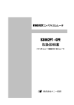
PARTS LIST / PD30X–X FLUID SECTION
FLUID SECTION SERVICE KITS (637303–XX)
L KITS INCLUDE: BALLS (See Ball Option, refer to -XX in chart below), DIAPHRAGMS (See Diaphragm Option, refer to -XX in
chart below), and items; 19, 70, 144, 175, (listed below) plus (174) and 94276 Lubriplate FML-2 grease (page 6).
SEAT OPTIONS PD30X-XXX-XXX
L ``19"
``21''
``21"
-XXX
SEAT (4)
[MTL]
-AXX
94104-A
[SP]
-GXX
94104-G
[G]
-HGX
94114
-HAX
94114
-HTX
94114
``19''
[MTL]
-XXX
SEAT (4)
-------
---
---
-KXX
94621-K
[K]
Y328-350
(4)
[T]
-------
---
---
-SGX
94113
[SS]
Y325-350
(8)
[B]
[SH]
Y325-350
(8)
[B]
-SAX
94113
[SS]
94115
(8)
[E]
[SH]
94115
(8)
[E]
-STX
94113
[SS]
Y328-350
(8)
[T]
[SH]
Y328-350
(8)
[T]
BALL OPTIONS
PD30X-XXX-XXX
L ``22" (3.25" dia.)
-XXX
L
GASKET
QTY
GASKET
BALL (4)
[MTL]
QTY
[MTL]
MATERIAL CODE
DIAPHRAGM OPTIONS
PD30X-XXX-XXX
L SERVICE KIT
[MTL]
-XXX
L
-XX = (Ball)
-XX = (Diaphragm)
*2+(,2+
2,! !/"-, 1%%*
- -..%/
!01 /-,
%-*!01
! !01%**-5 !/$ 1%%*
!,1-./%,%
1!(,*%00 1%%*
PTF E
``7" / ``8"
DIAPHRAGM (2)
[MTL]
-XAX
94103-A
[SP]
-XXA
637303-XA
94091-A
[SP]
-XGX
94103-G
[G]
-XXG
637303-XG
94091-G
[G]
-XTX
94103-T
[T]
-XXT
637303-XT
94090-T / 94110-A [T/SP]
CENTER SECTION PART OPTIONS PD30XITEM
QTY
PD30A-
PD30S-
PART NO.
[MTL]
PART NO.
[MTL]
(2)
66167
[SS]
66167
[SS]
32 Leg
(2)
94101-1
[C]
94101-2
[SS]
68 Air Cap
(1)
94030-1
[A]
94031-1
[SS]
69 Air Cap
(1)
94030-2
[A]
94031-2
[SS]
(2)
Y325-117d
[B]
Y325-118f
[B]
DESCRIPTION (SIZE IN INCHES)
5 Backup Washer
Ln175 ``O" Ring (3/32" x d1" o.d. / f1-1/16" o.d.)
MANIFOLD THREAD / FLUID CAP MATERIAL OPTIONS PD30X-XXXITEM DESCRIPTION
PD30X-XAX-
QTY
PART NO.
(2)
94096
15 Fluid Cap
(2)
60 Outlet Manifold
(1)
61 Inlet Manifold
(1)
6 Diaphragm Screw
u -/ +-$%*0 20% PD30X-XCX-
[MTL]
PD30X-XHX-
PD30X-XSX-
PART NO.
[MTL]
PART NO.
[MTL]
PART NO.
[MTL]
[A]
94094
[SS]
94690
[Ha]
94094
[SS]
94024
[A]
94106
[CI]
94693
[Ha]
94107
[SS]
94118-[u]
[A]
94105-[u]
[CI]
94692-[u]
[Ha]
94116-[u]
[SS]
94218-[u]
[A] 94305-[u]
[CI]
-/ +-$%*0 20% 94691-[u]
[Ha]
94216-[u]
[SS]
EXTERNAL HARDWARE OPTION PD30X-XXXPD30X-XXP-
PD30X-XXS-
ITEM DESCRIPTION (SIZE IN INCHES)
QTY
PART NO.
[MTL]
PART NO.
[MTL]
26 Screw (M12 x 1.75 - 6g x 45 mm)
(28)
94412-1
[C]
94412-2
[SS]
COMMON PARTS
ITEM
DESCRIPTION (Size in Inches)
1 Rod
43 Ground Lug
Ln70
Gasket
QTY
PART NO.
[MTL]
ITEM
DESCRIPTION (Size In Inches)
QTY
PART NO.
131 Screw (M10 x 1.5 - 6g x 120 mm)
(4)
94531
[C]
``U" Cup (3/16" x 1-3/8" o.d.)
(2)
Y186-51
[B]
Gasket (.406" i.d. x .031" thick)
(4)
94098
[Co]
(1)
94093
[C]
(1)
93004
[Co]
Ln144
(2)
94100
[B]
n180
[MTL]
V +!/1 !/10 )%%. 1'%0% (1%+0 -, '!,$ (, !$$(1(-, 1- 1'% %/3(#% (10 &-/ &!01 /%.!(/ !,$ /%$2#1(-, -& $-4, 1(+%
PAGE 4 OF 8
PD30X-X
PARTS LIST / PD30X–X FLUID SECTION
FOR THE
AIR MOTOR SECTION
SEE PAGES 6 & 7
COLOR CODE
26 ,G
60
DIAPHRAGM BALL
MATERIAL
COLOR
SEAT
PTFE
22
19zk
68
21
19z=k
70 k
1
69
5
144 k
7
6,
15
g
43
175 k
22
19z=k
21
180
131 x
19zk
26 ,G
61
FIGURE 1
32
. TORQUE REQUIREMENTS ,
VIEW OF TWO PIECE PTFE DIAPHRAGM
SANTOPRENE
8
7 PTFE
NOTE: DO NOT OVERTIGHTEN FASTENERS
ALL FASTENERS ARE METRIC
(6) Diaphragm Screw 60 - 70 ft lbs (81.4 - 94.9 Nm)
(26) Fluid Caps / Manifold Screw 60 - 70 ft lbs (81.4 - 94.9 Nm),
g Do not exceed 90 ft lbs (122 Nm) on (5) stud and apply Loctite
271 to threads.
G Apply anti-seize compound to threads when using
SS fasteners and stainless steel wet ends.
LUBRICATION / SEALANTS
k Apply Lubriplate FML-2 Grease to all
``O" rings, ``U" Cups & mating parts.
USED WITH -HXX, KXX & -SXX ONLY
USED WITH -HXX & -SXX ONLY
x Apply Loctite 242 to threads at assembly.
=
z
PD30X-X
Z -*%)&,! %+ .$%,! "(( #* ! )!,*(&!-' #*!+!
PAGE 5 OF 8
PARTS LIST / PD30X–X AIR SECTION
n Indicates parts included in 637302 Air Section Service Kit shown below and items (70), (144), (175) and (180) shown on page 4.
AIR MOTOR PARTS
ITEM
QTY
PART NO.
101 Center Body (PD30A- )
DESCRIPTION (Size in Inches)
(1)
94028
[A]
135 Valve Block (PD30A- )
(1)
94032
[A]
Center Body (PD30S- )
(1)
94109
[SS]
Valve Block (PD30S- )
(1)
94318
[SS]
103 Bushing
(1)
94092
[D]
(1)
94033
[D]
107 Inlet Plug
(1)
94034
[C]
n 146 ``O" Ring z (3/32" x 1-1/16" o.d.)
(1)
Y325-118
[B]
109 Piston
(1)
92011
[D]
n 147 ``O" Ring z (1/8" x 1/2" o.d.) Also #174
(2)
Y325-202
[B]
n 110 ``U" Cup (1-3/8" o.d.) (Also Item #144)
QTY
PART NO.
[MTL]
ITEM
DESCRIPTION (Size In Inches)
136 Piston Plug
(1)
Y186-51
[B]
n 166 Track Gasket D
(1)
94026
[B]
111 Spool (PD30A- )
(1)
92005
[A]
n 167 Pilot Piston (includes 168 and 169)
(1)
67164
[D]
Spool (PD30S- )
(1)
93047
[C]
168 ``O" Ring (3/32" x 5/8" o.d.)
(2)
94433
[U]
(5)
92877
[Z]
169 ``U" Cup (1/8" x 7/8" o.d.)
(1)
Y240-9
[B]
n 113 ``O" Ring (small) (1/8" x 1-1/4" o.d.)
(5)
Y325-214
[B]
170 Piston Sleeve
(1)
94081
[Br]
n 114 ``O" Ring (large) (3/32" x 1-9/16" o.d.)
(7)
Y325-126
[B]
n 171 ``O" Ring (3/32" x 1-1/8" o.d.)
(1)
Y325-119
[B]
V 115 Spacer
(4)
92876
[Z]
n 172 ``O" Ring (1/16" x 1-1/8" o.d.)
(1)
Y325-22
[B]
116 Spacer
(1)
94027
[A]
n 173 ``O" Ring (1/16" x 1-3/8" o.d.)
(2)
Y325-26
[B]
118 Actuator Pin (.250" x 2.276")
(2)
94083
[SS]
Ln174 ``O" Ring (1/8" x 1/2" o.d.)
(2)
Y325-202
[B]
121 Sleeve
(2)
94084
[D]
n 176 Diaphragm (Check Valve)
(2)
94102
[U]
(1)
94099
[B]
n 177 Retaining Ring (1.804" dia.)
(1)
Y147-16-C
[C]
133 Lockwasher (1/4") (PD30A- )
(3)
Y117-416-C
[C]
(4)
Y178-56-S
[SS]
Lockwasher (1/4") (PD30S- )
(3)
Y14-416-T
[SS]
(1)
94276
134 Screw (M6 x 1.0 x 16 mm) (PD30A- )
(4)
96721030
[C]
Lubriplate Grease Packets (10)
Screw (M6 x 1.0 x 16 mm) (PD30S- )
(4)
96720081
[SS]
z Used on Stainless Steel models (PD30S- ) only.
112 Washer (1.556" o.d.)
n 132 Gasket (Valve Body)
181 Roll Pin z (.156" o.d. x 3/4" long)
LEn Lubriplate FML-2 Grease
D
Service is divided into two parts - 1.Pilot Valve, 2.Major Valve.
GENERALREASSEMBLY NOTES:
S 4= :?:= $0.?4:9 $0=A4.0 4> .:9?49@0/ 1=:8 7@4/ $0.?4:9 =0;,4=
S 9>;0.? ,9/ =0;7,.0 :7/ ;,=?> B4?3 90B ;,=?> ,> 90.0>>,=D ::6 1:=
/00; >.=,?.30> :9 80?,774. >@=1,.0> ,9/ 94.6> := .@?> 49 ++! =492>
%,60 ;=0.,@?4:9> ?: ;=0A09? .@??492 ++! =492> @;:9 49>?,77,?4:9
@-=4.,?0 ++! =492> B4?3 @-=4;7,?0 =0,>0
: 9:? :A0=?423?09 1,>?090=> =010= ?: ?:=<@0 >;0.414.,?4:9 -7:.6 :9 A40B
#0?:=<@0 1,>?090=> 1:77:B492 =0>?,=?
$#' %!!$ %: ,4/ 49 ?30 49>?,77,?4:9 :1 ++! =492> :9?:
?30 ;47:? ;4>?:9 @>0 %::7 % ,A,47,-70 1=:8 =:
PILOT VALVE DISASSEMBLY
7423? ?,; :9 >3:@7/ 0C;:>0 ?30 :;;:>4?0 >700A0 ;47:? ;4>?:9 ,9/ :?30= ;,=?>
#08:A0 >700A0 49>;0.? 4990= -:=0 :1 >700A0 1:= /,8,20
PILOT VALVE REASSEMBLY
70,9 ,9/ 7@-=4.,?0 ;,=?> 9:? -0492 =0;7,.0/ 1=:8 >0=A4.0 64?
9>?,77 90B ++! =492> =0;7,.0 >700A0
9>?,77 90B ++! =492> >0,7 :?0 ?30 74; /4=0.?4:9 @-=4F
.,?0 ,9/ =0;7,.0 #0,>>08-70 =08,49492 ;,=?> =0;7,.0 ,9/ ++! =492>
637308
Used on Aluminum models (PD30A- ) only.
AIR MOTOR SECTION SERVICE
S
S
S
S
S
[MTL]
%# !
)* )* )=* )* 7@849@8
@9, ++ =,>>
,=-:9 $?007
)* ,>? =:9
)* .0?,7
)$"* $,9?:;=090
)$$* $?,4970>> $?007
)&* ":7D@=0?3,90
)(* (49.
MAJOR VALVE DISASSEMBLY
#08:A0 A,7A0 -7:.6 0C;:>492 2,>60?> ,9/ .30.6>
#08:A0 >9,; =492 ,9/ 4970? ;7@2
!9 ?30 >4/0 :;;:>4?0 ?30 ,4= 4970? ;@>3 :9 ?30 4990= /4,80?0= >;::7 %34> B477 1:=.0 ?30 ;4>?:9 ;7@2 ,9/ ;4>?:9 :@?
:9?49@0 ;@>3492 ?30 >;::7 ,9/ =08:A0 30.6 1:= >.=,?.30>
:= 2:@20>
#08:A0 ?30 ,5:= ',7A0 ;,=?> MAJOR VALVE REASSEMBLY
#0;7,.0 B,>30= ++! =492 ++! =492 :9?: >;,.0= ,9/ 49>0=? 0?. :9?49@0 ?34> =:@?490 ?: -@47/ ?30 8,5:= A,7A0
>?,.6
NOTE: Be careful to orient spacer legs away from blocking interĆ
nal ports.
#0;7,.0 >;::7 :9 ;7@2 >0,7 :9 ;4>?:9 ,9/
=0;7,.0 ;7@2 ,9/ >9,; =492
V ++$8,=? ",=?> 00; ?30>0 4?08> :9 3,9/ 49 ,//4?4:9 ?: ?30 $0=A4.0 4?> 1:= 1,>? =0;,4= ,9/ =0/@.?4:9 :1 /:B9 ?480
PAGE 6 OF 8
PD30X-X
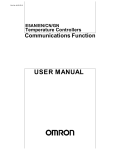
PARTS LIST / PD30X–X AIR SECTION
MAJOR VALVE CROSS SECTION DETAIL
109 110 112 114 113 115
111 116
174 FIGURE 3
118
121
173 169 167
168 PILOT VALVE
PART GROUP
172 171 173 121 118
174 170
177
136
114 109
110 Substitute these
``O" rings for ``166''
on models PD30S.
111
147 146 176
166 132 135
134
103
133
101
FIGURE 2
112
113 114 181 (PD30S- only)
115
Optional 94117 Muffler
MAJOR VALVE
See cross section
detail figure 3 above.
113 114 116
114 107
IMPORTANT
BE CERTAIN TO ORIENT (115) SPACER LEGS
AWAY FROM BLOCKING INTERNAL PORTS
WHEN REASSEMBLING AIR SECTION.
TORQUE REQUIREMENTS NOTE: DO NOT OVERTIGHTEN FASTENERS
ALL FASTENERS ARE METRIC
Torque (134) Screw to 40 - 50 in. lbs (4.5 - 5.6 Nm)
#% ) %) &! & ) &$%' + * " (& ' # #*"
) &! (!$ # &
'!& " (
PD30X-X
LUBRICATION / SEALANTS
Apply Lubriplate FML-2 Grease to ``O" rings, ``U" Cups
& mating parts.
PAGE 7 OF 8
TROUBLE SHOOTING
!64+9*8 +07*/(6.,+ -642 ,</(978 4981,8
#% $%! %($'(%
''"&& # $%! "('
4; 498598 :4192, ,66(80* -14; 46 34 -14;
% &($$ ,
#% $ ( #(' ' #&
#% " %&'%') #(' ' !'% #&
#% " %&'%') #% # $& " ' !'% #&
#% $(!$ )''#" &('#" $$ &#( &- ' &' &
% & ' " ' '% !'% # ' $(!$ #% $%#$% #* )&#&', (& % " $(!$ ('#" #& !(&' "#"# .
$&" ',$ $ # $( " )((!
#"'& #" ' " ' !"# & " &('#" #""'#"&
& !(&' % ''
"&$' ' $(!$ #% &# #'& # " ' $%! !.
% #% ' &' %
06 )9))1,7 03 564+9*8 +07*/(6.,
#""'#"& # &('#" $ (!"
%"& '*" "' !"# " ( $&
''"&& # $%! "('
4846 )14;7 (06 46 78(117
) ) #% ! #% *%
#% %&'%'#"& " ) ) +(&'
DIMENSIONAL DATA
!"&#"& &#*" % #% %%" #" , ', % &$ , " "& " ! !'%& !!
22
22
22
$"
%$$
!$
!&&&&&&
#!
!&&&&&&
22
" $
!$
22
488,+ 103,7 7/4; 458043(1
9--1,6 72
22
# $
22
22
$"
$
!$ </(978 5468
22
22
!$ ## "' 06103, 433,*8043 08
%" ! ! !&&


![[S3062PT-CPE] User`s Manual(Third Edition): CPE62PUE](http://vs1.manualzilla.com/store/data/005693507_1-69a1045bbc5cf41449359b406d2a53f2-150x150.png)
![[S3062PT-CPE-2] User`s Manual(First Edition): CPE62PSUE_2](http://vs1.manualzilla.com/store/data/005668190_1-0d028d6af383e5d06430420ca44dee4c-150x150.png)