1
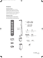
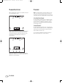
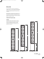
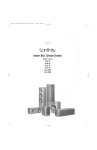
INFP1595Sat4000-OM
10/18/04
2:41 PM
Page 1
TSS-4000
TOTAL SPEAKER SOLUTIONS
TSS-SAT4000
Owner’s Guide
INFP1595Sat4000-OM
10/18/04
2:41 PM
Page 2
TSS-SAT4000 OWNER’S GUIDE
Table of Contents
3
Introduction
4
Planning Your System
4
Placement
5
Installation
5
Tabletop/Shelf Placement Assembly
8
Wall-Mounting the TSS-SAT4000 Using
the Included Wall Bracket
9
10
2
TSS-SAT4000
Wiring the Speaker
Specifications
INFP1595Sat4000-OM
10/18/04
2:41 PM
Page 3
INTRODUCTION
Infinity Total Solutions™
Infinity Total Solutions continues Infinity’s longstanding
commitment to accurate sound reproduction. Our proprietary
Metal Matrix Diaphragm™ (MMD®) drivers, precision dividing
networks and rigid, well-braced enclosures combine to deliver
uncompromised performance in any stereo or multichannel home
theater system. In addition, these speakers are magnetically
shielded for safe placement adjacent to a television.
Unpacking the Speaker
Carefully unpack the speaker. If you suspect damage from
transit, report it immediately to your dealer and/or delivery
service. Keep the shipping carton and packing materials for
future use. Open the package and verify the following contents:
Part A
Part B
(2) Wall-Mount End Caps
(attached to satellite)
(1) Wall Bracket
With Wall
Bracket Cover
(1) Flat-Head Phillips
Screw
1/4-20 x 1-1/4"
(1) Pan-Head Phillips Screw
1/4-20 x 3/4"
(6) Flat-Head Phillips (2) Pan-Head Phillips Screws
1/4-20 x 1"
Screws
1/4-20 x 7/8"
(1) Satellite
Speaker
(1) Table Stand Plate
(1) Medium
Collar
(3) 1/4-20
Flat Washers
(3) 1/4-20 Nuts
(1) Bottom Foot
(1) Allen
Wrench
(1) Small Collar
(1) Large
Collar
TSS-SAT4000
3
INFP1595Sat4000-OM
10/18/04
2:41 PM
Page 4
PLANNING YOUR SYSTEM
PLACEMENT
Before deciding where to best place your speakers, survey your
room and study Figures 1 and 2.
NOTE: The satellite speakers can be placed directly on a shelf
using one of the three included shelf stands, or mounted on a
wall using the included wall brackets. Optional floor stands and
in-wall recess kits are also available. Please contact your dealer.
Left
Front
Channel
Center
Channel
(above or below TV)
Right
Front
Channel
Subwoofer
Left and Right Front Channels
For left and right front channels, place one satellite to the left
and another to the right of the television, as shown in Figure 1.
Since the speakers are magnetically shielded, you can place
them very close to the TV without worrying about the magnetic
field distorting the picture.
Surround Channels
Couch
Left
Surround
Channel
Right
Surround
Channel
Figure 1. In this overhead view of a typical 5-channel installation,
satellite speakers are used to reproduce sound for the front
and surround channels.The center channel reproduces sound
and dialogue.The powered subwoofer provides bass for
effects and music.
Left
Front
Channel
Center
Channel
(above or below TV)
Right
Front
Subwoofer
Channel
Couch
Left
Surround
Channel
Left
Rear
Channel
Center
Rear
Channel
Right
Rear
Channel
Right
Surround
Channel
Figure 2.This overhead view shows a typical home theater plan.
Left/right rear channels are for a 7-channel system. Center rear
channel is for a 6-channel system.
4
TSS-SAT4000
For left and right surround channels, place one speaker on the
left and another on the right, to the side of or slightly behind the
listening area.The surround speakers should be mounted at a
height of between 4 feet and 7 feet.
In 6- or 7-channel configurations, place the rear channel(s)
behind the listening position, as shown in Figure 2.
INFP1595Sat4000-OM
10/18/04
2:41 PM
Page 5
INSTALLATION
Please read through this owner’s guide completely before
attempting to install or connect the speakers. We understand that
you may be anxious to play your new system, so we have made
every effort to simplify the installation and connections of the
TSS-SAT4000.
Before proceeding, you should decide how you would like to install
the TSS-SAT4000.The TSS-SAT4000 may be mounted on the
included shelf stands; mounted on the wall using the included wall
brackets; recessed in the wall using an optional flush-mount kit; or
mounted to our optional floor stands.
Tabletop/Shelf Placement Assembly
Step One
Choose one of the three shelf stands on which to mount the
satellite. If you decide to place the stand next to a television,
the television’s height should be taken into consideration.
If you choose the shortest stand, follow steps two to four
on page 6. If you choose either of the taller stands, follow
steps two to five on page 7.
30-1/2"
27"
23-3/8"
8"
4"
7/8"
Small
Medium
Large
TSS-SAT4000
5
INFP1595Sat4000-OM
10/18/04
2:41 PM
Page 6
Step Two
Step Three
For Small Table Stand Assembly
Using the included Allen wrench, remove the bottom end cap
of the speaker by unscrewing the single center screw on bottom.
For Small Table Stand Assembly
Assemble the table stand plate, the small section and the foot.
Place three nuts (provided) in base of foot and secure them
in place by three screws (provided) through the top of the
table stand plate.
(3) 1/4-20 x 7/8"
Flat-Head Screws
Table Stand Plate
Satellite Speaker
End Cap
Small Section/Collar
Infinity Logo
Foot
1/4-20 x 3/4"
Screw
(3) 1/4-20 Nuts
NOTE: The bottom is the
side closest to the Infinity
logo on the front grille
and the speaker
connections on the rear.
Step Four
For Small Table Stand Assembly
Run speaker wire through base, and screw foot assembly to
speaker assembly.
Speaker Wire
1/4-20 x 1-1/4"
Flat-Head Screw
6
TSS-SAT4000
INFP1595Sat4000-OM
10/18/04
2:42 PM
Page 7
Step Two
Step Four
For Medium and Large Table Stand Assembly
Using the included Allen wrench, remove the bottom end cap
of the speaker by unscrewing the single center screw on bottom.
For Medium and Large Table Stand Assembly
Use screw and washer to attach medium
or large base assembly to the
speaker assembly, as shown.
Satellite Speaker
End Cap
Infinity Logo
Flat Washer
NOTE: The bottom is the
side closest to the Infinity
logo on the front grille
and the speaker
connections on the rear.
1/4-20 x 1"
Pan-Head Screw
1/4-20 x 3/4"
Screw
Flat Washers
1/4-20 x 3/4"
Pan-Head Screw
1/4-20 x 1"
Pan-Head Screw
Step Five
For Medium and Large Table Stand Assembly
Run speaker wire through table stand plate. Use three screws
(provided) to attach plate to bottom of base assembly.
Step Three
For Medium and Large Table Stand Assembly
Run speaker wire through collar. Using three screws, attach table
stand plate to the medium or large section as shown.
(3) 1/4-20 x 7/8"
Flat-Head Screws
Speaker Wire
Speaker Wire
(3) 1/4-20 x 7/8"
Flat-Head Screws
TSS-SAT4000
7
INFP1595Sat4000-OM
10/18/04
2:42 PM
Page 8
Wall-Mounting the SAT-4000 Using the Included
Wall Bracket
The customer is responsible for proper selection and use of
mounting hardware, and for correctly and safely wall-mounting
the speakers.
Step Four
Using the included Allen wrench, remove the bottom end cap
of the speaker by unscrewing the single center screw on bottom.
End Cap
Step One
Remove the wall-bracket
cover by removing the four
wall bracket screws on
the ends as shown.
Satellite Speaker
End Cap
Infinity Logo
Step Two
Run the speaker wire behind the
wall bracket and out the hole at
the bottom. After deciding where
to place the satellite speaker,
attach the wall bracket (in a
vertical position) to the wall
using the appropriate screws
and anchors.
Wall Bracket
Mounting
Screws and
Anchors
Not Included
Bottom Hole
NOTE: The bottom is the
side closest to the Infinity
logo on the front grille
and the speaker
connections on the rear.
1/4-20 x 3/4"
Screw
Step Five
Connect the wires (page 9).
Replace the end caps while
capturing the wall bracket in
between parts A and B and
securing it in place.Tighten
until snug.
Step Three
Run the speaker wires out
through the bottom hole of the
wall bracket cover. Resecure
in place as shown with four
of the wall bracket screws.
Wall-Mount
End Cap A
Wall-Mount
End Cap B
8
TSS-SAT4000
INFP1595Sat4000-OM
10/18/04
2:42 PM
Page 9
Step Six
The wall-bracket design allows for rotation of the speakers
at angles up to 30 degrees of center. Position the speakers
so they face toward the primary listening position, before
fully tightening.
2
1
–
WIRING THE SPEAKER
After placing the speaker, you are ready to connect it to your
system. First, turn off all audio-system power. Use high-quality
speaker wire to make the connections. Consult the owner’s
manuals, included with your amplifier or receiver, for connection
and operation procedures.
Surround Modes
When using the TSS-SAT4000 in a Dolby* Digital or DTS® home
theater system, make sure the receiver’s/processor’s speaker
modes are set to “Small.”
+
Figure 3.This example shows how to connect bare wires to the
terminals. Banana plugs may also be inserted directly into the
rear of the connector.
1 Loosen the terminals.
2 Insert bare ends; tighten terminals.
CARE OF YOUR SPEAKER SYSTEM
When needed, use a soft cloth to remove any fingerprints or
to wipe off dust. Do not use any cleaning products or polished.
Clean the grille by gentle vacuuming.
Wiring and Polarity
The TSS-SAT4000 speaker has gold-plated terminals that
can accept bare wire.To ensure proper polarity, connect each
+ terminal on the back of the amplifier or receiver to the
respective + (red) terminal on each speaker, as shown in
Figure 3. Connect the – (black) terminals in a similar way.
See the owner’s manuals that were included with your amplifier
or receiver to confirm connection procedures.
Important!
Do not reverse polarities (i.e., + to – or – to +) when making
connections. Doing so will degrade the imaging and bass
response of the home theater system.
After correctly placing and wiring the TSS-SAT4000 and
the rest of your speaker system, adjust the levels for all of
the channels as recommended by the manufacturer of your
receiver/processor.
TSS-SAT4000
9
INFP1595Sat4000-OM
10/18/04
2:42 PM
Page 10
SPECIFICATIONS
TSS-SAT4000
OPTIONAL ACCESSORIES
Frequency Response
120Hz – 20kHz (±3dB)
Nominal Impedance
8 ohms
Sensitivity
(2.83V @ 1m)
89dB
Recommended Amplifier
Power Range
10 – 150 watts
Crossover Frequencies
1,000Hz, 3,800Hz; 24dB/octave
Low-Frequency Drivers
(4) 3-1/2" (89mm) MMD,®
magnetically shielded
Mid-Frequency Drivers
(2) 3-1/2" (89mm) MMD,
magnetically shielded
High-Frequency Driver
3/4" (19mm) MMD,
magnetically shielded
Dimensions (H x W x D)
23" x 4-1/8" x 4-3/8"
(584mm x 105mm x 111mm)
Weight
12.7 lb (5.8kg)
FMK-4000
STAND-4000
Flush-Mount Kit for TSS-SAT4000
Floor Stand for TSS-SAT4000
Infinity continually strives to update and improve existing products, as well as create new ones.
The specifications and construction details in this and related Infinity publications are therefore
subject to change without notice.
Declaration of Conformity
We, Harman Consumer International
2, route de Tours
72500 Chateau-du-Loir
France
declare in own responsibility that the products
described in this owner’s manual are in compliance
with technical standards:
EN 61000-6-3:2001
EN 61000-6-1:2001
Robin Marshall
Harman Consumer International
Chateau-du-Loir, France 10/04
10
TSS-SAT4000
INFP1595Sat4000-OM
10/18/04
2:42 PM
Page 11
NOTES
TSS-SAT4000
11
INFP1595Sat4000-OM
10/18/04
2:41 PM
Page 12
© 2004 Harman International Industries, Incorporated
Infinity Systems, 250 Crossways Park Drive, Woodbury, NY 11797 USA 516.674.4INF (USA only) www.infinitysystems.com
* Trademarks of Dolby Laboratories. DTS is a registered trademark of Digital Theater Systems, Inc.
Infinity and MMD are registered trademarks, and Total Solutions and Metal Matrix Diaphragm are trademarks, of Harman International Industries, Incorporated. Part No. 400-OMSAT 10/04