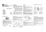
1
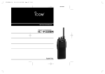
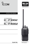
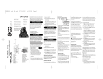
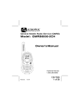
INSTRUCTION MANUAL
UHF GMRS TRANSCEIVER
iF21GM
This device complies with Part 15 of the FCC rules. Operation is subject to the following two conditions: (1) This device may not cause harmful interference, and (2) this
device must accept any interference received, including interference that may cause undesired operation.
SAFETY TRAINING INFORMATION
Your Icom radio generates RF electromagnetic
energy during transmit mode. This radio is designed for and classified as “Occupational Use
Only”, meaning it must be used only during the
W ARN ING
course of employment by individuals aware of the
hazards, and the ways to minimize such hazards.
This radio is NOT intended for use by the “General Population” in an uncontrolled environment.
This radio has been tested and complies with the FCC RF exposure limits for “Occupational Use Only”. In addition, your Icom radio
complies with the following Standards and Guidelines with regard to
RF energy and electromagnetic energy levels and evaluation of
such levels for exposure to humans:
• FCC OET Bulletin 65 Edition 97-01 Supplement C, Evaluating
Compliance with FCC Guidelines for Human Exposure to Radio
Frequency Electromagnetic Fields.
• American National Standards Institute (C95.1 – 1992), IEEE Standard for Safety Levels with Respect to Human Exposure to Radio
Frequency Electromagnetic Fields, 3 kHz to 300 GHz.
• American National Standards Institute (C95.3 – 1992), IEEE Recommended Practice for the Measurement of Potentially Hazardous
Electromagnetic Fields – RF and Microwave.
C AU TIO N
To ensure that your exposure to RF electromagnetic energy is within the FCC allowable limits for
occupational use, always adhere to the following
guidelines:
• DO NOT operate the radio without a proper antenna attached, as
this may damage the radio and may also cause you to exceed FCC
RF exposure limits. A proper antenna is the antenna supplied with
i
this radio by the manufacturer or an antenna specifically authorized
by the manufacturer for use with this radio.
• DO NOT transmit for more than 50% of total radio use time (“50%
duty cycle”). Transmitting more than 50% of the time can cause
FCC RF exposure compliance requirements to be exceeded. The
radio is transmitting when the “TX indicator” lights red. You can
cause the radio to transmit by pressing the “PTT” switch.
• ALWAYS use Icom authorized accessories (antennas, batteries,
belt clips, speaker/mics, etc). Use of unauthorized accessories can
cause the FCC RF exposure compliance requirements to be exceeded.
• ALWAYS keep the antenna at least 2.5 cm (1 inch) away from the
body when transmitting and only use the Icom belt-clips, listed in p. 22,
when attaching the radio to your belt, etc., to ensure FCC RF exposure compliance requirements are not exceeded. To provide the
recipients of your transmission the best sound quality, hold the antenna at least 5 cm (2 inches) from your mouth, and slightly off to
one side.
The information listed above provides the user with the information
needed to make him or her aware of RF exposure, and what to do to
assure that this radio operates within the FCC RF exposure limits of this
radio.
Electromagnetic Interference/Compatibility
During transmissions, your Icom radio generates RF energy that
can possibly cause interference with other devices or systems. To
avoid such interference, turn off the radio in areas where signs are
posted to do so. DO NOT operate the transmitter in areas that are
sensitive to electromagnetic radiation such as hospitals, aircraft,
and blasting sites.
ii
Your Icom F21GM operates on GMRS frequencies (Plus 7
channels shared with FRS ).
GENERAL MOBILE RADIO SERVICE (GMRS)
GMRS is a two-way personal radio service available to an individual
(one man or one woman) to facilitate the activities of the individual's immediate family members. GMRS is not authorized for business uses.
Users must cooperate in the selection and use of channels to make
the most effective use of them and reduce the possibility of interference. Channel 9 –15 are shared with FRS channels. You can
communicate with any FRS radios on these 7 channels. FRS is a
UHF two-way voice communication service for family, friends and
associates to communicate among themselves within their neighbourhood and while on group outings. Eight GMRS channels are
authorized for repeater operation*.
You must obtain a license for a GMRS system. Application is made
on FCC Form 605 or on line at http://www.fcc.gov/wtb/uls. As of
January, 2001, the license fee is $85 for a 5-year term. Schedule F
of the form permits immediate temporary operation during the application process. Form 605 and Form 159 remittance fee advice
are available for downloading at http://www.fcc.gov/formpage.html.
Applications may be mailed to Federal Communications Commission, Wireless Bureau Applications, PO Box 358245, Pittsburgh, PA
15251-5245
Call 1-800-418 FORM to have the forms mailed to you, or call 1202-418-0177 from your fax machine to have them faxed to you on
the FCC Fax-On-Demand system. For assistance completing the
forms call 1-800-CALL-FCC.
*Repeater use may require a subscription.
iii
iv
FOREWORD
Thank you for purchasing the IC-F21GM FM transceiver.
READ ALL INSTRUCTIONS carefully and completely before using
the transceiver.
SAVE THIS INSTRUCTION MANUAL–This instruction manual
contains important operating instructions for the transceiver.
IMPORTANT
R CAUTION! NEVER hold the transceiver so that the antenna is
very close to, or touching exposed parts of the body, especially the
face or eyes, while transmitting. The transceiver will perform best if
the microphone is 2 to 4 in. (5 to 10 cm) away from the lips and the
transceiver is vertical.
R CAUTION! NEVER operate the transceiver with a headset or
other audio accessories at high volume levels.
R CAUTION! NEVER short the terminals of the battery pack.
DO NOT push the PTT when not actually desiring to transmit.
AVOID using or placing the transceiver in direct sunlight or in areas
with temperatures below –22°F (–30°C) or above +140°F (+60°C).
DO NOT modify the transceiver for any reason.
KEEP the transceiver from the heavy rain, and Never immerse it in
water. The transceiver construction is water resistant, not waterproof.
The use of non-Icom battery packs/chargers may impair transceiver
performance and invalidate the warranty.
FCC caution: Changes or modifications to this transceiver, not
expressly approved by Icom Inc., could void your authority to operate this transceiver under FCC regulations.
v
TABLE OF CONTENTS
SAFETY TRAINING INFORMATION . . . . . . . . . . . . . . . . . . . .i-ii
ABOUT GMRS . . . . . . . . . . . . . . . . . . . . . . . . . . . . . . . . . . . . .iii
FOREWORD . . . . . . . . . . . . . . . . . . . . . . . . . . . . . . . . . . . . . . .v
IMPORTANT . . . . . . . . . . . . . . . . . . . . . . . . . . . . . . . . . . . . . . .v
TABLE OF CONTENTS . . . . . . . . . . . . . . . . . . . . . . . . . . . . . .vi
1 PANEL DESCRIPTION . . . . . . . . . . . . . . . . . . . . . . . . . . .1–3
‘ Switches, controls, keys and connectors . . . . . . . . . . . .1–2
‘ LED indicator . . . . . . . . . . . . . . . . . . . . . . . . . . . . . . . . . . .3
2 ACCESSORIES . . . . . . . . . . . . . . . . . . . . . . . . . . . . . . . . . . .4
3 BATTERY PACKS . . . . . . . . . . . . . . . . . . . . . . . . . . . . . .5–11
‘ Battery pack replacement . . . . . . . . . . . . . . . . . . . . . . . . .5
‘ Battery cautions . . . . . . . . . . . . . . . . . . . . . . . . . . . . . . . . .6
‘ Battery charging . . . . . . . . . . . . . . . . . . . . . . . . . . . . . . .7-9
‘ Charging NOTE . . . . . . . . . . . . . . . . . . . . . . . . . . . . . . .10
‘ Battery case (Option) . . . . . . . . . . . . . . . . . . . . . . . . . . .11
4 SET MODE . . . . . . . . . . . . . . . . . . . . . . . . . . . . . . . . . . .12-19
‘ Set mode . . . . . . . . . . . . . . . . . . . . . . . . . . . . . . . . . . . . .12
5 OPERATION . . . . . . . . . . . . . . . . . . . . . . . . . . . . . . . . . .20-22
‘ Receiving and transmitting . . . . . . . . . . . . . . . . . . . . . . .20
‘ Setting squelch level . . . . . . . . . . . . . . . . . . . . . . . . . . . .22
‘ Auto scan function . . . . . . . . . . . . . . . . . . . . . . . . . . . . . .22
‘ Wide/Narrow selection . . . . . . . . . . . . . . . . . . . . . . . . . . .22
6 OPTION . . . . . . . . . . . . . . . . . . . . . . . . . . . . . . . . . . . . . .23-24
Icom, Icom Inc. and the
logo are registered trademarks of
Icom Incorporated (Japan) in the United states, the United Kingdom, Germany, France, Spain, Russia and/or other countries.
vi
1
PANEL DESCRIPTION
‘ Switches, controls, keys and
connectors
q CH1↔CH16
y
w
u
e
Speaker
i
t
SP MIC
r
Mic
• HM-75A (OPTION)
Mic A
Mic UP
Mic B
Mic Down
1
PANEL DESCRIPTION
1
q CHANNEL SELECTOR/SW [CH] (p. 14)
Turn to select CH1 to CH16.
w VOLUME CONTROL [OFF/VOL]
Turns power ON and adjusts the audio level.
e MONITOR (Audi) key [MONI] (p. 21)
• Push and hold to open the noise/tone squelch.
• Push to turn the noise/tone squelch ON.
r PTT SWITCH [PTT]
Push and hold to transmit; release to receive.
t WIDE/NARROW KEY [W/N] (p. 22)
• Push to select Wide FM mode.
• Push and hold to select Narrow FM mode.
y ANTENNA CONNECTOR
Connects the supplied antenna.
u TX/RX INDICATOR LED (p. 3)
• Lights red while transmitting.
• Lights green while receiving a signal, or squelch is open.
i [SP]/[MIC] JACK
Connects optional speaker-microphone.
D HM-75A Speaker Microphone key reference (OPTION)*
Mic Up
Push and hold to open the noise/tone squelch.
Mic Down
Same as [W/N] key. (p. 22)
Mic A
Push to start/stop scan function. (P. 22)
Mic B
Push several times to select output power; Low1,
Low2 and High. (p. 13)
*These functions are available when the optional Speaker/Mic. is connected.
2
1
PANEL DESCRIPTION
‘ LED indicator
The TX/RX indicator LED indicates information in several ways as follows;
(Ref.; R=Red, G=Green)
• TX: Turns Red while transmitting a signal.
R
• RX: Turns Green while receiving a signal.
G
• Low BATT1: You should charge the battery. (blinks slowly)
R
R
• Low BATT2: You must charge the battery. (blinks fast)
R
R
R
R
• TX low BATT1: Low BATT1 was detected during TX mode.
R
R
• TX low BATT2: Low BATT2 was detected during TX mode.
R
R
R
R
• Auto scan: LED blinks during scan operation. (p. 22)
G
G
G
CAUTION:
• Low BATT3: If you did not charge the battery after Low BATT2
warning has appeared, the Low BATT3 warning beep emits for 15
sec. then the power turns OFF automatically.
3
ACCESSORIES
2
‘ Accessory attachment
D Supplied accessories
The transceiver comes supplied with the following accessories.
q Flexible antenna
q
w Belt clip
w
D Antenna
The antenna screws onto the transceiver as
illustrated at right.
D Belt clip
Attach the belt clip to the transceiver as illustrated below.
4
3
BATTERY PACKS
‘ Battery pack replacement
Before replacing the battery pack, the volume control MUST be rotated fully counterclockwise,
until a click is heard, to turn the
power OFF.
• Push the battery release forward, then pull the battery
pack upward with the transceiver facing you.
D BATTERY PACKS
Charging period
Battery
Voltage Capacity
pack
Operating
period*1
BC-146
BC-144,
BC-119 or
BC-121
12 hrs
1.5 hrs
8 hrs
18.5 hrs
2.0 hrs
11 hrs
6.5 hrs
1 hr
Battery case for AA
BP-208*2 (R6) × 6 alkaline
BP-209
7.2 V
BP-210
7.2 V
BP-222*3
7.2 V
1100
mAh
1650
mAh
600
mAh
5.5*3 hrs
*1 Operating periods are calculated under the following conditions;
Tx : Rx : standby =5 : 5 : 90
*1 Operating period depends on the alkaline cells used. (BP-208 only)
*2 Output power is automatically reduced to 1 W to retain sufficient power
in case of an emergency, etc.
*3 Operating period measured with the 2 W model.
5
BATTERY PACKS
3
‘ Battery cautions
• CAUTION! NEVER short the terminals of the battery pack (or
charging terminals of the transceiver). Also, current may flow into
nearby metal objects such as a necklace, so be careful when placing battery packs (or the transceiver) in handbags, etc.
Simply carrying with or placing near metal objects such as a necklace, etc. causes shorting. This will damage not only the battery
pack, but also the transceiver.
• NEVER incinerate used battery packs. Internal battery gas may
cause an explosion.
• NEVER immerse the battery pack in water. If the battery pack becomes wet, be sure to wipe it dry BEFORE attaching it to the
transceiver.
• Clean the battery terminals to avoid rust or miss contact.
• Keep battery contacts clean. It’s a good idea to clean battery terminals once a week.
If your battery pack seems to have no capacity even after being
charged, completely discharge them, then fully charge the battery
pack again. If the battery pack still does not retain a charge (or only
very little charge), a new battery pack must be purchased.
D Recycling information (U.S.A. only)
The battery (BP-209, BP-210 or BP-222) that you
have purchased is recyclable. At the end of its life,
under various state and local laws, it may be illegal
to dispose of this battery into the municipal waste
stream. Call 1-800-822-8837 for battery recycling
options in your area or contact your dealer.
6
3
BATTERY PACKS
‘ Battery charging
D Rapid charging with the BC-144+AD-99
The optional BC-144 provides rapid charging of optional battery
packs.
The following are additionally required:
• One AD-99 (depends on version.).
• An AC adaptor (may be supplied with the BC-144 depending on
version).
BP-209, BP-210
or BP-222 only
AC adaptor
BC-145A/E/V/UK
Check orientation.
Charging indicator
7
BATTERY PACKS
3
D Rapid charging with the BC-144+AD-99
Turn power OFF
BP-209, BP-210
or BP-222 attached
to the transceiver.
AC adaptor
BC-145A/E/V/UK
Check orientation
and the spacer combination as follows.
Charging indicator
D Spacer combination.
• Be sure to attach the
Check orientation
spacer (Spacer B/C) to
the adaptor (Spacer A)
and
Spacer A
with the orientation as illustrated in the diagram at
right.
Spacer B/C
• Attach
the
spacer
(Spacer B/C) to the adaptor with the orientation of the stamp “ ” pointing up.
NOTE: Push the notch carefully
when removing the spacer from the
adaptor.
8
3
BATTERY PACKS
D Rapid charging with the BC-121+AD-94 (#11)
The optional BC-121 allows up to 6 battery packs to be charged simultaneously. The following are additionally required.
• Six AD-94 (#11) (Some versions require additional AD-99s).
• An AC adaptor (may be supplied with the BC-121 depending on
version).
Turn power OFF.
AC adapter
(purchased
separately)
AD-99
RGER
I-CHA
MULT
Charge indicator
(each indicator functions independently)
D Regular charging with the BC-146
The optional BC-146 pro- Turn power OFF.
vides regular charging of
optional battery pack with/
without transceiver.
The following is additionally
required:
• An optional AC adaptor.
Check orientation
for correct charging. (Insert together with charging
adapter.)
(A charging spacer is supplied with BC-146.)
BC-146
9
BATTERY PACKS
3
‘ Charging NOTE
Prior to using the transceiver for the first time, the battery pack must
be fully charged for optimum life and operation.
• Recommended temperature range for charging:
+10°C to +40°C (50°F to 140°F).
• Use the supplied charger or optional charger (BC-119/BC-121/BC144 for rapid charging, BC-146 for regular charging) only. NEVER
use other manufacturers’ chargers.
The optional BP-209, BP-210 or BP-222 battery packs include
rechargeable Ni-Cd(Ni-MH: BP-210) batteries and can be charged
approx. 300 times. Charge the battery pack before first operating
the transceiver or when the battery pack becomes exhausted.
If you want to charge the battery pack more than 300 times, the following points should be observed:
• Avoid overcharging–batteries must be removed from the charger
to stop charging. Batteries should not be charged for more than
15 hours after the LED indicator turns green.
• Use the battery until it becomes almost completely exhausted
under normal conditions.
D Battery pack life
When the operating period becomes extremely short even after
charging the battery pack fully, a new battery pack is needed.
NOTE: The charger rapidly charges a battery pack to a specified level, not a completed level, to prevent overcharging. Leave
the battery pack in the charger for a few more hours (up to
15 hours; depending on battery condition) after the LED indicator turns green, to charge the battery completely.
10
3
BATTERY PACKS
‘ Battery case (Option)
When using a BP-208 OPTIONAL BATTERY CASE attached to the
transceiver, install 6 AA (R6) size alkaline batteries as illustrated
below.
NOTE: Output power is automatically reduced to 1 W to retain sufficient power in case of an emergency, etc.
D CAUTIONS
• Use ALKALINE batteries only.
• Make sure all battery cells are the same brand, type and capacity.
• Never mix old and new batteries.
Either of the above may cause a fire hazard or damage the
transceiver, if ignored.
• Never incinerate used battery cells since internal battery gas
may cause them to rupture.
• Never expose a detached battery case to water.
If the battery case gets wet, be sure to wipe it dry before using
it.
11
SET MODE
4
‘ Set mode
Set mode is used for programming infrequently changed values or
conditions of functions.
• All settings performed with [CH selector], [OFF/VOL], [MONI],
[PTT] and [W/N] keys.
D SELECTING
POWER
RF
OUTPUT
The RF output can be selected
from one of 3 modes. (p. 13)
D SETTING THE SIMPLEX/DUPLEX OPERATION
The Simplex/Duplex function
changes duplex operation to simplex operation. (pgs. 13–14)
[CH selector]
[OFF
/VOL]
[MONI]
[PTT]
[W/N]
D SETTING THE CTCSS TONE
FREQUENCY
CTCSS (Continuous Tone Coded Squelch System) encoder/decoder
are standard, providing quiet stand-by. (pgs. 15–16)
D CTCSS FIND
This transceiver can detect the CTCSS tone frequency in the received signal. (p. 19)
D SETTING THE DTCS CODE
DTCS (Digital Tone Coded Squelch system) encoder/decoder are
standard, providing quiet stand-by. (pgs. 17–18)
12
2
CHAPTER CONTINUED
D SELECTING RF OUTPUT POWER
The transceiver has 3 output power levels to suit your operating requirements. Low out put power settings during short-distance communications may reduce the possibility of interference to other
stations, and will reduce current consumption.
q While pushing and holding [PTT], [MONI], turn [OFF/VOL] to
power ON.
w Push [MONI] to toggle between Low1 (1 W ; Pi), Low2 (2 W ;
PiPi) and High (4 W ; PiPiPi).
e Turn the power OFF, and then ON again.
D SETTING THE SIMPLEX/DUPLEX OPERATION
The Simplex/Duplex function changes duplex channels to simplex
channels.
q While pushing and holding [PTT], [MONI], turn [OFF/VOL] to
power ON.
w Turn CH selector knob to select the desired channel.
e Push [W/N] to turn the simplex mode ON.
• A beep (Pi) is emitted.
or
e Push and hold [W/N] to turn the duplex mode ON.
• A long beep (Pii) is emitted.
r Turn the power OFF, and then ON again.
NOTE: Duplex mode is available between CH 1 to CH 8. (see
right.)
13
CHAPTER CONTINUED
2
• Frequency channel list
No. Rx/Tx Freq.*1
Tx Freq.*2
Wide/Narrow
1
462.5500
467.5500
Narrow
2
462.5750
467.5750
Narrow
3
462.6000
467.6000
Narrow
4
462.6250
467.6250
Narrow
5
462.6500
467.6500
Narrow
6
462.6750
467.6750
Narrow
7
462.7000
467.7000
Narrow
8
462.7250
467.7250
Narrow
9
462.5625
------
Narrow
10
462.5875
------
Narrow
11
462.6125
------
Narrow
12
462.6375
------
Narrow
13
462.6625
------
Narrow
14
462.6875
------
Narrow
15
462.7125
------
Narrow
16
Auto Scan
------
------
Note
White
Black
Orange
(Unit: MHz)
*1: Simplex operation/Duplex receive frequency
*2: Duplex transmit frequency
Wide/Narrow: Wide FM/Narrow FM (default)
14
4
SET MODE
D SETTING THE CTCSS TONE FREQUENCY
This transceiver is equipped with 52 CTCSS codes. (See right.)
CTCSS operation provides communication with silent standby since
you will only receive calls from group members using the same
CTCSS number.
You can assign different numbers to CH 1 to CH 15 independently.
q While pushing and holding [PTT], [MONI], [W/N], turn [OFF/VOL]
to power ON.
w Select the desired CH 1 to CH 15 that you want to assign the
CTCSS tone frequency to.
e Push and hold [MONI] until a beep (Pi) is emitted.
r Push [PTT] the necessary number of times to choose the 10 digit
of the desired channel from the channel list.
t Push [MONI].
• Confirmation beep is emitted. (See p. 17)
y Push [PTT] the necessary number of times to choose the 1 digit
of the desired channel from the frequency list.
u Push [MONI].
i Turn the power OFF, and then ON again.
[Example]
To assign No. 28 as CH1;
q While pushing and holding [PTT], [MONI] and [W/N], turn
[OFF/VOL] to power ON.
w Select the CH 1.
e Push and hold [MONI] until a beep (Pi) is emitted.
r Push [PTT] twice to choose the 10 digit of the desired channel.
t Push [MONI].
y Push [PTT] eight times to choose the 1 digit of the desired channel.
u Push [MONI].
i Turn the power OFF, and then ON again.
15
SET MODE
4
• CTCSS tone code list
No.
Freq.*
No.
Freq.*
No.
Freq.*
No.
Freq.*
0
OFF
16
107.2
32
171.3
48
233.6
1
67.0
17
110.9
33
173.8
49
241.8
2
69.3
18
114.8
34
177.3
50
250.3
3
71.0
19
118.8
35
179.9
51
254.1
4
71.9
20
123.0
36
183.5
52
270.4
5
74.4
21
127.3
37
186.2
6
77.0
22
131.8
38
189.9
7
79.7
23
136.5
39
192.8
8
82.5
24
141.3
40
196.6
9
85.4
25
146.2
41
199.5
10
88.5
26
151.4
42
203.5
11
91.5
27
156.7
43
205.5
12
94.8
28
159.8
44
210.7
13
97.4
29
162.2
45
218.1
14
100.0
30
165.5
46
225.7
15
103.5
31
167.9
47
229.1
(Unit: Hz)
: EIA/TIA standard code (Recommended to use these.)
16
4
SET MODE
D SETTING THE CTCSS TONE FREQUENCY (continued)
• CTCSS confirmation beep
Push [PTT]
no
1 (Once)
2 (Twice)
3 (Third)
4 (Fourth)
Confirmation beep
●
●
●●
●●●
●●●●
Push [PTT]
5 (Fifth)
6 (Sixth)
7 (Seventh)
8 (eighth)
9 (ninth)
Confirmation beep
●●●●●
●
●●
●●●
●●●●
●; Single beep
; Long beep
D SETTING THE DTCS CODE
This transceiver is equipped with 83 DTCS codes. DTCS operation
provides communication with silent standby since you will only receive calls from group members using the same DTCS number.
You can assign different numbers to CH 1 to CH 15 independently.
q While pushing and holding [PTT], [MONI], [W/N], turn [OFF/VOL]
to power ON.
w Select the desired CH 1 to CH 15 that you want to assign the
DTCS code to.
e Push and hold [W/N] until a beep (Pi) is emitted.
r Push [PTT] the necessary number of times to choose the 100
digit of the desired code number.
t Push [MONI].
• Confirmation beep is emitted. (See p. 17)
y Push [PTT] the necessary number of times to choose the 10 digit
of the desired code number.
u Push [MONI].
• Confirmation beep is emitted. (See p. 17)
i Push [PTT] the necessary number of times to choose the 1 digit
of the desired code number.
o Push [MONI].
17
SET MODE
4
• Confirmation beep is emitted. (See p. 17)
!0 Push [PTT] once more, if you want to use Inverse mode.
!1 Push [MONI] to complete the setting.
• Confirmation beep is emitted. (See p. 17)
!2 Turn the power OFF, and then ON again.
[Example]
To assign code ‘261 (normal)’ as CH12;
q While pushing and holding [PTT], [MONI], [W/N], turn [OFF/VOL]
to power ON.
w Select CH 12.
e Push and hold [W/N] until a beep (Pi) is emitted.
r Push [PTT] twice to choose the 100 digit of the code number.
t Push [MONI].
• Confirmation beep is emitted. (See p. 17)
y Push [PTT] six times to choose the 10 digit of the code number.
u Push [MONI].
• Confirmation beep is emitted. (See p. 17)
i Push [PTT] once to choose the 1 digit of the code number.
o Push [MONI].
• Confirmation beep is emitted. (See p. 17)
!0 Push [MONI] to complete the setting.
• Confirmation beep is emitted. (See p. 17)
!1 Turn the power OFF, and then ON again.
• DTCS code list
023
025
026
031
032
043
047
051
054
065
071
072
073
074
114
115
116
125
131
132
134
143
152
155
156
162
165
172
174
205
223
226
243
244
245
251
261
263
265
271
306
311
315
331
343
346
351
364
365
371
411
412
413
423
431
432
445
464
465
466
503
506
516
532
546
565
606
612
624
627
631
632
654
662
664
703
712
723
731
732
734
743
754
18
4
SET MODE
D CTCSS FIND
This transceiver can detect the CTCSS tone frequency in the received signal. By monitoring a signal that is being transmitted from
the other station, you can determine the tone frequency required to
communicate with them.
This function very useful when you are going to communicate with
unknown CTCSS channel number stations. ‘CTCSS FIND’ scans
all of the CTCSS channels, then stops when a tone frequency is
detected.
q While pushing and holding [MONI], [W/N], turn [OFF/VOL] to
power ON.
w Select the desired CH 1 to CH 15 that you want to assign the
CTCSS tone frequency.
e Push and hold [MONI] until a beep (Pi) is emitted.
• ‘CTCSS FIND’ start to scan the signal.
r ‘CTCSS FIND’ stops when the tone signal is detected.
t Push [MONI] to determine the tone number.
y Turn the power OFF, and then ON again.
19
OPERATION
5
‘ Receiving and transmitting
NOTE: Transmitting without an antenna may damage the transceiver. See p.4 for antenna attachment.
Turn power ON as described on p. 2.
Program the SIMPLEX/DUPLEX OPERATION and CTCSS
/DTCS tone number (select CH 0 if you will not use the CTCSS
function) before operation.
Receiving:
q Select the desired channel.
w Listen for a transmission and adjust [VOL] to a comfortable listening level.
• When no transmission is heard, push and hold [MONI] while
adjusting [VOL].
The transceiver is now set to receive desired calls on the selected
channel.
Transmitting:
Wait for the channel to become clear to avoid interference.
e While pushing and holding [PTT], speak into the microphone at a
normal voice level.
r Release [PTT] to return to receive.
IMPORTANT: To maximize the readability of your transmitted signal, pause a few sec. after pushing [PTT], hold the microphone 10
to 15 cm from your mouth and speak at a normal voice level.
20
5
OPERATION
D MONITOR AUDIBLE FUNCTION
The monitor function allows you to open the transceiver’s squelch
manually to check whether a channel is busy or not. The transceiver has 2 conditions for receive standby:
Audible condition:
This condition mutes audio ONLY when
no carrier is present. You can receive (or
monitor) any signals on a channel.
• Push and hold the [MONI], switch to select the audible condition.
Any audio mute functions are cancelled
All signals are
received
while pushing the [MONI] switch.
Only signals containing the proper
tone are received
Inaudible condition:
This condition mutes ALL signals except
those directed to you. Therefore you
should check a channel’s condition (busy
or not) with the monitor function before
transmitting.
• Push the [MONI] switch momentarily to
select the inaudible condition.
D TIME-OUT TIMER
After continuous transmission for a pre-programmed period, the
time-out timer is activated, causing the transceiver to stop transmitting and automatically selects receive.
• The time-out timer function is automatically turned ON when 3
min. has passed.
D POWER SAVE FUNCTION
The power save function reduces the current drain to conserve battery power.
• The power save function is automatically turned ON when no
operation is performed or no signal is received for 5 sec.
21
OPERATION
5
‘ Setting squelch level
The squelch circuit mutes the received audio signal depending on
the signal strength. Scan proceeds in sequence from lower channel
to higher channel numbers.
q While pushing [PTT] and [W/N], turn the transceiver’s power on
to enter the squelch adjustment mode.
w Push [MONI] to increase the squelch level (tight squelch) or
[W/N] to decrease the squelch level (loose squelch).
• Squelch level will be fixed after 1 sec.
‘ Auto scan function
Auto scan function proceeds in sequence from lower channel to
higher channel numbers. Scanning searches for signals automatically and makes it easier to locate new stations for contact or listening purpose.
q Turn the CH select knob to CH 16. Scan starts automatically.
• When receiving a signal, scan pauses until a signal disappears.
NOTE: You can perform the scan start/stop by optional HM-75A
SPEAKER-MICROPHONE’ [Mic A] key.
‘ Wide/Narrow selection
You can easily to toggle between wide FM mode and narrow FM
mode by pushing [W/N] key.
• Push [W/N]: Turns to wide FM mode.
• Pushing and holding [W/N]: Turns to narrow FM mode.
22
6
OPTION
‘ Options
D BATTERY PACKS
• BP-208 BATTERY CASE
Allows a set of Alkaline batteries to operate the handheld when
charging the rechargeable battery or in emergencies, etc. 6 AA
(R6) cells are required.
• BP-209 Ni-Cd BATTERY PACK
7.2 V/1100 mAh Ni-Cd battery pack, allows more than 8 hours operation.
• BP-210 Ni-MH BATTERY PACK
7.2 V/1650 mAh Ni-MH battery pack, allows approx. 11 hours operation.
• BP-222 Ni-Cd BATTERY PACK
7.2 V/600 mAh Ni-Cd battery pack, allows approx. 5.5* hours operation (Same as supplied with 2 W models).
*When used with 2 W model.
D CHARGER
• BC-119 DESKTOP CHARGER + AD-94 (#11)
For rapid charging of battery packs. An AC adaptor is supplied
with the charger. Charging time: 1.5 to 2 hrs.
• BC-121 MULTI-CHARGER + AD-94 (#11)
For rapid charging up to 6 battery packs simultaneously. An AC
adaptor may be supplied depending on version. Six AD-94 ’s
(#11) are necessary. Charging time: 1.5 to 2 hrs.
• AD-99 CHARGER ADAPTOR
• BC-144 DESKTOP CHARGER
For rapid charging of BP-209 (Ni-Cd), BP-210 (Ni-MH) and BP222 (Ni-Cd).
• BC-146 DESKTOP CHARGER
For regular charging of BP-209 (Ni-Cd), BP-210 (Ni-MH) and BP222 (Ni-Cd).
23
OPTION
6
D OTHER OPTIONS
• HM-46L/HM-75A/HM-131L SPEAKER-MICROPHONES
Combination speaker-microphone that provides convenient operation while hanging the transceiver from your belt.
HM-75A has programmable function key Mic Up, Mic Down, Mic
A, Mic B.
HM-131L has moisture proof construction.
• HS-51 HEAD SET
Allows you hands-free operation. Includes PTT and TOT.
• SP-13 EARPHONE
Provides clear receive audio in noisy environments.
• MB-68 BELT CLIP
Same as that supplied with the transceiver.
• MB-74 BELT CLIP
Exclusive alligator-type belt clip.
• AD-98FSC ANTENNA CONNECTOR ADAPTOR
Allows you to connect a BNC-type antenna.
24
Count on us!
A-6023D-1GM-q
Printed in Japan
© 2001 Icom Inc.
1-1-32 Kamiminami, Hirano-ku, Osaka 547-0003 Japan