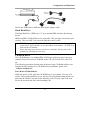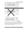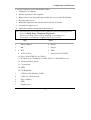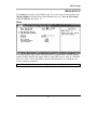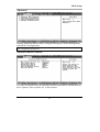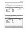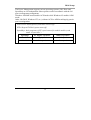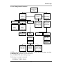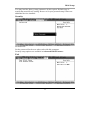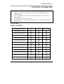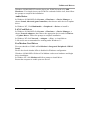
1
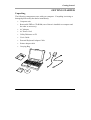
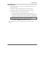
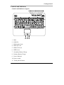
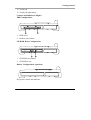
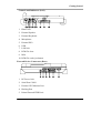
NOTEBOOK COMPUTER
RT-686 & RT-686EX
USER’S GUIDE
Copyright © 2001
All rights reserved. No part of this publication may be reproduced, transmitted,
transcribed, stored in a retrieval system, or translated into any language, or
computer language, in any form, or by any means, electronic, mechanical,
magnetic, optical, chemical, or other, without the prior written permission of the
manufacturer.
The manufacture reserves the right to revise this publication and to make changes
from time to time in the contents hereof without obligation to notify any person of
such revision or changes.
The manufacturer makes no representations or warranties, either expressed or
implied, with respect to the contents hereof and specifically disclaims any
warranties as to merchantability or fitness for any particular purpose. Any of the
manufacturer's software described in this manual is sold or licensed "as is".
Should the programs prove defective following their purchase, the buyer (and not
the manufacturer, its distributor, or its dealer), assumes the entire cost of all
necessary servicing, repair and any incidental or consequential damages resulting
from any defect in the software.
Trademark Acknowledgments
IBM, PC, AT, XT are registered trademarks of International Business Machines
Corp.
MS-DOS and Windows are registered trademarks of Microsoft Corp.
Pentium is the registered trademark of Intel Corp.
All product and company names are trademarks or registered trademarks of their
respective holders.
Warranty
This warranty gives you specific legal rights. You may also have other right that
may vary from state to state or country to country.
One-Year Limited Warranty
The company warrants its computer hardware products against defects in materials
and workmanship for a period of one year from delivery of the products. During
the warranty period, the company reserves the right to either repair or replace
products that prove to be defective.
Warranty Exclusions:
The warranty on your computer shall not apply to defects resulting from:
1. Vibration, shock, drop, dust, rain, high/low temperature, fungus, etc.
environmental exposure.
2. Improper or inadequate maintenance by the customer.
3. Improper site preparation and maintenance.
4. Unauthorized modification, change hardware configuration or misuse.
5. Customer supplied software or interfacing.
6. Operation outside of the specified ratings.
To maintain the warranty, you must have your computer serviced by an authorized
repair depot in the country of original purchase. You must prepay all shipping
charges, duties and taxes for products returned to your dealer.
Warranty Limitations:
The warranty set forth above is exclusive and no other warranty, whether written
or oral, is expressed or implied. Specifically disclaims the implied warranties of
merchantability and fitness for a particular purpose.
Some states or countries do not allow limitations on how long an implied warranty
lasts, so the limitation or exclusion in the previous section may not apply to you.
Any implied warranty of merchantability or fitness is limited to the one-year
duration of this written warranty.
Extended Warranty:
Please consult your dealer for details.
EMC Notice
FCC
Warning!
This equipment generates, uses, and can radiate radio frequency energy and if not
installed and used in accordance with the instructions, may cause interference to
radio communications. This equipment has been tested and found to comply with
Class B digital devices, pursuant to Part 15 of the FCC rules that are designed to
provide reasonable protection against such interference when operated in a
commercial or residential environment.
Countermeasures if interference occurs
You are encouraged to do the following if interference occurs while you are
operating the computer:
1. Turn OFF the computer and unplug the AC adapter from the outlet to see if the
interference disappears.
2. Connect the AC adapter to the outlet in another room and check if the
interference still exists.
3. Use an outlet that is far away from the interfered appliance.
4. Re-orient your computer in respect to the interfered appliance to see if there is
improvement.
If all of these failed, please call your dealer for help.
CE
This equipment complies with the requirements set out in the Council Direction on
the Approximation of the laws of the Member States relating to Electromagnetic
Compatibility (89/336/EEC). For the evaluation regarding the electromagnetic
compatibility, the following standards were applied:
EMI: EN55022 (CISPR 22) class B (conduction and radiation)
EMS EN55024
Harmonics: EN61000-3-2
Flicker: EN61000-3-3
ESD: EN61000-4-2
RS: EN61000-4-3
EFT: EN61000-4-4
Surge: EN61000-4-5
CS: EN61000-4-6
Power-Frequency Magnetic Field: EN61000-4-8
Voltage Dips, Interruptions: EN61000-4-11
UL, TÜV
AC Adapter (TÜV includes EN60950 LVD)
Power Conservation
This computer consumes much less power than conventional computers.
However, you still can reduce power consumption by properly configuring the
Power Management Setups.
It is recommended that you enable the power saving functions even when you are
not running with the battery.
Power Management generally does not degrade the system performance while
saving power.
Please read the power saving features and the setting procedures described in this
manual before setting your computer.
Recycling
All materials of the computer are recyclable or environmentally friendly. No CFC
or related materials were used in the manufacturing process or inside the product.
Please recycle the packing materials, and at the end of the computer's life, all other
materials in accordance with the local regulations.
Please refer “Material and Recycling” for the contents of the materials.
CONTENTS
GETTING STARTED ............................................................................................. 1
UNPACKING ........................................................................................................................... 1
QUICK OPERATION ............................................................................................................. 2
CONTROLS AND INDICATORS ........................................................................................ 3
USEFUL INFORMATION ................................................................................ 7
LOCATION ............................................................................................................................... 7
RUGGEDNESS ........................................................................................................................ 7
OPERATING SYSTEMS ....................................................................................................... 8
AC ADAPTER ......................................................................................................................... 8
BATTERY ................................................................................................................................. 9
BOOT UP AND POST....................................................................................................... 10
SUSPEND/RESUME ............................................................................................................ 11
SHUTDOWN .......................................................................................................................... 11
RTC ......................................................................................................................................... 11
REPLACING MODULES.................................................................................................... 12
COMPONENTS AND FUNCTIONS .................................................... 13
KEYBOARD ........................................................................................................................... 13
FLOPPY DISK DRIVE ........................................................................................................ 14
PRINTER CABLE ................................................................................................................. 14
HARD DISK DRIVE ........................................................................................................... 15
CD-ROM DRIVE .............................................................................................................. 15
IRDA TRANSCEIVER ....................................................................................................... 16
PCMCIA CARDS .............................................................................................................. 16
DOCKUNDER (OPTIONAL) ............................................................................................ 16
OPTIONAL DEVICES ........................................................................................ 20
MEMORY CARD ................................................................................................................. 20
2ND BATTERY ....................................................................................................................... 20
FAX/MODEM CARD ......................................................................................................... 20
LAN CARD .......................................................................................................................... 20
DVD ROM DRIVE .......................................................................................................... 20
CD-RW DRIVE .................................................................................................................. 20
2ND HDD ................................................................................................................................ 20
TOUCH SCREEN .................................................................................................................. 20
PCMCIA COVER.............................................................................................................. 21
VEHICLE ADAPTER .......................................................................................................... 21
DUAL BATTERY CHARGER .......................................................................................... 21
DOCKUNDER ....................................................................................................................... 21
SPECIFICATIONS .................................................................................................. 22
CPU ......................................................................................................................................... 22
MEMORY ............................................................................................................................... 22
DISPLAY ................................................................................................................................. 22
KEYBOARD ........................................................................................................................... 23
FLOPPY DISK DRIVE ........................................................................................................ 23
HARD DISK DRIVE ........................................................................................................... 23
CD-ROM DRIVE .............................................................................................................. 23
TOUCH SCREEN .................................................................................................................. 23
I/O PORTS.............................................................................................................................. 24
AC ADAPTER ...................................................................................................................... 24
VEHICLE ADAPTER .......................................................................................................... 24
BATTERY ............................................................................................................................... 25
SYSTEM UNIT DIMENSIONS AND WEIGHT ........................................................... 25
MATERIALS AND RECYCLING..................................................................................... 25
ENVIRONMENTAL ............................................................................................................. 26
BIOS SETUP ................................................................................................................... 27
MAIN ....................................................................................................................................... 27
ADVANCED........................................................................................................................... 28
ADVANCED BIOS FEATURES ..................................................................................... 28
INTEGRATED PERIPHERALS ......................................................................................... 29
POWER MANAGEMENT .................................................................................................. 29
PNP/PCI CONFIGURATIONS ........................................................................................ 32
DEFAULTS ............................................................................................................................. 32
SECURITY .............................................................................................................................. 33
EXIT ......................................................................................................................................... 33
UTILITIES AND DRIVERS .......................................................................... 35
VGA UTILITY..................................................................................................................... 35
DISPLAY CAPABILITY ..................................................................................................... 35
MOUSE DRIVER ................................................................................................................. 36
TOUCH SCREEN DRIVER................................................................................................ 36
CD-ROM DRIVER ........................................................................................................... 36
PCMCIA DRIVER ............................................................................................................ 36
AUDIO DRIVER ................................................................................................................... 37
LAN CARD DRIVER ........................................................................................................ 37
FAX/MODEM CARD DRIVER ....................................................................................... 37
MAINTENANCE / SERVICE ...................................................................... 38
CLEANING ............................................................................................................................. 38
TROUBLESHOOTING ......................................................................................................... 38
RMA SERVICE ................................................................................................................... 38
Getting Started
GETTING STARTED
Unpacking
The following components come with your computer. If anything is missing or
damaged please notify the dealer immediately.
•
Computer unit
•
Removable FDD or CD-ROM (one of them is installed on computer and
the other as accessory)
•
AC Adapter
•
AC Power Cord
•
Utility Diskettes or CD
•
User's Guide
•
External Keyboard Adapter Cable
•
Printer adapter cable
•
Carrying Bag
1
Getting Started
Quick Operation
•
Turn loose the battery screw to remove the battery insulation sheet then
fix the battery again.
•
Attach the AC adapter to charge battery for at least 10 minutes.
•
Turn ON the computer by pressing the power switch momentarily.
•
Turn OFF the computer by either of the following:
1.
Press power switch for 4 seconds makes a “Hard” power off.
System shut down immediately without saving any data or parameters.
2.
Press power switch momentarily causes “Suspend”* or “Hibernate”*
dependent on operating system (OS) and power management settings.
*: Some operating systems may not support these functions.
3.
Click Start → Shut Down in Windows to turn OFF.
Driver or application software installation may be necessary for further
operation.
2
Getting Started
Controls and Indicators
Controls and Indicators (Upper)
1. IrDA
2. PCMCIA
3. KB Number Lock
4. KB Caps Lock
5. KB Scroll Lock
6. HDD in use
7. Secondary Battery Charge
8. Primary Battery Charge
9. Power indicator
10. Power switch
11. Touch pad left button
3
Getting Started
12. Touch pad
13. Touch pad right button
Controls and Indicators (Right)
FDD Configuration:
1. FDD in use
2. Diskette eject button
CD-ROM Drive Configuration:
1. CD-ROM eject button
2. CD-ROM in use
Battery Configuration: (optional)
No special control and indicator.
4
Getting Started
Controls and Indicators (Left)
1. Phone Jack
2. External Speaker
3. External Keyboard
4. Microphone
5. External PS/2
6. USB
7. LAN Jack
8. PCMCIA slots
9. IrDA
10. PCMCIA card eject button
External Device Connectors (Rear)
1. DC Power Jack
2. Serial Port COM1
3. External CRT Monitor Port
4. Docking Port
5. Printer/External FDD Port*
5
Getting Started
6. Serial Port COM2 (or COM3 by optional configuration)
*: The port is a dual function port and default as printer output. System will
detect which device is attached and switch to proper output automatically.
Hot swap is possible under most conditions. However, if not able to hot
swap, please re-boot computer with the new device attached.
6
Useful Information
USEFUL INFORMATION
Location
A clean and moisture-free environment is preferred. Make room for air circulation.
Avoid areas with:
• Sudden or extreme changes in temperature.
• Extreme heat.
• Strong electromagnetic fields (near television set, motor rotation area, etc.).
• Dust or high humidity.
However, if it is necessary to work in a hostile environment, please regularly
maintain your computer by cleaning dust, water, etc. to keep it under optimal
condition.
Ruggedness
The computer is designed with rugged features such as vibration, shock, dust, and
rain/water protection. However, there is NO WARRANTY for such features.
Please provide appropriate protection while operating in harsh environments.
The computer designed to withstand rainfall from top with mild wind blowing
only. Please keep the keyboard facing up, i.e., normal operating direction, to
maintain water resistance. NEVER immerse the computer into water or spray
water with the system up side down. It may cause permanent damage.
The D-sub connector caps on the rear of the computer are for dust and shock
protection. The connectors are sealed internally. Other I/O ports and devices on
the left or right must have caps tightly closed or cable inlets sealed while exposed
to water or dust.
There are optional gaskets for DB-9 and DB-25 connectors. You may install them
to improve rain/dust/moisture resistance on your commercial type cable. Insert
the packing into the male connector (with pins) and fasten the screws.
All connectors will corrupt if exposed to water or moisture. They corrupt
even faster if the power is ON. Please take proper water-resistant measures
for cable connections.
The DC jack and cable are sealed which may operate with water splashing while
attached. All rubber caps should be closed when there is no cable attached.
7
Useful Information
Operating Systems
The computer is compatible with most operating systems (OS). However, not all
functions are 100% compatible.
For example, ACPI, APM, Smart Battery, etc. are not available on DOS,
Windows NT, and other non-Microsoft OS. Consequently “Suspend”,
“Hibernation”, “Battery Gauge” etc. would not work under such operating
systems.
ACPI: Advanced Configurations and Power Interface
APM: Advanced Power Management
AC adapter
The AC adapter performs two functions:
• It powers the computer from an external AC source.
• It charges the computer battery.
The adapter automatically detects the AC line voltage (110V or 220V) and
adjusts accordingly.
The following are recommended when using the AC adapter:
• Use a properly grounded AC outlet.
• Use one AC outlet exclusively for the computer. Having other appliances
on the same line may cause interference.
• Use a power strip with built-in surge protection.
Connect the AC adapter:
1. Plug the AC cord to the adapter.
2. Plug the other end of the AC cord into the wall outlet. Make sure the green
LED on the adapter turns on.
3. Attach the DC plug into the power jack of the computer; turn the lock ring
clockwise to secure it.
AC Adapter Indicator
The green LED indicates that the AC power is ready.
8
Useful Information
Battery
The computer will automatically switch to the battery power when the AC
adapter is disconnected.
Battery Power Saving Tips
The computer comes with an intelligent power-saving feature. You may extend
the battery life by:
•
Setup power saving functions in BIOS Power Management Setup.
•
Setup power saving functions in Operating System Power Management
options (e.g. Windows 98/2000/ME Power Management Options).
•
Lower the intensity of the display by brightness control.
•
Suspend the computer when temporarily leave the work.
•
Shut down the computer when leave the work for a longer time.
Battery Low
When the battery is nearly exhausted, the computer gives the following “Battery
Low” warnings:
•
Windows 98/2000/ME battery low warning (when operating system is
Windows)
•
A series of beeps per minute.
•
The power LED flashes.
Once the Battery Low warning occurs, please:
1. Save and close the files you are currently working on.
2. Plug in the AC adapter to recharge the battery.
Battery Gauge
In Windows 98/2000/ME, etc. you may get battery status information from
battery gauge. Click the power/battery icon then the battery gauge screen pops
out.
9
Useful Information
Note: Battery characteristic varies depending on factors such as ambient
temperature, charging method, load current, aging, etc.
For example, at low temperature the chemicals of the battery are more
inactive, thus decreases the output power.
The battery gauge can only be taken as a reference. Please do not expect
it to show the exact amount of the power remaining.
There is no memory effect on Lithium Ion battery cells. However,
discharge the battery to nearly empty every 2~3 months would help the
internal gauge to reset its readings.
Charging the Battery
Plug in AC adapter starts the battery charge. If the battery is already full, the
sense circuitry will stop high current charge within several minutes.
There are two LED indicators next to power indicator for Primary and Secondary
battery respectively. Indicator turns ON when the battery is charging. They will
turn OFF when the battery charge is completed.
To charge the Secondary Battery, simply install it into the computer and attach
the AC adapter. The internal charger will charge the Primary and Secondary
batteries at the same time.
Optional Dual Battery Charger can charge Primary and Secondary batteries
externally.
Boot Up and POST
The computer turns ON and loads the operating system (such as Windows) into
the system memory. This start-up procedure is called “boot up”.
10
Useful Information
The ROM BIOS Power On Self Test (POST)
Each time the computer powers on, it automatically performs a self-test of its
memory and hardware devices.
Suspend/Resume
The system can enter suspend mode by either pressing the power switch or
staying idle till Suspend Timeout. Windows “Suspend”, ”Standby” can also
activate the function.
Please refer “BIOS Setup Power Management“ for details.
Note: Suspend/Resume works under both AC adapter and battery mode.
“Hibernate” may not work under Windows NT or other non-Windows
operating systems.
Shutdown
The following procedure is recommended in shutting down the computer:
1. Save any work you want to keep into the disk.
2. Make sure none of the disk drives are active (HDD, FDD, and CD-ROM
drive).
3. Remove any diskette from the FDD.
4. Proceed the shut down procedure of your Operating System
5. Let the computer shut down or push the Power Switch to turn OFF.
Failure to shut down the computer properly may result in loss of data or hardware
damages.
Automatic shut down is activated at battery exhaust. Be sure to finish your work
and save all your data when the battery low warning appears.
RTC
Battery backed up RTC (Real Time Clock/Calendar) is built in an on-board
CMOS (Complementary Metal Oxide Semiconductor) chip. The RTC keeps
track of the time and date while the computer is off. The CMOS chip also stores
system setup information.
RTC battery is also recharged when AC adapter is attached. Recharge the
computer approximately once per month to ensure RTC operation.
11
Useful Information
Replacing Modules
Caution! You must turn the power OFF before replacing the FDD, CD-ROM,
and HDD modules.
To remove the modules:
1. Turn OFF the computer or hibernate (suspend to disk).
2. Disconnect all cables from the computer.
3. Use a coin to turn loose the screws on the modules.
4. Remove the battery from the compartment.
5. Push the latch knob to release the CD-ROM or HDD module and push them
outward.
6. Remove the module from the computer.
To re-install the modules:
Gently push the module into the slot. Fasten the screw to fix the module.
12
Components and Functions
COMPONENTS AND FUNCTIONS
Keyboard
The keyboard is functionally equivalent to a full size desktop keyboard.
A sample key layout is shown below.
The Numeric Keypad
The numeric keypad functions like an electronic calculator. It is embedded in the
main keyboard, with the numeric figures printed on the upper right of their
respective keys. The keypad has keys for the digits 0 through 9, the decimal point
( . ), addition ( + ), subtraction ( - ), multiplication ( * ), and division ( / ).
To activate the keypad, press the Num Lock key. The 15 keys shown in the figure
switch from alphabetic keys to numeric keys. Press Num Lock again switches the
keys back to alphabetic.
13
Components and Functions
Keyboard Backlight (optional)
Press [Fn] [F5] key for approximately 1 second turns keyboard backlight ON or
OFF.
Floppy Disk Drive
The computer comes with a 3.5" 1.44MB floppy disk drive (FDD). The 1.44MB
FDD can also read and write 720KB double side double density diskette. It is
recommended that high density (2HD marking) diskette been used only.
FDD can be removed and swapped with CD-ROM drive or 2nd battery. When
CD-ROM drive or 2nd battery is installed, you may still use FDD by connecting it
via the rear DB-25 port.
LS-120 Drive (optional)
LS-120 drive plugs to the same connector of FDD/CD-ROM drive. It cannot
attach to the rear Printer/FDD connector. LS-120 interface is via IDE so there is
no connector for external connection. It must be installed in the FDD/CDROM/2nd Battery compartment only.
No device driver needed under Window 98/2000/ME. Driver loading is necessary
when working under non-Windows OS.
To boot up from LS-120 drive you should set boot sequence as “LS-120, C” in
“Advanced BIOS Feature”.
For first time use, the computer will recognize LS-120 as a conventional 1.44MB
FDD and boot up normally. Then you may install Windows or load driver for
DOS depending on your needs.
The diskette for LS120 is either 1.44MB or Super Disk 120MB.
Diskette eject is controlled by electric motor mechanism. Insert/Remove diskette
when the power is ON.
Printer Cable
For most printers there is no special requirement in connection. However, some
printer cable does not contain all 25 wires. To avoid malfunction, the printer
adapter cable comes with your computer should be attached to the printer cable.
The purpose is to re-connect all the ground pins. Devices equivalent to printer
such as scanner, Laplink cable, etc. also need this cable.
14
Components and Functions
Please note FDD cable is different from printer adapter cable.
Hard Disk Drive
The Hard Disk Drive (HDD) is a 2.5” type standard IDE interface data storage
device.
HDD and FDD, CD-ROM drives are removable. This provides convenience and
security. They can ONLY be removed while the power is OFF.
Note: NEVER drop your HDD, FDD, CD-ROM module or expose them to high
temperature, high humidity, or any hazardous environment. NEVER try to
disassemble the module.
Static discharge may destroy your device and data. Always pick up the
modules by touching the case only.
CD-ROM Drive
The CD-ROM drive is a standard IDE ATAPI type, which accepts a variety of
standard 12cm CDs such as CD-ROM, audio CD, CD-I, Photo CD, video CD,
etc.
The following procedure assumes that all the necessary CD-ROM utilities were
installed on the computer. For CD-ROM utility installation, please refer
“Utilities and Drivers”.
Put CD into CD-ROM drive
While the power is ON, push the CD-ROM drive's eject button. The tray will
release. Then gently pull the tray out. Put the CD on the holder and push the tray
back into the cabinet. Any dirt on the data side of the CD may cause read error.
Please do not touch this side when handling CDs.
15
Components and Functions
Read from CD-ROM drive
The CD-ROM drive may be designated as drive D: or higher depending on your
configuration. You may access it in DOS or Windows the same way you would
for the floppy disk drive or hard disk drive. The CD-ROM is a read-only device.
Any command attempting to write onto it will be denied.
Please avoid shock or vibration while the CD-ROM drive is active.
IrDA Transceiver
You may transfer or receive data to and from another computer via infrared ray if
that computer is also equipped with an IrDA transceiver. Please make sure the
linking utility is IrDA compliant.
Define the port and controller type before running linking utility. The port is
“COM2” and the I/O controller is SMC37C869LV.
Set COM2 port as “IR” in Integrated Peripherals of BIOS Setup to enable it.
IrDA: Infrared Data Association
PCMCIA Cards
The computer supports two type-II PCMCIA cards or one type-III card. To
remove the card, push the button on the right of the card to eject it. The eject
button can hide into the compartment by pushing it inward gently.
DockUnder (optional)
DockUnder is the device for system unit docking. The AC adapter or vehicle
adapter can attach to DockUnder and automatically charge the computer while
docked.
Mount the DockUnder:
1. Turn OFF the power.
2. Open the rubber cap of the docking connector.
3. Align the docking connector.
4. Push the computer to join the guiding pins. Do not lift the computer up while
docking.
16
Components and Functions
Note: Do not lift up the computer while engaging.
5. Lock the computer.
There is 1 PCI slot on the DockUnder-Office. Maximum card dimensions is
260mm (L: length, including L-bracket thickness) x 115mm (W: width, including
gold fingers) x 24 mm (H: height, including PCB 1.6mm, components side
17mm, solder side 5mm). The maximum power rating of PCI card is +5V 1A,
+3.3V 1A, +12V 100mA, -12V 100mA.
17
Components and Functions
To install expansion card in DockUnder-Office:
1. Unplug the AC adapter.
2. Release and remove the computer.
3. Remove the screws fixing the upper and lower covers of the DockUnder.
1. Open the upper cover.
2. Install the expansion card into the slot and fix the L-bracket.
3. Assemble the upper cover.
4. Attach the computer and perform functions test.
Note: You may have to free IRQ for your expansion card by disabling unused
device in BIOS Setup “Integrated Peripherals”.
Please check IRQ conflict before installing cards and drivers.
Never dock or un-dock the computer while power is ON.
IRQ
DMA
0
Timer output 0
0
1
KB
1 Sound
RTC
2
2
8
9 ACPI (or Free)
Sound
FDD
3 Reserved (or ECP/EPP)
10 Free (16-bit PCMCIA, or COM3*)
11 PCI devices or Card Bus 0/1 (Sound, LAN*, 32-bit PCMCIA, etc.)
12 Touch pad (PS/2 mouse)
13 Co-processor
14 HDD
15 CD-ROM drive
3
COM2 (or Fax/Modem*, IrDA)
4
COM1 (or Touch screen)
5
Free (COM4*)
6
FDD
7
Parallel port 1
18
Components and Functions
*: Optional devices.
19
Optional Devices
OPTIONAL DEVICES
Memory Card
The memory card will expand your memory to facilitate better system
performance. The cards are available as following:
32MB, 64MB, 128MB
2nd Battery
A Lithium Ion rechargeable 2nd battery may install into the CD-ROM/FDD
compartment. It has the same capacity of primary battery and Smart Battery
compliance.
The computer’s internal charger can detect 2nd battery and perform charging
accordingly.
Fax/Modem Card
V.90 56K Fax/Modem card.
LAN Card
100 Base-T Ethernet LAN card for a wired network.
DVD ROM Drive
Swappable with CD-ROM drive for DVD playback. Backward compatible with
CD-ROM, VCD, etc.
CD-RW Drive
Swappable with CD-ROM drive for writing CD-R. Backward compatible with
CD-ROM, VCD, etc.
2nd HDD
Swappable with CD-ROM drive. Set as IDE secondary master drive.
Touch Screen
Capacitive or resistive touch screen facilitates direct finger touch or pen input
instead of mouse or touch pad.
20
Optional Devices
Capacitive touch screen needs a ground loop between human body and screen
panel’s ground terminal. Otherwise it would not activate when touched with one
hand. It is generally OK if the AC adapter is attached or the computer/panel is
mounted on a vehicle’s metal parts. Holding the computer/panel with the other
hand will form the loop, too.
PCMCIA Cover
Besides the attached PCMCIA rubber cover, there is an optional cover with a
metal frame that can be fixed by screws. The cover provides protection from dust
or water for cabled PCMCIA cards. Users may glue the cable outlet to seal it.
Vehicle Adapter
Converts power from car lighters or truck batteries to DC +19V, the same output
ratings as AC adapters. It can power the system and charge the batteries
simultaneously.
Remove or disconnect the adapter when leaving the vehicle to avoid battery
exhaustion.
Dual Battery Charger
This charger provides two slots for the Primary and Secondary battery
respectively. It allows charging of both batteries simultaneously. Accepts power
from AC adapter or Vehicle adapter. It takes approximately 3 hours to fully
charge both batteries.
DockUnder
There are 2 DockUnder models available. One for office installation and one for
vehicle installation:
DockUnder-Office accepts 1 PCI card and duplicates COM1, COM2, Parallel,
2 USB, and PS/2 port. Ports are on the rear.
DockUnder-Vehicle duplicates COM1, COM2, Parallel, 2 USB, and PS/2 port.
Ports are on the bottom.
21
Specifications
SPECIFICATIONS
CPU
Intel Mobile Pentium III
CPU runs at 2 speeds: High speed (AC adapter mode), Low speed (Battery mode)
The CPU speed switches automatically.
Memory
System memory
Minimum: 64MB
Expandable: 128MB, 192MB, 256MB, 384MB,
512MB
Cache memory
Internal level-1 32KB, level-2 256 KB
Video memory
8MB
Display
The display is a SVGA compatible LCD (Liquid Crystal Display) of 800 x 600
dots (horizontal x vertical) or 1024 x 768 dots with 16M true color. The
computer is also capable of displaying Super XGA 1280 x 1024 dots full screen
on external CRT monitor (Cathode Ray Tube).
LCD applies a “Panning” technique to display resolutions higher than 800 x 600
or 1024 x 768 dots. In Panning, you may move the cursor out of the screen
boundary, then the display will scroll to show the hidden area.
LCD:
Type:
12.1” Active TFT Color
13.3” Active TFT Color
Resolution:
800 x 600 pixels (12.1”)
1024 x 768 pixels (13.3”)
Mode:
VGA, EGA, MGA, SVGA, and XGA
Color:
16.8 million true colors on 800 x 600 and 1024 x 768
mode
Characters x Row:
80 x 25
22
Specifications
Keyboard
Number of keys:
89
Key travel:
2.5 mm (standard)
1.5 mm (optional backlight)
Function:
Emulates standard 101/102-key keyboard
Floppy Disk Drive
Standard:
Size:
3.5"
Capacity:
1.44MB (formatted)
Rotation:
300 RPM
Transfer Rate:
500KB/sec
Average Access:
94 ms (with settling)
Hard Disk Drive
Type:
Interface:
2.5”
IDE Ultra DMA 33 compliant
CD-ROM Drive
Speed:
Interface:
24 x
(ATAPI)
Data transfer rate:
16.7MB/sec
Modes:
CD-ROM mode 1 & 2, CD-Audio, VCD, Multisession Photo CD
Dimensions:
128mm (W) x 130mm (D) x 12.7mm (H)
Weight:
280g
Touch screen
Type:
Capacitive or Resistive
Interface:
Serial
Resolution:
>1024x1024
23
Specifications
I/O ports
•
Parallel port
•
Two Serial ports
•
External CRT monitor port
•
External Keyboard port
•
External PS/2 port
•
Audio ports (External Speaker, Microphone)
•
RJ11 Phone jack for internal Fax/Modem (optional)
•
RJ45 jack for internal LAN card (optional)
•
2 type II or 1 type-III PCMCIA slots
•
Printer/External FDD port
•
Docking port
•
USB port (Universal Serial Bus)
AC Adapter
Voltage:
AC 90 - 240 V
Frequency:
50/60 Hz
Output Voltage:
DC 19V
Maximum Power:
60 Watts
Dimension:
122 mm(W) x 55mm(D) x 29mm(H)
Weight:
240 g (0.52 lb.)
Vehicle Adapter
Input Voltage
12V/24V (10~32V) Auto-sense
Input Current
2.5A/5.5A max. (12V/24V respectively)
Output Voltage
19V +/-5%
Output Current
2.8A
Wiring
Cigarette lighter/ Truck battery
24
Specifications
Application
Car or Truck installation
Battery
Primary Battery:
Type:
9 x 18650 cells Lithium Ion
Capacity:
Dimension:
10.8V 5400mAH
103 mm(W) x 73 mm(D) x 38 mm(H)
Weight:
435 g (0.95 1b.)
2nd Battery (optional):
Type:
9 x 18650 cells Lithium Ion
Capacity:
10.8V 5400mAH
Dimension:
150 mm(W) x 90 mm(D) x 20 mm(H)
Weight:
560 g (1.2 1b.)
System Unit Dimensions and Weight
Width:
Depth:
312mm (12.3”)
246mm (9.7”)
Height:
62.5mm (2.5” )
Weight :
4.7Kg (10.3 lb., including FDD and primary battery)
Note: Weight varies depending on system configurations.
Materials and Recycling
Materials of the computer are as follows:
Cabinet:
Aluminum alloy ADC-12 or A380,
Magnesium alloy AZ91D,
UL grade PC+ABS GE C6200 or TN-3813BW
Bracket:
Aluminum 5052, Steel with Nickel plating, or Stainless Steel
S304
PCB:
FR-4, UL 94V0
Battery:
Rechargeable Lithium Ion, 9 cells per pack
25
Specifications
Packing: Carton: Unbleached paper
Cushion: Recyclable PE
Carrying bag: Recyclable PE Fiber
User's Guide: Paper
Please recycle the parts according to local regulations.
Environmental
Temperature:
0 ~ 45ºC (32 ~ 113ºF) operating
-20 ~ 60ºC (-4 ~ 140ºF) storage
Humidity:
5~95% Non-condensing operating
95% maximum storage
Altitude:
0 ~ 4570 meters (0 ~ 40,000 feet) operating
26
BIOS Setup
BIOS SETUP
Press [Del] at boot up to enter BIOS setup. Use arrow keys to select options and
[PgUp] [PgDn] to modify them. When finished, move to ”Save & Exit Setup”
and press [Enter] then press “Y”.
Main
You may set time, date, HDD, FDD parameters in Main Setup. Set IDE Primary
Master (HDD) and IDE Secondary Master (other IDE devices, such as CD-ROM
drive) as “Auto”. Since the HDD is detected automatically, you usually do not
need to setup its parameters.
Note: The contents may vary depending on computer configuration.
27
BIOS Setup
Advanced
Includes Advanced BIOS Features, Integrated Peripherals, Power Management,
and PnP/PCI Configurations.
PnP: Plug and Play devices.
Advanced BIOS Features
You may set a quicker boot up (minimized self test procedure) or define boot up
drive sequence, boot up status, etc. in this window.
28
BIOS Setup
Security option:
“Setup”: Password prompt at BIOS Setup. Only authorized user may perform
setup.
“System”: Password prompt at boot up. Only authorized user may boot up the
computer.
Integrated Peripherals
Serial, Parallel, and other ports’ modes are defined by this setup. You may
disable some devices to free IRQ when necessary.
Power Management
29
BIOS Setup
The Power Management supports various operating systems (OS). Doze and
SpeedStep are OS-independent. Other options work in accordance with the OS
power management components.
Windows 2000/ME would enable ACPI mode while Windows 95 enables APM
mode.
Other OS (DOS, Windows NT, etc.) without ACPI or APM would apply generic
power management.
POS: Power On Suspend (system does not turn off)
STD: Suspend To Disk (system turns off)
SpeedStep: Intel proprietary CPU speed control for mobile models (code
name “Geyserville”)
SpeedStep
AC adapter operation
Battery operation
Enabled
High speed
Low speed
Disabled
Low speed
Low speed
30
BIOS Setup
Power Management Functions:
BIOS Power
Management
Setup
Power
Management
(DOS,
Windows NT,
or others)
Max Saving
Min Saving
Fixed shortest
timeout for
Doze,
Standby,
Suspend, HDD
Fixed longest
timeout for
Doze,
Standby,
Suspend, HDD
HDD Power
down
POS
(CPU halt, PCI
clock stop,
LCD OFF)
SpeedStep
Support
User Define
Doze
(CPU halt)
When disabled
CPU always
run at battery
mode speed
(low speed)
HDD Power
down
ACPI/APM
(Windows 98,
2000, ME, or
other OS with
ACPI/APM)
Windows (OS)
takes control
of power
management
Doze
(CPU halt)
Standby
(CPU halt,
LCD OFF)
Standby
(CPU halt,
LCD OFF)
Suspend
Suspend,
Hibernate
STD
(Suspend to
disk then
shutdown
system)
Auto
(Automatically
switch from
POS to STD
after timeout)
If STD is set, you should allocate a disk space to store the memory data. A utility
ZVHDD.EXE performs FAT file allocation.
Run ZVHDD.EXE under DOS prompt.
Following is a sample command:
ZVHDD /C /FILE /M:136
31
BIOS Setup
The system will create a partition on the HDD to store memory data with file size
of 136MB. You must specify a file size larger than your system memory plus
video memory (8MB). For instance, if system memory is 128MB you should at
least set 136MB.
Type ZVHDD /? for more information.
PnP/PCI Configurations
You only need to set this option when using a non-Windows OS.
Defaults
Load Fail-Safe Defaults:
32
BIOS Setup
You may load the factory setup parameters by this option. Default setup is
usually the most fail-safe setting. Be sure to set your personal setup if there are
additional devices installed.
Security
Set Password:
Set the password for the user who works with this computer.
Security setup options are available in Advanced BIOS Features.
Exit
33
BIOS Setup
Choose “Save & Exit Setup” when you are sure of the setup. Choose “Exit
Without Saving” when setup change is not needed.
34
Utilities and Drivers
UTILITIES AND DRIVERS
Note: Most device drivers are available in Windows 98/2000/ME. Only when the
default driver does not work properly you need to install the factory
bundled drivers.
Driver installation is necessary for DOS, Windows NT, or other nonMicrosoft OS.
The utility CD includes most drivers.
Re-install drivers or perform “Driver Update” to replace the Windows
default drivers.
VGA Utility
Display Capability
Resolution & Color
LCD
CRT
LCD + CRT
640x 480x 256 color
640x 480x 64K color
640x 480x 16M color
800x 600x 256 color
800x 600x 64K color
800x 600x 16M color
1024x 768x 256 color
1024x 768x 64K color
1024x 768x 16M color
1280x 1024x 256 color
*
*
1280x 1024x 64K color
*
*
1280x 1024x 16M color
*
*
35
Utilities and Drivers
1600x 1200x 256 color
*
*
1600x 1200x 64K color
*
*
*:
By Panning.
The table lists typical display modes only. The system also supports standard
video modes with lower resolution and color.
Windows 98/2000/ME/NT Driver Installation:
Insert the Driver CD into the CD-ROM. Click Display in Control Panel then
select Settings, follow prompt to complete driver installation. Windows
98/2000/ME may recommend using their driver, but you should confirm changing
to the factory bundled driver.
Back to Settings window, choose proper Colors and Screen Area, then click OK
and restart Windows.
Mouse Driver
The mouse driver is not included in utilities It is usually not necessary to install a
mouse driver because the operating system will do it automatically.
You may obtain mouse driver from the dealer if it’s really needed.
Touch Screen Driver
First please enter BIOS Setup and set COM1 port as “Touch Screen”. (Optional
COM4 may be configured as touch screen, too.)
Then install the drivers under Windows by Add Hardware.
CD-ROM Driver
In Windows 98/2000/ME/NT, you don’t need to install drivers, because it is
included in the drivers list.
Only DOS needs the driver
PCMCIA Driver
Windows 98/2000/ME/NT
The driver is automatically installed under Windows.
36
Utilities and Drivers
Windows 98/2000/ME/NT can also detect new PCMCIA cards or by Add
Hardware. You simply insert your PCMCIA card and click the icon, then follow
the prompt to complete the installation.
Audio Driver
In Windows 98/2000/ME click System → Hardware → Device Manager →
choose Sound, video and game controllers, then choose audio device to update
driver.
In Windows NT, Click Multimedia → Peripheral → Driver to install it.
LAN Card Driver
In Windows 98/2000/ME click System → Hardware → Device Manager →
choose Network adapters, then choose the appropriate device and click Driver
→ Update Driver. Follow the prompt to complete installation.
In Windows NT click Network → Adapter → New .. to install driver.
LAN card is not recommended for working under Windows 3.1.
Fax/Modem Card Driver
First you should set COM2 as Fax/Modem in Integrated Peripheral of BIOS
Setup.
Please also check whether IrDA is disabled in Windows configuration.
Windows 98/2000/ME will detect Fax/Modem card as new hardware and begin
driver installation.
In Window NT click Modem and follow prompt to install driver.
Restart the computer to enable your new device.
37
Maintenance/Service
MAINTENANCE / SERVICE
Cleaning
Wipe the exterior with a clean, soft, and lint-free cloth. If there is difficulty to
remove dirt, apply non-ammonia, non-alcohol based glass cleaner onto the cloth.
An air gun is recommended for cleaning water and dust. For salty water
please clean with fresh water then blow-dry with an air gun. Be sure not to
turn the computer up side down while there is water being applied.
ALWAYS turn OFF the power, unplug the power cord and remove the
battery before cleaning.
Troubleshooting
Should the computer failed to function properly, you may try the following to
troubleshoot it.
•
Check AC/vehicle adapter, battery, and the power source.
•
Minimize the configuration, i.e., remove extra peripherals and devices.
•
Remove the modules one by one (HDD, CD-ROM, FDD, Battery, etc.).
•
Remove the software suspected.
•
Set BIOS fail-safe default.
•
Re-install operating system and application software.
RMA Service
If all of the user troubleshooting approaches still cannot help, consult the dealer
for service. When sending out the computer, please follow the re-packing guides:
•
Remove the CD/diskette (if any) in the CD-ROM/floppy disk drive.
•
Use the original shipping container and packing materials if possible.
•
When not using the original packing material, wrap the equipment with
soft material (e.g., PU/ PE form) then put it into a hard carton.
•
Secure the separate parts so they would not mix together during
transportation.
38
Maintenance/Service
•
Send ALL parts of your configuration, including hardware/software, if
possible.
•
Include DETAILED descriptions of the problems you encountered, and
the list of your hardware/software configuration.
39
Recycled / Recycleable
Printed in Taiwan